

Integrated Visual Data Technology Inc. SkidWeigh ED2E-EP Series, SkidWeigh DL2E-EP Series Installation & Calibration Manual
Page 1
Installation & Calibration Manual
Electric Pallet Truck Check Weighing Systems
SkidWeigh Series ED2E-EP and DL2E-EP
ED2E-EP V1500
Integrated Visual Data Technology Inc. 3439 Whilabout Terrace, Oakville, Ontario, Canada L6L 0A7
www.skidweigh.com
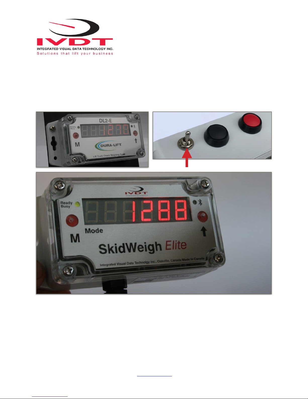
Power On / Off Switch
Page 2

General Installation Guide
This SkidWeigh Series ED2E-EP / DL2E-EP system installation & calibration guide describes how to install, calibrate,
test and use your electric pallet truck on-board weighing system. Following the instructions in this guide will enable you
to get your system setup and operating quickly. In the event that you require additional assistance, please contact
customer support via e-mail at support@skidweigh.com, visit www.skidweigh.com or contact us at the address and or
contact number below:
Integrated Visual Data Technology Inc.
3439 Whilabout Terrace, Oakville, ON, Canada, L6L 0A7
Phone: 905-469-0985
Safety
Always disconnect the vehicle battery while installing SkidWeigh systems or any other electronic product.
Make sure that unit, pressure transducer and any other associated cables are securely mounted and do not impede any
of the vehicle’s controls. Use care when routing the component cables. Route the cables where they will be protected.
Use commonly accepted install practices for after market industrial vehicle electronic devices.
The installation of the SkidWeigh systems should only be performed by a knowledgable lift truck dealer technician or end
user with electro and hydraulic experience.
Here are two acceptable methods of making a wire connections:
* Soldering your connections (recommended)
* Crimp connectors ( with the use of the proper crimping tool)
Regardless of the method you choose, ensure that the connection is mechanically sound and properly insulated. Use
high quality electrical tape and shrink tubing where necessary. This product is connected directly to the vehicle’s ignition
switch, operating voltage from 12 to 55 VDC.
Electro-Magnetic Compatibility
CE conformity to EC directive 89/336 (EMC) by application of harmonized standards: Interference stability EN 61000-6-2
and EN 61326-1 interference emit EN 61000-6-3, EN 61326-1 for the pressure transducer.
SkidWeigh ED2E-EP / DL2E-EP Series
Our policy is one of continuous improvement and the information in this document is subject to change without notice.
Check that software version displayed on LED is the one applicable for your application.
Overview of Components
The standard SkidWeigh ED2E-EP / DL2-EP Series check weighing system consist of the following components:
* Digital indicator with wiring harness, mounting bracket and anti-vibration mount
* Hydraulic pressure transducer with 3 wires cable
* Installation & Calibration manual and operator usage instruction
Integrated Visual Data Technology Inc. 3439 Whilabout Terrace, Oakville, Ontario, Canada L6L 0A7
www.skidweigh.com
Page 3
Operational Principal
The SkidWeigh ED2E-EP / DL2E-EP system operation principal is
based on the hydraulic pressure transducer mounted in the vehicle
lifting hydraulic circuit. The increase in the hydraulic pressure will
activate the specific “weighing cycle” algorithm and initiate automatic
motion control of the hydraulic lift motor. The microprocessor will take a
readout of the predetermined valid pressure transducer input at a
sample rate of 16000 readings per measurement session and will
convert it to the load weight that will be shown on LED display.
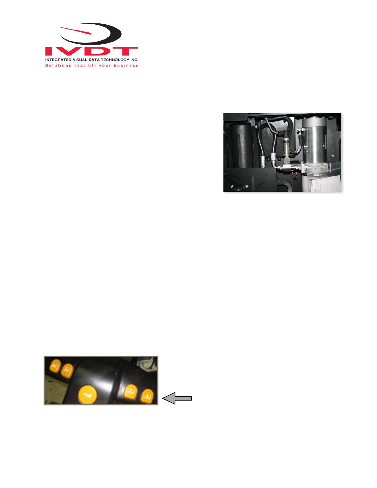
Pressure Transducer Installation
The pressure transducer must be installed in the lifting hydraulic line between the lift control valve and lift cylinder.
Mount a T-piece in hydraulic line for the installation of the pressure transducer.
2 Methods for Automatic Pump Motor De-Activation During Load
Weighing Cycle
Two BLACK wires are connected to the internal relay located in the ED2E-EP / DL2E-EP digital indicator. The inter-
nal relay is controlled by the microprocessor and activated only during the load weighing cycle. There is no power
connected to these two BLACK wires ! Internal relay configuration is SPDT.
Method A. (Preferred Method)!
Use the two BLACK wires to “splice” them in series with the operator activated lift control switch wire or signal
wire from the electronic controller that is activating the lift pump motor solenoid.
Note: The predetermined motion of the lifting cylinder and the load weight measurement “weighing cycle” will be
initiated and controlled automatically by the software algorithm based on the input signal from the pressure transducer. Once the load weight is shown on the LED display the internal relay will be de-activated and the lift pump
motion control will be back to normal operation . (With the vehicle at a stationary position during the lifting cycle
diagnostic display on some vehicles may show ‘No power to lift motor’ or audio signal might be activated for
short time period.)!
Consult Vehicle Wiring Diagram !
Integrated Visual Data Technology Inc. 3439 Whilabout Terrace, Oakville, Ontario, Canada L6L 0A7
www.skidweigh.com
Operator Activated
Lift Pump Motor Control Switch
Page 4

Method B.!
Use the two black wires and splice them in series with one of the lift pump solenoid coil wires activating the
pump motor.
Disconnect one of the original solenoid coil wire ( From either positive or negative terminal of the solenoid coil )
and splice the two bLACK wires in series to the disconnected wire and solenoid terminal.!
Note: The predetermined motion of the lifting cylinder and the load weight measurement “weighing cycle” will be initiated
and controlled automatically by the specific software algorithm based on the input from the pressure transducer signal.
(With the vehicle at a stationary position during the lifting cycle diagnostic display on some vehicles may
show ‘No power to lift motor’ or audio signal might be activated for short time period.) Unloaded vehicle is
motion may produce hydraulic spikes that are detected by the pressure transducer sending a signal this may
be seen by the vehicle controller as starting the “weighing cycle”. Short interruption of the power to the lift
solenoid coil on some controllers are seen as a fault and power to the vehicle will be cut.
SkidWeigh ED2E-EP / DL2-EP Power Off
When weighing function is not required and to avoid interruptions due to
lift cut outs simple turn the system off !
Pressure Transducer Installation Precautions
Before installation of the pressure transducer the hydraulic lift circuit must be
pressure free.
Make sure that the installed pressure transducer will not touch any moving parts or
vehicle assembly once installed while in normal operation. The pressure
transducer has a 1/4”-18 NPT male thread. Use thread seal to ensure tight fit.
Integrated Visual Data Technology Inc. 3439 Whilabout Terrace, Oakville, Ontario, Canada L6L 0A7
www.skidweigh.com
Power On / Off Switch
Page 5

Selecting the Mounting Location for Digital Indicator
Use the mounting bracket with the anti vibration mounts and fasten the digital indicator to the vehicle dashboard, or any
other convenient place on the electric pallet truck body There are many examples of mounting locations that will depend
on the vehicle model. However, additional mounting items such as a flat brackets may be needed to help secure the unit.
Electrical Connections!
All SkidWeigh systems operate from 12 to 55 VDC.
Orange Wire (+) Key switch On position
Brown Wire (-) Battery negative
Red Wire, connect to RED wire of the pressure transducer cable
Black Wire, connect to BLACK wire of the pressure transducer cable
White Wire, connect to WHITE wire of the pressure transducer cable
Two black wires are connected to the internal relay located in the ED2E-EP / DL2-EP digital indicator. The internal
relay is controlled by the microprocessor and activate only during the load weighing cycle. There is no power con-
nected to these two black wires. !
Electrical Power Short Circuit Protection
- All SkidWeigh systems are internally short circuit protected with a resettable fuse. There is no need to install external
inline fuse in the orange wire connected to the ignition switch.
- Automotive 60 V load dump protection
- Reversal power supply protection
Weighing Function Calibration Procedure
The SkidWeigh ED2E-EP / DL2-EP calibration is automatic and is done by lifting empty and loaded forks to
initiate and program the automatic weighing cycle. MAKE SURE THAT YOU HAVE A KNOWN LOAD WEIGHT
AND KEEP IT NEARBY TO COMPLETE THE SYSTEMS CALIBRATION PROCESS.
For the best results use at least minimum calibration load test weight of 50% to 80% of maximum lifting capacity of the
electric pallet truck. Use floor scale or find a known load weight with a confirmed and trusted weight.
Important:
If you want the system to show load weight in pounds, use the known load weight in pounds and enter that
value accordingly. The same would apply if you want the system to show load weight in kilograms. Use the
known load weight in kilograms and enter that value into the system accordingly.
Integrated Visual Data Technology Inc. 3439 Whilabout Terrace, Oakville, Ontario, Canada L6L 0A7
www.skidweigh.com
Page 6

Starting the Calibration Procedure
Lower the Empty Forks to the Ground
There should be no hydraulic pressure in hydraulic lift circuit.
- Turn power switch to on position
- If the LED display does not show any number(s), turn on the main power switch
located on top of the housing.
- LED display will show software version on the right side and number 8 will be
shown in Mode window.
Calibration with Empty Forks
With lowered empty forks on the ground and Mode 8 showing
To initiate calibration procedure, press the ‘M’ button using a paper clip
Hold the ‘M’ button down for approximate 5 seconds. !
!
After 5 seconds the Mode 8 digit will change to Mode 0.
Press and hold the lift button to initiate the automatic weighing
cycle. Continue to hold until the system lift interrupt stops the lift
range. The system will develop an algorithm calculation and
determine the correct height to stop the lift cylinder.
!
The LED display will go blank momentarily, internal audio will be activated during
the measurement event and within few seconds the system will show a ‘0’ value
in furthest right digit display. Audio indicator will be deactivated.
The ED2E-EP / DL2-EP zero weigh empty fork calibration function is
complete
Integrated Visual Data Technology Inc. 3439 Whilabout Terrace, Oakville, Ontario, Canada L6L 0A7
www.skidweigh.com
Page 7

Calibration of Loaded Forks
Position the electric pallet truck into the skid load with your known load weight. -
Lower the loaded forks to the ground and make sure that no pressure is in the system.
(In our example the known load weight is 4000 pounds)
Start entering the known load weight into the digital indicator by using the arrow up button to toggle digits 0-9 and
the ‘M’ button to move from right to left beginning with mode 1 to mode 5. If there is only four digits in your
known load weight, 9999 or less, mode 5 must be input as 0.
Start with least significant digit of your known load weight.
- Use the “M” button to increment to next digit on the LED display
Repeat this procedure until the Mode digit display is showing number 5.
Note: Since in our example of 4000 pounds known load weight value has only four digits
make sure that the 5th least significant digit has “0” value entered into the calibration
system.With loaded forks on the ground and no pressure in the system press the ‘M’
button to advance to Mode 6.
When the digital indicator shows Mode 6, activate and hold lift control button.
The pressure transducer readings and specific algorithm calculations will stop the lift
cylinder at predetermined height. The LED display will go blank for the moment, internal
audio will be activated and within few seconds will show the calibrated known load weight of
4000.
(In your case the known calibrated load weight will be shown!)
The ED2-EP system weighing calibration is done
When you lower the loaded forks to the ground Mode ‘8’ will show on the LED display. This indicates
that the system is calibrated and ready to weigh. Mode ‘8’ is the starting point for all weighing
procedure.
Mode 1 ‘0’
400[0]
Mode 2 ‘0’
40[0]0
Mode 3 ‘0’
4[0]00
Mode 4 ‘4’
[4]000
Mode 5 ‘0’
[0]4000
!!!!!
Integrated Visual Data Technology Inc. 3439 Whilabout Terrace, Oakville, Ontario, Canada L6L 0A7
www.skidweigh.com
Page 8

Operator Weighing Procedure
The Mode 8 shown on LED display is always the starting point to initiate a weighing cycle
Weighing Loads
When power to the vehicle is turned on the LED display
should show software version. (Example: Software version 1500)
If the LED display is not showing any digits make sure the
power on / off switch located on top of the instrument
enclosure is on.!
1. Insert the forks into the pallet or under the product to be
weighed.
2. Lower the forks to the ground.
LED display must show Mode 8 to initiate the “weighing
cycle”.
3. Activate and hold the lift control button. LED display
will go blank for the moment, audio will be activated
during the measurement.
The “weighing cycle” will be initiated and the system will
automatically stop the lift cylinder when ready and load weight will be shown. Audio will be deactivated.
The lift cylinder will be operational once the load weight is shown on the LED display.
Mobile Wireless Bluetooth Printer
The SkidWeigh ED2-EP / DL2-EP Elite series can be
ordered to support Bluetooth mobile printers. The automatic
Bluetooth pairing is done by holding down both buttons, M
and Arrow Up and turning power on to the system.Within
few seconds the LED light (Blue) will come on and stay on
indicating that pairing with mobile printer is completed.
Accumulative Load Weight Function
SkidWeigh ED2E-EP-AT / DL2E-EP-AT Units equipped with the AT, accumulative totalling function, utilize
Integrated Visual Data Technology Inc. 3439 Whilabout Terrace, Oakville, Ontario, Canada L6L 0A7
www.skidweigh.com
Page 9

two buttons to add multiple load weights and to reset system to 0 when complete and or print.
Black Button to be pressed to accumulate / add loads. LED display must show a current load weight in
order to add the load weight to a series of series in the accumulative load weight total counter.
Red button to be pressed to reset current or accumulative total load weight and print ticket.
System utilizing onboard Bluetooth printer will provide printing tickets, individual and total load weights.
Note1: This load weight will be shown on LED display until next time the forks are lowered to ground. !
Note2: When vehicle in motion the LED might show some random load weight. This is due to the hydraulic spikes and this does not represents any
actual load weight value. !
Note 3: During the normal operation if you do not want to use the weighing function, turn off the main power switch located on the top of the
housing. LED display will not show anything and you can operate your electric pallet truck without weighing cycle function and lift cylinder
will not stop during normal operation.
Integrated Visual Data Technology Inc. 3439 Whilabout Terrace, Oakville, Ontario, Canada L6L 0A7
www.skidweigh.com
ADD LOAD
BUTTON
ON / OFF Power Switch
ACCUMULATIVE TOTAL
RESET and PRINT BUTTON
 Loading...