

Integrated Visual Data Technology Inc. ED3-EP SkidWeigh Plus Series, ED4-EP SkidWeigh Plus Series Installation & Calibration Manual

!
Installation & Calibration Manual
ED3/ED4-EP SkidWeigh Plus Series
Electric Pallet Truck Check Weighing
Lift Accurate Technology
ED3/ED4-EP V1.25
Integrated Visual Data Technology Inc. 3439 Whilabout Terrace, Oakville, Ontario, Canada L6L 0A7 www.skidweigh.com

!
General Installation Guide
This ED3-EP and ED4-EP SkidWeigh Plus V1.25 Series installation & calibration guide describes how to install,
calibrate, test and use your on-board check weighing unit. Following the instructions in the ADMINISTRATION MENU
guide will enable you to get the system set up and weighing calibration function operating quickly. In the event that you
require additional assistance, please contact customer support via e-mail at support@skidweigh.com , visit
www.skidweigh.com or contact us at the address or contact number below:
Integrated Visual Data Technology Inc.
3439 Whilabout Terrace, Oakville, ON, Canada, L6L 0A7
Phone: 905-469-0985
Safety
Always disconnect the vehicle battery while installing SkidWeigh system or any other electronic product.
Make sure that unit, pressure transducer and any other associated cables are securely mounted and do not impede any
of the vehicle’s controls. Use care when routing the components cables. Route the cables where they will be protected.
Use commonly accepted install practices for after market industrial vehicle electronic devices.
The installation of the SkidWeigh systems should only be performed by an acknowledged lift truck dealer technician or
end user electro and hydraulic technical installer.
Here are two acceptable methods of making a wire connections:
* Soldering your connections (recommended)
* Crimp connectors ( with the use of the proper crimping tool)
Regardless of the method you choose, ensure that the connection is mechanically sound and properly insulated. Use
high quality electrical tape and shrink tubing where necessary. This product is connected directly to the vehicle’s ignition
switch, 12 to 55 VDC. There is no on-off switch on the unit.
Electro-Magnetic Compatibility
CE conformity to EC directive 89/336 (EMC) by application of harmonized standards: Interference stability EN 61000-6-2
and EN 61326-1 interference emit EN 61000-6-3, EN 61326-1 for the pressure transducer.
ED3/ED4-EP SkidWeigh Plus Series
Our policy is one of continuous improvement and the information in this document is subject to change without notice.
The software version is displayed on the LCD display once the power is turned on to the system.
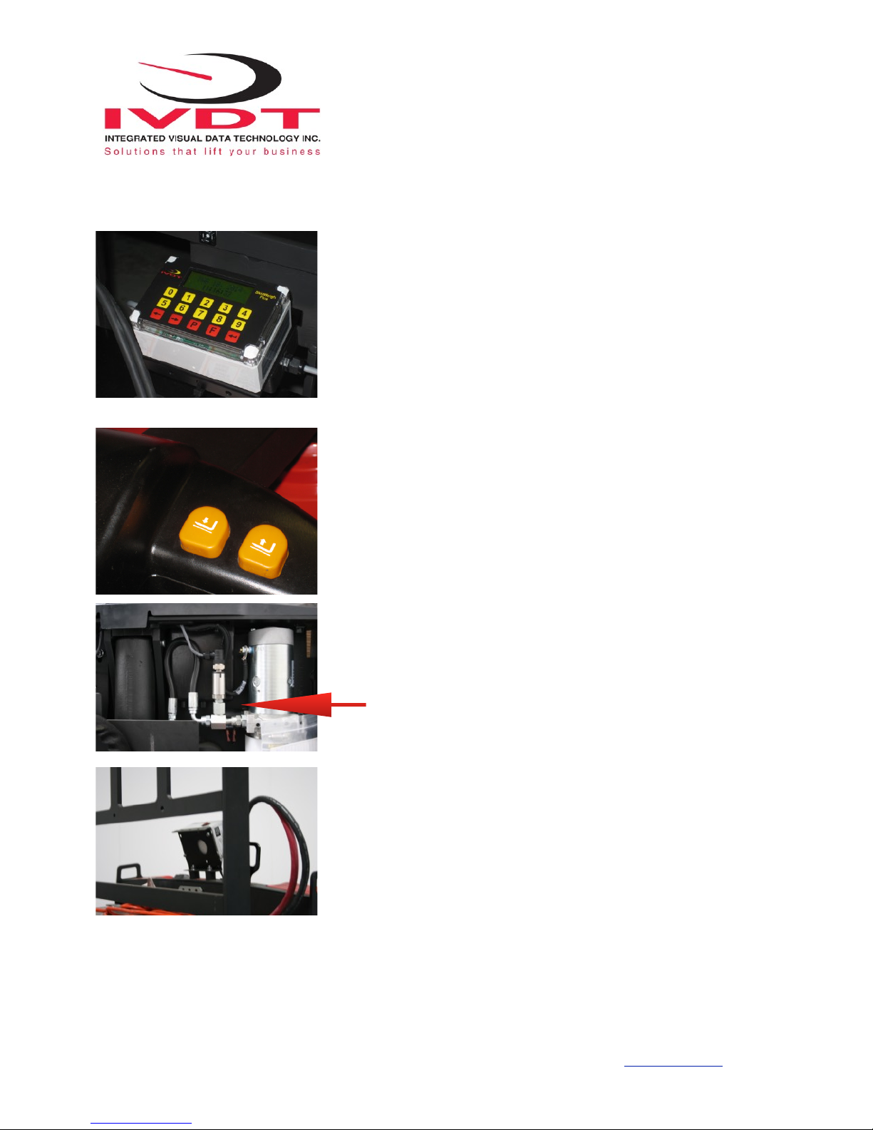
Overview of components
The standard ED3/ED4-EP SkidWeigh Plus check weighing system consist of two main components:
* Digital indicator with wiring harness, mounting bracket and anti-vibration mount
* Hydraulic pressure transducer with 3 wires cable
* Installation & calibration manual and operator usage instruction
Integrated Visual Data Technology Inc. 3439 Whilabout Terrace, Oakville, Ontario, Canada L6L 0A7 www.skidweigh.com
!
Operational principal
The ED3-EP and ED4-EP SkidWeigh Plus operational principal is based on
the hydraulic pressure transducer mounted in the vehicle lifting hydraulic circuit
and lift accurate technology. The load should be placed all the way in towards
the load back guard. With the load lowered to the ground the LCD display will
show time and date which is a starting point to initiate a load weight
procedure.
Operational Cycle
Operator must activate lift control switch and hold it until the loaded
forks are automatically stopped at the measurement height based on
the pressure transducer input signal. The increase in the hydraulic pressure
signal will initiate specific “weighing cycle” measurement algorithm for
activation of the lift accurate technology process that will automatically stop
lifted forks at predetermined height. As soon the loaded forks are stopped the
system will take a series of measurements and within 3-4 seconds the load
weight will be shown on LCD display. With load weight shown on LCD display
the system lift motor travel control will be enabled.
Pressure transducer installation
The pressure transducer must be installed in the lifting hydraulic line between
the lift control valve and lift cylinder(s).
Mount a T-piece in lifting hydraulic line.
Pressure transducer installation precautions
Before installation of the pressure transducer the hydraulic lift circuit must be
pressure free.
Pressure transducer has 1/4”-18 NPT male thread. Use thread seal to ensure
tight fit.
Selecting the mounting location for digital indicator
Note: Use the mounting bracket with the anti vibration mount and fasten
digital indicator on the vehicle dashboard. There are many examples of
mounting locations that will depend on the vehicle model. However, additional
mounting items such as a flat brackets may be needed to help secure digital indicator.
Integrated Visual Data Technology Inc. 3439 Whilabout Terrace, Oakville, Ontario, Canada L6L 0A7 www.skidweigh.com

!
Electrical connections
All SkidWeigh systems operate from 12 to 55 VDC.
- Orange Wire (+) Ignition switch On position
- Brown Wire (-) Battery negative
- Red Wire, connect to RED wire of the pressure transducer cable
- Black Wire, connect to BLACK wire of the pressure transducer cable
- White Wire, connect to WHITE wire of the pressure transducer cable
Two Black wires are connected to internal relay, dry contacts located in ED3/ED4-EP digital indicator. This internal relay
is controlled by the microprocessor and will be activated only during the load weighing cycle. The relay configuration is
SPST, normally closed NC contacts. 10 A current ratting
Pressure transducer
Power short circuit protection
All SkidWeigh systems are internally short circuit protected with resettable fuse. There is no need to install external inline
fuse in orange wire connected to the ignition switch.
Note: Any external devices connected to the SkidWeigh system, such as non standard onboard printer might require
external fuse.
Verification of the electrical connections done properly
Note: SkidWeigh weighing calibration function is not done at this stage. This test procedure is only to check if the
electrical connections of the system installation into the vehicle is done properly!
- Turn on vehicle power switch
- Lower forks to ground
- Turn on digital indicator power switch located on top of the housing
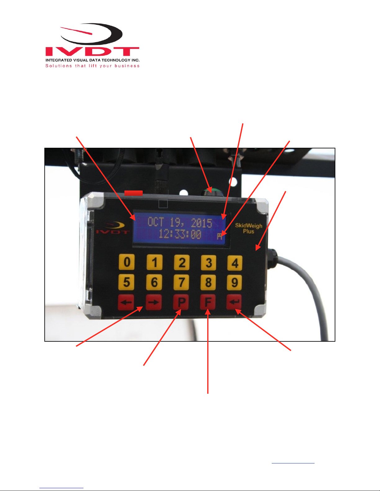
- Digital LCD display will be activated, showing software version and serial number
- Digital LCD display will show current date and time
LCD Display
Aug 28, 2010
12:20:23
Integrated Visual Data Technology Inc. 3439 Whilabout Terrace, Oakville, Ontario, Canada L6L 0A7 www.skidweigh.com
Male Port 1/4”-18 NPT

!
If the forks are lifted above the ground LCD digital display will show “PLEASE WAIT” and within few seconds display
will show “some” load weight . (Example: 455, not calibrated load weight at this stage)
If the above test is valid than the system electrical connections are done right.
The next procedure will be to log in the ADMINISTRATION MENU to calibrate the weighing function.
LCD Display
PLEASE WEIGHT
WEIGHT = 455
Integrated Visual Data Technology Inc. 3439 Whilabout Terrace, Oakville, Ontario, Canada L6L 0A7 www.skidweigh.com
!
Integrated Visual Data Technology Inc. 3439 Whilabout Terrace, Oakville, Ontario, Canada L6L 0A7 www.skidweigh.com
LCD Display
Special Functions Button
Bluetooth Icon
Keypad
“Enter key” ↵
Toggle Arrows Keys in set up menu
Print key or /and USB recording, wireless data SEND
FUNCTION MODE KEY
F 9 ADMINISTRATIVE MENU (Password protected)
F 0 OPERATOR MENU
*Bluetooth pairing *TARE set up * Part Count set up when applicable
Impact Monitoring
Mounting Bracket With Anti Vibration Mounts
Power Switch
 Loading...