

INTEGRATED SOLAR ASDX-65-40P, ASDX-80-E-32PX2, ASDX-80-E-40C, ASDX-65-40C, ASDX-65-48C Installation, Operation And Maintenance Manual
...
VERSION 2012.3.2


TABLE OF CONTENTS
DRAINBACK HEAT EXCHANGE SOLAR SYSTEM ................................................ 2!
INTRODUCTION ..................................................................................................................................... 2!
SYSTEM CONCEPT AND OPERATION DESCRIPTION .......................................... 3!
SRCC DISCLAIMER STATEMENT .......................................................................................................... 3!
OPERATION OF A DRAINBACK SYSTEM .............................................................. 4!
GENERAL CONSIDERATIONS ................................................................................ 5!
SOLAR COLLECTOR INSTALLATION .................................................................... 6!
COLLECTOR SIZING AND LOCATION ...................................................................................................... 6!
MOUNTING THE COLLECTORS ............................................................................................................... 7!
INSTALLER SUPPLIED COLLECTOR MOUNTING MATERIALS ...................................................................... 9!
COLLECTOR LOOP PLUMBING ............................................................................................................ 10!
PIPING RECOMMENDATIONS ................................................................................................................ 10!
SOLAR STORAGE TANK ....................................................................................... 11!
SUGGESTED MATERIALS FOR INSTALLING TANK ................................................................................. 11!
INSTALLER SUPPLIED MATERIALS FOR INSTALLING TANK .................................................................... 11!
INSTALLATION DETAILS FOR TANK ...................................................................................................... 11!
SOLAR STORAGE TANK LOCATION ..................................................................................................... 12!
PLUMBING FOR TANK INSTALLATION (SINGLE TANK SYSTEMS) ............................................................ 12!
TANK ELECTRICAL WIRING (SINGLE TANK SYSTEMS) .......................................................................... 13!
PLUMBING FOR TANK INSTALLATION (DUAL TANK SYSTEMS) .............................................................. 15!
PLUMBING FOR TANK INSTALLATION (SYSTEMS USING TANKLESS GAS WATER HEATER AS BACKUP) ..... 16!
DRAINBACK TANK INSTALLATION ..................................................................... 17!
SUPPLIED MATERIALS FOR DRAINBACK/HEAT EXCHANGER ................................................................. 17!
DBHX SIZE SELECTION CRITERIA ...................................................................................................... 17!
INSTALLER SUPPLIED MATERIALS FOR DRAINBACK/HEAT EXCHANGER ............................................... 18!
INSTALLATION OF DRAINBACK TANK ................................................................................................... 18!
SETTING THE CONTROLLER ................................................................................................................ 18!
PLUMBING THE DRAINBACK TANK ...................................................................................................... 19!
COMPLETING THE INSTALLATION ...................................................................... 20!

BASICS ABOUT THE DRAINBACK SYSTEM'S OPERATION .............................. 22!
COLLECTING THE SUN'S ENERGY ........................................................................................................ 22!
THE SYSTEM AT REST ........................................................................................................................ 22!
IN AN EMERGENCY.............................................................................................................................. 23!
FREEZE PROTECTION ......................................................................................................................... 23!
BEFORE CALLING FOR SERVICE .......................................................................................................... 24!
MAINTENANCE .................................................................................................................................... 24!
WHEN TO CALL FOR SERVICE ............................................................................ 25!
MODEL AND SERIAL NUMBER RECORDS: ............................................................................................ 25!
DRAINBACK/HEAT EXCHANGER SYSTEM WARRANTY ................................... 26!
EFFECTIVE DATE ................................................................................................................................ 27!
TROUBLE SHOOTING GUIDE ............................................................................... 28!
CONTROLLER OPERATION TEST .......................................................................................................... 28!
PREPARATION FOR TESTING ............................................................................................................... 28!
ON/OFF TEST ..................................................................................................................................... 28!
BASIC FUNCTION TEST ....................................................................................................................... 28!
TEMPERATURE VS. RESISTANCE CHART ............................................................................................. 29!
SENSOR CHECK ................................................................................................................................. 29!
TROUBLESHOOTING ACTION TABLE ........................................................................................ 30!

2
DRAINBACK HEAT EXCHANGE SOLAR SYSTEM
Introduction
Integrated Solar’s "DBHX" Drainback/Heat Exchange method of freeze protection is the
most reliable and safest type of system to use. The drainback system is a positive approach
to prevent freezing and scaling of the solar collectors, and to prevent overheating/stagnation
of the collector fluid in high temperatures and low usage situations. The drainback tank
contains a closed loop of water which circulates through the collector(s) and transfers the
energy to the storage tank located in the non-freezing environment of the house. The
drainback tank contains all of the water necessary to fill the collector loop while the
differential control operates the circulating pump. Gravity drains the water out of the
collector(s) and piping when the pump is off. The collector fluid is stored in the insulated and
protected drainback tank.
There are numerous advantages of a drainback system:
1. Beneficial in all climates
2. Power is not required for the drainback freeze protection to work.
3. Deep and prolonged freezes can be tolerated repeatedly.
4. The collector fluid will not stagnate in high temperature/low usage situations.
5. The closed loop protects collector fluid passages in hard water areas.
The key to a successful drainback system is proper installation. Proper installation requires
the collector supply and return lines be installed with sufficient slope to drain back to the
tank. Failure to observe this simple rule will circumvent the freeze protection offered by this
system concept. The ideal installation is to mount the collectors in a vertical orientation with
the transfer module lower than the collectors.
This manual refers to the following system model numbers:
Single Tank Systems Dual Tank Systems w/Electric
Using Solar Tank Water Heater for backup
With backup element ASDX-65-E-40P
ASDX-65-40P ASDX-80-E-40C
ASDX-65-40C ASDX-80-E-32PX2
ASDX-65-48C ASDX-120-E-40PX2
ASDX-80-40P
ASDX-80-40C Dual Tank Systems w/Gas
ASDX-80-32PX2 Water Heater for backup
ASDX-80-48P ASDX-50-G-24C
ASDX-80-48C ASDX-50-G-32P
ASDX-120-40PX2 ASDX-65-G-40P
ASDX-80-G-40C
Systems w/existing Electric ASDX-80-G-32PX2
Water Heater for storage ASDX-120-G-40PX2
and backup
ASDX-50-24C Systems w/Tankless Gas
ASDX-50-32P Water Heater for backup
ASDX-80-TLG-40C
3
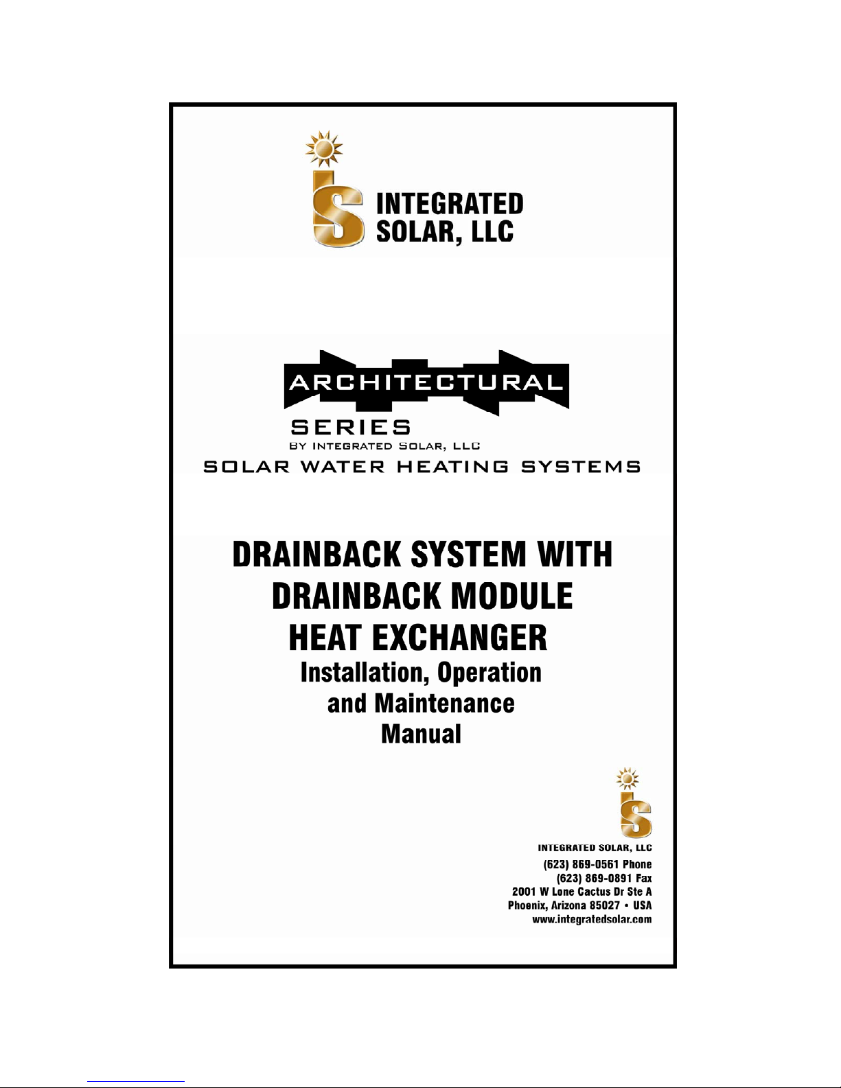
SYSTEM CONCEPT AND OPERATION DESCRIPTION
A diagram of a typical Drainback system is shown in Figure 1.1. A detailed list of Integrated
Solar’s supplied components and typical installer supplied components is provided in the
related sections of this document.
Collector circuit can be all ¾” copper tubing; if using PEX use only where shown in diagram.
Drainback System Conceptual Drawing Only
Figure 1.1
SRCC Disclaimer Statement
The solar energy system described by this manual, when properly installed and maintained,
meets the minimum standards established by the SRCC. This certification does not imply
endorsement or warranty of this product by SRCC.

4
OPERATION OF A DRAINBACK SYSTEM
The operation of a Drainback System is simple. Whenever the collector sensor reaches a
temperature 16"! to 24º F higher than the water at the bottom of the storage tank, the control
turns on the pumps. The first pump circulates the water stored in the drainback (DBHX)
storage tank through the solar collector. The water increases in temperature and is
returned to the drainback storage tank, bathing the copper coil heat exchanger in solar
heated water. The second pump circulates water from the storage tank through the copper
coil heat exchanger which transfers the heat from the collector to the storage tank. This
process continues until the collector temperature sensor is within 4º F of the storage tank
temperature sensor, or the storage tank reaches the pre-set high temperature limit, at which
time, the control unit turns the pumps off. The water in the collector loop then drains back
into the insulated DBHX tank where it remains until the collector temperature again reaches
16" to 24º F higher than the storage tank.
Freeze protection is automatic. When the control has turned the pumps off, the water in the
collector loop drains back into the DBHX storage tank. If freezing conditions occur, there is
no water in the collectors or piping to freeze and, therefore, no damage occurs.
Overheating and stagnation of the collector fluid is also automatically avoided, because the
water in the collector loop also drains back into the DBHX storage tank when the hot water
storage tank is fully heated
The primary advantage of the drainback system is that it is fail safe and can be used
anywhere. Loss of power does not disable the freeze protection, nor does any other
probable malfunction.
The key to the installation of a drainback system is to provide the proper pitch in both the
supply and return lines that connect the collector array and the DBHX reservoir tank. The
water will drain back through the pump, but to do so, air must go up the return line. Proper
sloping in all lines and the collector array, with the avoidance of water traps in the supply
line, are required to provide the drainback feature.

5
GENERAL CONSIDERATIONS
All installations must conform to local building code requirements especially for penetrating
structural members and fire-rated assemblies.
The design and installation of the system must not impair emergency movement of the
building occupants.
Do not install the collectors on a roof which already needs repairs. Keep a safe distance
from roof vents, chimneys, skylights, etc.. Take special precautions to prevent damage to
tile, shake and slate roofs.
Be sure the collector(s) are not shaded by external obstructions more than the specified
period allowed in the site design
The location, orientation, and position of the collector(s) relative to nearby objects and
surfaces shall be such that water run-off from the collector surface is not impeded. In
climates where snow may collect on the roof, excessive build-up of snow on lower portions
of the collector glazing shall not be permitted to occur. Collectors should be mounted as
close to the peak as practical on smooth roof surfaces like metal roofs and as close to the
lower edge as practical on rougher roof surfaces like asphalt shingles.
Penetrations of the building through which piping or wiring is passed shall not reduce or
impair the function of the enclosure. Structural components penetrated by solar system
components must meet applicable codes. Penetrations through fire-rated assemblies shall
not reduce the building’s fire resistance required by local codes, ordinances, and applicable
standards. Penetrations through wall or other surfaces shall not allow intrusion by insects
and/or vermin. Required roof penetrations shall be made in accordance with applicable
codes and also by practices recommended by the National Roofing Contractors Association.
Be sure any caulking and/or sealant is recommended for use on the surface(s) to which it is
applied.
Building materials adjacent to solar components should not be exposed to elevated
temperatures. Insulation in the sides and back of the collectors protect adjacent materials
from heat produced by the collector, pipe insulation must be installed to protect materials
from the heat of the collector loop piping. Insulation around the drainback tank and pipe
insulation serve to protect adjacent materials from the heat of the solar heated water. Be
sure to position the drainback module so that the pumps are not too close to walls or other
building materials, and so that the pumps are isolated from public traffic areas.
Filled Weights of Integrated Solar components
AS406C Collector 89 lbs
AS406C Collector 92 lbs
AS408P Collector 120 lbs.
AS408C Collector 121 lbs.
AS410P Collector 146 lbs.
AS410C Collector 151 lbs.
AS412P Collector 174 lbs.
AS412C Collector 179 lbs.
DBHX08 Drainback Module 117 lbs.
DBHX12 Drainback Module 164 lbs.
Temperature and Pressure Ratings of Integrated Solar components
All Collectors Maximum Operating Temperature 230" F.
Maximum Operating Pressure 30 PSI (in drainback loop)
Test Pressure 150 PSI
Drainback Modules Maximum Operating Temperature 230" F.
Maximum Operating Pressure 30 PSI (in drainback loop)
Maximum Operating Pressure 125 PSI (in Heat Exchanger loop)

6
SOLAR COLLECTOR INSTALLATION
Locate all collectors for accessibility and check the proposed roof area for compatibility.
Collectors must be located for a southerly orientation. The best location for the solar
collectors is one that provides a day-long shadow-free view of the southern sky.
Determine which manifold ends of the collector or array are to be used for the inlet and
outlet connections; the inlet at the bottom and the outlet at the top. The inlet and outlet must
be at diagonally opposite corners of the collector or array, to insure balanced flow. The
collector outlet side should be the side closest to the tank to minimize the return pipe length.
Consider the best access to the roof and internal access for attic work. Plan routes to be
used and prepare the clearances. Plan the piping runs for the least number of bends and
fittings while maintaining a minimum 1/4" per foot slope in horizontal runs.
Collector Sizing and Location
The Architectural Series collector array is typically made up of one or two collector panels
plumbed together. It is possible to plumb up to a maximum of five collectors together for a
residential Domestic Hot Water (DHW) application. It is recommended that the array be
mounted with the waterways in the vertical position (up the slope of the roof) in all cases.
Collectors mounted horizontally may not drain properly.
Select the collector array location and determine the inlet roof penetration. Locate the rafters
to which the array will be mounted and mark with a chalk line.
From the inlet pipe location, strike a horizontal line a minimum of 10 feet. Make certain there
are no dips or sags in the roof which may prevent the collector from draining. To insure
complete drainage for the solar energy system, the vertical collector array must be installed
with a minimum vertical drop towards the inlet of 1/4" per foot of collector header. Lay out
the collectors at the proposed location and place a 2 foot (min.) level on the collector near
one edge of the glazing and parallel with the ends. Orient the collector array so that the
bubble indicates the proper slope. Make certain there is no trap in the collector supply pipe
from the roof jack to the collector.

7
Mounting the collectors
Collectors can be mounted either parallel to a pitched roof surface, or, using a Panel Tilt Kit,
on a flat roof or on a pitched roof at a steeper angle than the roof slope. Any alternate
mounting method must be capable of maintaining tilt and azimuth to design conditions.
To mount collectors parallel to a pitched roof, use kit #ASZ1 or #AS1 for a single collector,
Kit #ASZ2 or #AS2 for 2 collectors side by side, or Kit #ASZ3 or #AS3 for 3 collectors side
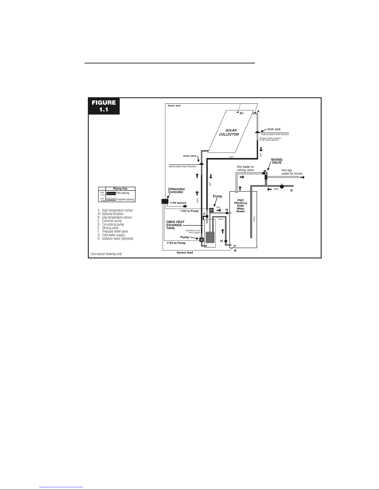
by side. Figure 2.1 shows several acceptable methods for attaching the Solar Strut to the
roof structure; local codes may dictate which method to use. CAUTION: NEVER LAG INTO
THE ROOF SHEATHING ONLY.
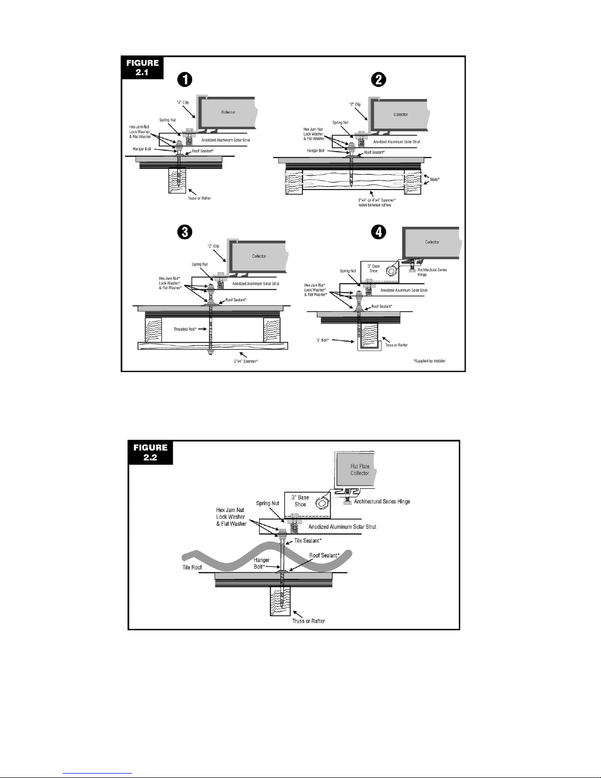
For barrel or “S” shaped concrete tiles, remove one tile at each penetration point and attach
a hanger bolt, threaded rod or “J” hook as shown in Figure 2.1. Use a long enough fastener
so that it extends above the top (“peak”) of the tile. Drill a hole in the tile so the fastener can
extend up through the tile when it is replaced. The strut should be above, not touching, the
top of the tile. See Figure 2.2. Although the tile is not the waterproof portion of the roof, it’s
still a good idea to seal where the fastener extends through the tile with an appropriate
sealer.
For metal roofs, use fasteners recommended by the roof manufacturer to attach the Solar
Strut.
To mount collectors using the Architectural Series Tilt Kit, first determine the length of the
riser needed to achieve the desired angle for the installation. Use one Panel Tilt Kit per
collector. Use Kit #ASTKXX5 (where “XX” is the riser length) if you wish to attach the 5”
base shoes directly to the roof as shown on the left hand side of Figure 2.3. Use Kit
#ASTKXX3 if you wish to attach the 3” shoes to Solar Strut as shown on the right side of
Figure 2.2 (for multiple collectors, the Solar Strut method is usually easier). Attach the 5”
shoes or the Solar Strut to the roof in one of the ways shown in Figure 2.1. CAUTION:
NEVER LAG INTO THE ROOF SHEATHING ONLY.
All collector installations must allow for a 2" minimum clearance between the back of the
collector and the roofing material.
8
Figure 2.1
Methods of attaching to the roof structure
Figure 2.2
Mounting above concrete tile

9
Figure 2.3
Panel Tilt Kit showing both 5” shoes directly on the roof and 3” shoes on strut
Suggested collector materials for installation
Integrated Solar’s drainback solar water heating systems will require the following parts to
attach to the Drainback Module and complete the system:
A. Collector panel with sensor
B. Collector panel(s) if more than one required
C. Appropriate mounting kit for the roof type and slope.
D. 2 - 3/4" unions or couplers for connecting supply and return pipes to collectors
E. 2 - 1" x 3/4" reducing adapter for header connections
F. 2 - 1” Copper Caps to cap header ends not being used
G. 2 - 1" C x C unions or couplers per additional collector if more than one required
H. 2 - flashings for roof plumbing penetrations
Installer supplied collector mounting materials
The installer must bring the following components to the roof to properly install the
Architectural Series solar collector array.
A. Lag screws or bolts (and nuts) and washers
(length and size to be compatible with the local conditions and roof type)
B. Flux
C. Lead free solder
D. Sealing and caulking materials
E. Pipe insulation having an R2.6 or higher rating, such as Insul-Tube® with
at least a 1/2” wall thickness, and weather proof coating for exposed insulation.
F. Pipe supports
G. 1" stainless steel hose clamp
H. Wire nuts
I. #18/2 shielded wire (rated for outdoor use).

10
Collector Loop Plumbing
The collector loop must be Type M or Type L 3/4” copper tubing (PEX may be used only
where shown in Figure 3.1 or Figure 4.1) and must be continuously sloping downward (at
least 1/4" per foot) toward the drainback tank.
Piping recommendations
A. Collector circuit can be all 3/4” copper tubing. If using PEX, use only where shown in
Figure 3.1 or Figure 4.1; the PEX must not be exposed to sunlight, and you must use
36” of uninsulated copper from both the collector inlet and outlet before converting to
PEX.
B. Clean and flux all sweat joints before soldering. Use only 95/5 or approved lead free
solder in the collector loop.
C. Plumb all solar loop lines on 3" minimum centers to accommodate pipe insulation.
D. Use pipe insulation having an R2.6 or higher rating, such as Insul-Tube® with at
least a 1/2” wall thickness. All collector loop piping must be insulated, except the 36”
of uninsulated copper from both the collector inlet and outlet if you are using PEX.
E. Slip insulation over straight runs before soldering, keeping 6" clear of all joints for
soldering and leak detection. Insulation exposed to sunlight should be painted with a
UV resistant latex paint or wrapped in aluminum foil duct tape.
F. Secure all piping with adequate pipe hangers and straps in order to insure proper
support and drainage slope of at least 1/4" per foot. Supports must not compress the
insulation.
G. Be careful not to pinch or cut the sensor wire insulation, especially where it enters
the roof flashing, goes through the ceiling, or where it is supported. Sensor wire
used outside must be rated for outdoor use and protected from ultraviolet radiation.
H. Hard water conditions can result in sediment in the storage tank and within the
drainback tank loop. A water softener or filter should be used to protect the solar
energy system.
CAUTION
Air Vents should not be installed on DBHX system collector loop

11
SOLAR STORAGE TANK
Integrated Solar does not manufacture Solar Storage Tanks. For a single tank system,
always use a solar storage tank with a backup element that is listed and labeled by an
accredited listing organization, such as Underwriter’s Laboratories Inc.®. For either a dual
tank system or a system with a tankless gas water heater backup, always use both a solar
storage tank and a backup water heater that is listed and labeled by an accredited listing
organization, such as Underwriters Laboratories, Inc.®. For a system using an existing (or
new) 50 gallon electric tank as both storage and backup, always use an electric water
heater with a backup element that is listed and labeled by an accredited listing organization,
such as Underwriter’s Laboratories Inc.®.
Water heaters with an insulation rating of less than R-12 should have an exterior insulation
blanket installed to provide a minimum insulation rating of R-12.
Suggested Materials for Installing Tank
A. Solar storage tank with electric element backup (Dual Tank Systems do not require
the electric element backup in the tank, the backup heating is provided by the
existing gas or electric water heater.)
B. Plumbing components
2 - 1/2" ball valves (optional)
1 - tank earthquake strap set (if required)
2 - 3/4" x 1/2" dielectric unions
2 - 3/4" x 18" (or other length as required) water flex connectors
1 - 3/4" mixing valve (120 to 160 degrees F.)
1 - 150 psi, 210 degrees F. (T & P) relief valve
2 – In Line Thermometers (Only 1 for Dual Tank Systems)
3 – 3/4" 2 way ball valves (Dual Tank Systems only)
1 - Brass 3/4” FIP Tee (only for systems using 50 gallon Electric
Water Heater for both storage and backup (ASDX-50-24C
and ASDX-50-32P))
1 – Brass 3/4" X CLOSE Nipple (only for systems using 50 gallon Electric
Water heater for both storage and backup (ASDX-50-24C
and ASDX-50-32P))
C. Tank installation Instructions
Installer Supplied Materials for Installing Tank
A. #18/2 bell or shielded wire (rated for outdoor use)
B. Wire nuts (4)
C. Silicone Sealant
D. 95-5 or approved lead-free solder
E. Flux
F. 1/2" and 3/4' copper pipe
G. Misc. copper fittings
H. Pipe insulation having an R2.6 or higher rating, such as Insul-Tube® with
at least a 1/2” wall thickness, and weather proof coating (as required)
I. #14 gauge wire and conduit (tank power and ground)
Installation Details for Tank
Single tank systems are recommended for applications where electric water heaters are
existing. Dual tank systems with electric backup may be used to increase capacity for large
usage. Dual tank systems with gas backup are used when gas will be providing the backup.
All piping and component installation must conform to local and state codes.

12
Solar Storage Tank Location
The storage tank should be located, whenever possible, in the same location as the old
water heater, since the electrical and plumbing connections will already exist. Position the
tank in a place where it can be accessed for service and maintenance. Water heater tanks
located in or above the living space shall be installed on a drip pan with a drain line to a
waste line or outside or have other means to safely remove any excess liquid.
Plumbing for Tank Installation (Single Tank Systems)
Follow these instructions and refer to Figure 3.1 (See Figure 3.3 for 50 Gallon Electric Water
heater being used as storage and backup):
A. Turn off the cold water feed to the existing water heater. Ensure that the existing
shut off valve is working correctly, and repair or replace it if necessary.
B. Remove old water heater
C. Set the new storage tank on a solid floor foundation and use shims as needed to
level it.
D. Position the tank so that the two inspection covers and drain valve are accessible.
Building materials adjacent to solar components should not be exposed to elevated
temperatures.
E. Install the supplied pressure and temperature relief valve with a 3/4" drain line to
discharge no higher than 6" from the floor, or as required by local codes.
WARNING
F. Install a tempering (mixing) valve to reduce the possibility of scalding injury to the
system users. The tempering valve must allow a range of selectability of at least
10"C (18"F) and must include a set point of 50"C (122"F).
WARNING
G. It is recommended that the cold water feed line to the mixing valve be connected to
the bottom of the valve in order to avoid unwanted thermosyphon or possible
damage to certain types of mixing valves. A heat trap is required for the hot side of
the Watts 70A mixing valve. See manufacturer’s instructions.
CAUTION
H. Install the cold and hot water lines to the tank. Dielectric unions are not required in
all code jurisdictions, however, they are a good idea since the nipples supplied with
most tanks are not a dielectric connection.
I. Insulate all hot water lines, and the final 5 feet of the cold water feed line (or all the
exposed cold water feed line if less than 5 feet is exposed from the wall to the tank)
with pipe insulation having a minimum R2.6 value, such as Insul-Tube® with at least
a 1/2” wall thickness.
Avoid heat damage to the tempering valve.
Remove the thermostatic assembly before soldering.
Once the tem
p
ering valve has cooled, reinstall the valve assembly.
T & P relief valve discharge line
must not be blocked or reduced in size.
An approved tempering valve must be used in
the hot water line to the house.

13
Collector circuit can be all 3/4” copper tubing; if using PEX use only where shown in diagram.
Figure 3.1
SINGLE TANK SYSTEM
Tank Electrical Wiring (Single Tank systems)
WARNING
The wiring diagram for the electrical element is located on the inside of the upper access
cover or in the water heater installation instructions. Also see Figure 3.2.
On a 50 gallon electric tank being used for both storage and backup (Systems ASDX-5024C and ASDX-50-32P), set the thermostat at 80" F on the lower heating element. Leave
the upper thermostat at about 125" so it will operate as the backup.
WARNING
To avoid fatal shock hazard shut off main power supply
before beginning.
Lock and red tag the box to prevent accidental connection of power.
For 110 volt A.C. connections,
turn off power to circuit to which connection is to be made.
Do not turn on power to electric element until tank is full of water.
Failure to follow this instruction will burn out the element and
void the tank manufacturer’s warranty.

14
Figure 3.2
Water Heater Electrical Schematic
WARNING
Figure 3.3
FIFTY GALLON ELECTRIC WATER HEATER AS STORAGE AND BACKUP
WATER HEATER MUST BE GROUNDED.
CONNECT A #14 (MIN.) GAUGE WIRE FROM A SUITABLE GROUND SOURCE
TO THE GROUND TERMINAL OF THE WATER HEATER.

15
Plumbing for Tank Installation (Dual Tank Systems)
Follow these instructions and refer to Figure 4.1:
A. Turn off the cold water feed to the existing water heater. Ensure that the existing
shut off valve is working correctly, and repair or replace it if necessary.
B. Locate the solar storage tank as close as possible to the existing water heater.
C. Set the new storage tank on a solid floor foundation and use shims as needed to
level it. Water heater tanks located in or above the living space shall be installed on
a drip pan with a drain line to a waste line or outside or have other means to safely
remove any excess liquid.
D. Position the new storage tank so that the two inspection covers and drain valve are
accessible. Building materials adjacent to solar components should not be exposed
to elevated temperatures. In a dual tank system, do not connect any element(s) in
the solar storage tank to electrical power. Backup heat is provided by the second
(existing) electric or gas water heater.
E. Install the supplied pressure and temperature valve with a 3/4" drain line to
discharge no higher than 6" from the floor, or as required by local codes.
WARNING
F. Install a tempering (mixing) valve to reduce the possibility of scalding injury to the
system users. The tempering valve must allow a range of selectability of at least
10"C (18"F) and must include a set point of 50"C (122"F).
WARNING
G. It is recommend that the cold water feed line to the mixing valve be connected to the
bottom of the valve in order to avoid unwanted thermosyphon or possible damage to
certain types of mixing valves. A heat trap is required for the hot side of the Watts
70A mixing valve. See manufacturer’s instructions
CAUTION
H. Install the cold and hot water lines to the tank. Install 3 3/4" 2 way ball valves as
shown in Figure 4.1 to allow the solar storage tank to be bypassed if ever necessary.
Install an in line thermometer in the line between the “Hot” outlet of the solar storage
tank and the “Cold” inlet of the backup tank. Dielectric unions at the tank
connections are not required in all code jurisdictions, however, they are a good idea
since the nipples supplied with most tanks are not a dielectric connection.
I. Insulate all hot water lines, and the final 5 feet of the cold water feed line (or all the
exposed cold water feed line if less than 5 feet is exposed from the wall to the tank)
with pipe insulation having a minimum R2.6 value, such as Insul-Tube® with at least
a 1/2” wall thickness.
If you are replacing the existing electric or gas water heater, follow the water heater
manufacturer’s instructions, and conform to all applicable local codes for the water heater
installation as well as the solar system installation.
Avoid heat damage to the tempering valve.
Remove the thermostatic assembly before soldering.
Once the tempering valve has cooled, reinstall the valve assembly.
T & P relief valve discharge line
must not be blocked or reduced in size.
An approved tempering valve must be used
in the hot water line to the house.

16
Collector circuit can be all 3/4” copper tubing; if using PEX use only where shown in diagram.
Figure 4.1
DUAL TANK SYSTEM
Plumbing for Tank Installation (Systems using Tankless gas water heater as
backup)
Follow all the instructions under Dual Tank Systems, and refer to Figure 4.2. Be sure that
the tankless water heater senses the temperature of the incoming water, so that it will not
turn on if the solar system is supplying hot enough water. Refer to the tankless water heater
manufacturer’s instructions and specifications.
Figure 4.2
TANKLESS GAS WATER HEATER AS BACKUP

17
DRAINBACK TANK INSTALLATION
Supplied Materials for Drainback/Heat Exchanger
Separate all parts from packing material and check each one with the illustration and the
listing below to make certain all items are accounted for before discarding any packing
material.
Transfer module (drainback heat exchanger tank with integral pumps (2), and controller with
power cord)
10K sensor for collector (if the sensor is not already installed on the collector).
10K sensor for Storage Tank
Installation Manual (Includes Troubleshooting Guide)
Figure 5.1
DRAINBACK MODULE
DBHX Size Selection Criteria
The Integrated Solar drainback heat exchange module comes in two sizes: an eight gallon
unit and a twelve gallon unit. The eight gallon model should be used in applications utilizing
64 square feet or less of collector area and a maximum total pipe length of 155 feet with 3/4"
piping, or for 80 or 96 square feet of collector area and a maximum total pipe length of 95
feet. The twelve gallon model should be used in applications with a collector array of 80 or
96 square feet with system piping up to 155 total length, or for 64 square feet or less of
collector area with system piping up to 215 feet total length. In the event the collectors are
to be installed higher than 25 feet above the DBHX tank, a booster pump is required and the
factory should be consulted. Consult the factory if there are any questions concerning
proper drainback tank sizing or selection.

18
Installer Supplied Materials for Drainback/Heat Exchanger
The installer must bring the following components to the area where the drainback tank is to
be installed in the drainback system:
A. 95/5 solder or approved lead free solder
B. Flux
C. Grounded 115 VAC outlet
D. Misc. 1/2" and 3/4" copper fittings and hard copper to connect the transfer
module with the collector array and the storage tank
E. 18/2 shielded wire for connecting sensors to the control
F. Pipe insulation having an R2.6 or higher rating, such as Insul-Tube® with
at least a 1/2” wall thickness, and weather proof coating (as required)
G. Funnel with 1/2" opening and bucket to measure water fill
(3/8" tubing may be used to siphon fluid to drainback tank)
H. 3/4” MIP Hose Bib or 3/4” brass plug for drain port tee.
I. 30 psi pressure relief valve, or adjustable pressure relief valve set to 30 psi
Installation of Drainback Tank
The module should be located as close as possible below the collectors to provide best
drainage results. Maintain access to pumps, control and drain port. Building materials
adjacent to solar components should not be exposed to elevated temperatures. Insulation
around the drainback tank and pipe insulation serve to protect adjacent materials from the
heat of the solar heated water. Be sure to position the drainback module so that the pumps
are not too close to walls or other building materials, and so that the pumps are isolated
from public traffic areas.
CAUTION
Setting the Controller
Refer to Figure 5.3 for controller settings behind the removable panel on the controller
A. Install the supplied storage sensor in the bottom of the solar storage tank.
B. Connect the storage sensor wire to the control at terminals 1 and 2, labeled “Tank”.
See Figure 5.2
C. Connect the collector sensor to the control at terminals 3 and 4, labeled “Solar”. See
Figure 5.2.
D. Set the “Turn On” differential (Top Dial) to 24º F (All the way clockwise).
E. Set the “Hi Limit” (Bottom Dial) to the desired setting, typically 140º to 160º F. The
High Limit is the temperature at the bottom of the solar tank which will turn off the
solar water heating system. For Gas Backup Systems, set the High Limit no higher
than 140º F. You may set the High Limit lower if the household hot water usage is
expected to be low (few people in the home), or, for Electric Backup systems, higher
if usage is expected to be high (large family size, large bathtub(s), frequent guests,
etc).
DO NOT INSTALL ANY TYPE OF AIR VENT ON THE
COLLECTOR/DRAINBACK TANK LOOP.
CONSTANT INFLUX OF NEW OXYGEN
WILL CAUSE THE DRAINBACK TANK INTERIOR TO RUST
The module must not be installed in an area
where it is subject to freezing.
We do not recommend installing the module higher than
the top of the storage tank unless space considerations require it.
Do not install the module less than two feet below the bottom header
of the collectors to insure adequate drainback..

19
CAUTION
F. Set the “On-Auto-Off” slide switch to “Auto”. In “Auto,” the controller will turn on the
pumps only when there is heat available from the sun and the tank needs heat. In
“On,” the controller will operate the pumps continuously, and in “Off,” the controller
will keep the pumps off all the time.
Figure 5.2
Setting the Controller
Plumbing the Drainback Tank
(Refer to Figure 5.3 for drainback module connections and filling procedures.)
A. Install the 3/4” MIP hose bib or 3/4”brass plug in the drain port tee.
B. Connect the collector supply to the outlet of the lower pump at the dielectric union.
C. Fill drainback tank to the fill union using the funnel or siphoning hose. Fill until the
fluid level is at the fill union using potable water.
D. Connect the collector return to the drainback module at the fill union.
E. Connect the storage supply line to the module at 1/2" union and to the 1/2" ball valve
and dielectric union at the tank port. On a side connect tank, the storage supply port
is the lower port. On a top connect tank, the supply port may be labeled “To Solar”,
To Collector”, “Pump Suction”, etc. On a 50 gallon electric tank being used for both
storage and backup (Systems ASDX-50-24C and ASDX-50-32P), use a 3/4” Tee to
connect to the cold water feed directly above the tank (See Figure 3.3) On a dual
tank system using a 50 gallon tank as storage (Systems ASDX-50-G-24C and
ASDX-50-G-32P), use a 3/4" Tee and nipple to connect between the tank drain port
and tank drain valve.
F. Connect the storage return to the pump at 1/2" union and to the 1/2" ball valve and
dielectric union at the tank port. On a side connect tank, the storage return is about
the middle of the tank. On a top connect tank, the storage return may be labeled
“From Solar” “From Collector”, “Pump Discharge”, etc.. On a 50 gallon electric tank
being used for both storage and backup (Systems ASDX-50-24C and ASDX-50-
32P), connect both the return line and the T & P Relief Valve to a 3/4" FIP Brass Tee
fitted to the T & P Relief Valve port on the water heater (See Figure 3.3). On a dual
tank system using a 50 gallon tank as storage (Systems ASDX-50-G-24C and
ASDX-50-G-32P), use a 3/4" Tee to connect to the cold water feed line into the tank.
G. On a single tank system, install an in line thermometer in both the storage supply
and the storage return lines as shown in Figure 3.1 or Figure 3.3.
H. Fill the solar storage tank and check entire system for leaks.
I. Plug in the control and test system.
J. Unplug control. Open drain below collector pump and drain tank. This process has
flushed the collector loop of flux and debris.
ALWAYS SET THE CONTROL HIGH LIMIT SETTING
LOWER THAN THE TANK MANUFACTURER’S HIGH TEMPERATURE LIMIT

20
K. Refill drainback tank and plug in control. Use only potable, distilled, or de-ionized
water in the DBHX.
Figure 5.3
Plumbing the Drainback Tank
COMPLETING THE INSTALLATION
If the sun is shining when you finish the installation, the pumps should be operating and the
system should be collecting heat. Check all your plumbing connections to insure that there
are no leaks. If the sun is not shining, turn the control to “On” long enough to check for
leaks, then return the switch to “Auto”.
Label the drain and fill valves and major components using the labels in the System Label
Kit #LABELDBSYS (and #LABELDBDUAL for dual tank systems) or make your own
permanent labels using the information in Figure 6.1. Locations for the labels are shown in
Figure 6.2.
Double check all areas where you penetrated the roof and walls to be sure each area is
sealed. Be sure all the pipes are insulated and that pipe insulation has been painted or
taped where it is exposed to sunlight. Be sure all pipes are completely supported to avoid
sagging, and that all horizontal pipe runs slope downward at least 1/4" per foot.
Be sure to collect all your tools and clean up the work area thoroughly.
Fill in the Installing Company’s name, address and phone number in this manual and leave
it with the homeowner. Review the operation of the system with the homeowner, paying
particular attention to the location and operation of the mixing valve, the location and
operation of the cold water supply shut-off valve, the location and operation of the bypass
valves on a Dual Tank system and the “In An Emergency” instructions in this manual.

21

22
BASICS ABOUT THE DRAINBACK SYSTEM'S OPERATION
Collecting the Sun's Energy
When the temperature of the collector sensor in the array reaches a temperature 16" to 24º
F higher than the temperature of the water near the storage sensor, the control turns on
both pumps. The water in the DBHX module is circulated through the solar collector array on
the roof, where it is heated by the sun, and returned to the DBHX module. At the same time,
water near the bottom of the storage tank (the coldest part) is pumped through the heat
exchanger and returned near the middle of the storage tank, closer to the hot water outlet on
the tank. This continues as long as the solar collector array remains at least 4º F above the
temperature of the water at the bottom of the tank and the storage tank temperature at the
bottom does not exceed the high temperature limit protection setting.
There are three small lights on the bottom right hand side of the control, labeled “POWER”,
“1” and “2”. See Figure 5.4. The “POWER” light indicates that the control is plugged in and
has power. Only the “POWER” light will be on if there is no heat available from the sun, or if
the solar system has already heated the storage tank. Both the “POWER” and “1” lights will
be on when the system is operating and collecting heat. The “2” light should never be on for
a drainback system.
For single tank systems compare the temperatures of the two thermometers on the
drainback supply and solar storage return pipes when the pumps are running on a clear
sunny day. The return line temperature (the return line is the line between the pump on the
top of the Drainback Module and the storage tank) should be about 3" to 5" warmer than the
supply line temperature when the pumps are running.
For dual tank systems check the temperature on the thermometer in the pipe leaving the
solar storage tank at the end of a clear, sunny day. A hot water tap must be opened to get a
correct reading. The temperature should be above100º! F. if little hot water was used during
the day.
Figure 5.4
Control Lights
The System At Rest
As night approaches, or inclement weather moves in, the solar collector temperature will
drop to less than 4º F above the storage tank temperature. This causes the control to turn
off both pumps. The control will also turn off the pumps when the bottom of the tank reaches
the Hi Limit temperature setting. When the pumps turn off, bubbles of air from the DBHX
module travel up the solar collector return pipe, breaking the vacuum. This forces all of the
water in the solar collector array and its piping to drain safely back into the reservoir. The
back-up heater element in the storage tank then provides any additional heating to maintain
a minimum water temperature of 120º F.
The system operation is similar for a dual tank system, the only major difference being the
back-up heating is done by the second (existing) tank.

23
In an Emergency
If there is a leak in the collector, the drainback tank, or the pipes to the collector, unplug the
controller and call your service dealer.
If there is a leak in the solar storage tank, backup tank, or plumbing, close the cold water
supply valve, unplug the controller, turn off the circuit breaker that controls the hot water
heater, or turn off the gas supply valve if it is a gas water heater and call your service dealer.
In a dual tank system, if the emergency affects only the solar storage tank; unplug the
controller and turn the bypass valves to bypass the solar storage tank.
Extended Period Shut-down and Start-up Procedures
If you plan to be gone for an extended period of time, it is not recommended that you shut
down your system. As long as the power remains on, the system will operate only as
needed to maintain the hot water temperature, and you’ll have hot water available as soon
as you return.
If, for some reason, the system must be shut down for an extended period you must follow
these procedures and cautions.
A. To shut down the drainback system, simply unplug the control.
B. To shut down the backup hot water system, turn off the circuit breaker that controls
the hot water heater, or turn off the gas supply valve if it is a gas water heater.
C. In addition, if the area where the drainback module and storage tank are located may
be subjected to freezing temperature, completely drain the drainback tank, storage
tank and piping.
D. To start up the backup hot water system, turn the water supply on; be sure the tank
is filled by turning on a hot water faucet until the water flow is steady. Then turn the
circuit breaker back on. For a gas water heater, follow the water heater
manufacturer’s instructions for start-up, or call a qualified service technician.
E. To start up the drainback system, simply plug in the differential control (if the
drainback tank was drained, it should be refilled first following the installation
instructions in this manual). After a few minutes, if the sun is shining, you will hear
water being pumped to the collector(s) from the drainback tank. If not, refer to the
servicing section.
Freeze Protection
Freeze protection of the collector(s) is automatic in a properly installed drainback system.
Whenever the collectors are not warmer than the bottom of the storage tank, there is no
circulation and water drains from the collector(s) into the drainback module. If the area
where the drainback module and storage tank are located may be subjected to freezing
temperature, unplug the controller, turn off the circuit breaker to the backup electric
element(s), turn off the gas supply valve to a gas water heater, and completely drain the
drainback tank, storage tank and piping.
The Architectural Series Drainback Solar Water Heating System has a freeze tolerance limit
of -60º F (60º F below zero" F) ambient air temperature. Freeze tolerance limits are based
on an assumed set of environmental conditions. Extended periods of cold weather,
including ambient air temperatures above the specified limit, may cause freezing in exposed
parts of the system. It is the owner’s responsibility to protect the system in accordance with
the Supplier’s instructions if the air temperature is anticipated to approach the specified
freeze tolerance limit.

24
Before Calling for Service
For single tank systems compare the temperatures of the two thermometers on the
drainback supply and solar storage return pipes when the pumps are running on a clear
sunny day. The return line temperature (the return line is the line between the pump on the
top of the Drainback Module and the storage tank) should be about 3" to 5" warmer than the
supply line temperature when the pumps are running.
For dual tank systems check the temperature on the thermometer in the pipe leaving the
solar storage tank at the end of a clear, sunny day. A hot water tap must be opened to get a
correct reading. The temperature should be above100º! F. if little hot water was used during
the day.
Often, a service call proves to be unnecessary and the expense incurred is time and money
wasted. Check the following items before calling for service if your system fails to operate or
seems to operate improperly.
1. Make sure the slide switch on the control is in the "Auto" position.
2. Make sure the control is plugged into a 120 VAC wall outlet.
3. Check for "open" circuit breakers or blown fuses.
4. Check the cold water shut-off valve if hot water does not flow at all. It should be
turned all the way counterclockwise.
WARNING
5. On single tank systems, the manual reset temperature limiting device on the storage
tank heater element will cut all power to the element if the water temperature has
exceeded 180º F. You may try resetting this once by turning off power to the heating
elements and carefully removing the top storage tank access cover and pressing the
reset button. If it trips again, call your dealer/installer.
Maintenance
Your Architectural Series Drainback Solar Water Heating System has been designed to
require little regular maintenance. Flushing or draining the water heater, and
checking/replacing the anode rod according to the water heater manufacturer’s instructions
will help to extend the life of the water heater. The coating on the pipe insulation should be
repainted every 2 to 4 years, or as needed.
Parts replacement projections
Your solar energy system has been designed for a useful life of 20 to 30 years. The tanks,
pumps and controller may require replacement after 5 to 10 years. The following parts may
be ordered from your installing dealer, or from Integrated Solar:
PART # DESCRIPTION
AS406C Collector(s) for system model numbers ending in “-24C”
AS408C Collector(s) for system model numbers ending in “-32C” or “-32CX2”
AS408P Collector(s) for system model numbers ending in “-32P” or “-32PX2”
AS410C Collector(s) for system model numbers ending in “-40C” or “-40CX2”
AS410P Collector(s) for system model numbers ending in “-40P” or “-40PX2”
AS412C Collector(s) for system model numbers ending in “-48C” or “-48CX2””
AS412P Collector(s) for system model numbers ending in “-48P”
R006BC4HW Taco 006 circulation pump (on top of drainback module)
R005-020-RP Taco 006 replacement cartridge with impeller
TACO009 Taco 009 collector loop pump (on side of drainback module)
R009-02RP Taco 009 replacement cartridge with impeller
RDX08 8 gallon Replacement Drainback Tank with Heat Exchanger
RDX12 12 gallon Replacement Drainback Tank with Heat Exchanger
GL30 Goldline Control (on top of drainback module)
GLB10 Replacement 10K sensor for collector or storage tank
004-0011 30 PSI Pressure Relief Valve for collector loop
004-0005 Watts 70A Thermostatic Mixing (tempering) Valve
Turn off storage tank electric heating element circuit breaker
before proceeding to Step 5.

25
Remember:
1. A sudden jump in your utility bill may be due to an unnoticed electric or gas rate hike.
2. Solar energy collection can be substantially reduced during inclement weather.
3. Winter time storage temperatures will, in most areas, be lower than summer time
storage temperatures. This is normal for a solar domestic water heating system.
WHEN TO CALL FOR SERVICE
We at Integrated Solar want you to be completely satisfied with your new solar hot water
components. Should your solar energy system require professional service, call your dealer/
installer. Our warranty covers defects in workmanship and materials for components labeled
Integrated Solar only. Components not supplied by Integrated Solar and installation related
problems are solved by your dealer/installer.
The following conditions should be referred to the dealer/installer for service.
1. Reduced hot water when your past experience says you should have more.
2. The pump does not shut off at night or in extended periods of inclement weather.
3. Any unusual noises except during start up or shut down.
4. Any water leaks from the plumbing or components.
5. Any physical solar collector damage.
Model and Serial Number Records:
The installer should fill in the information below for your records.
System Model Number ______________________________________________________
Collector Model Number(s) ___________________________________________________
Collector Serial Number(s) ___________________________________________________
Drainback Module Model Number ______________________________________________
Drainback Module Serial Number_______________________________________________
Installed by: __________________________________ Date: _____________________
Install Company Address_____________________________________________________
City, State, Zip:_______________________________ Phone:_____________________
If your installer is unable to resolve warranty issues, contact:
INTEGRATED SOLAR, LLC
2001 W Lone Cactus Dr Ste A
Phoenix, AZ 85027 Phone 623-869-0561

26
DRAINBACK/HEAT EXCHANGER SYSTEM WARRANTY
This warranty applies to the solar domestic hot water components (Equipment) furnished by
Integrated Solar, LLC and installed, maintained and operated in accordance with Integrated
Solar’s installation manual, installation sheets and Owner's Manual.

27
Control Module, Pumps, and Minor Components: Integrated Solar warrants to the
purchaser that the pumps, control and all minor components supplied by Integrated Solar
will be free from defects in workmanship and material for a period of one year from the date
of original installation.
Effective Date
This warranty is effective with respect to all Equipment furnished and installed on or after
May 23, 2011. Any and all previous written warranties are of no force or effect with respect
to the Equipment furnished and installed on or after May 23, 2011.

28
TROUBLE SHOOTING GUIDE
This guide contains the most common problems encountered while servicing drainback
freeze protection systems. Included for each problem is a list of possible causes and
corrective actions required. This guide is intended to assist the installer or serviceman in
problem solving. Once the system is identified, the checks should be carried out in the order
which they are listed.
The following tools are required for troubleshooting only:
Architectural Series installation manual
control test jumper cable
It is recommended that the serviceman have a control tester as well.
The tools required for the repair will be the same as the tools required for the
installation of the component.
small common screwdriver
medium common screwdriver
volt-ohm meter (115VAC, 220VAC, and ohms to 20K)
long tee handle 9/64" Allen wrench
long 7/16" nut driver
Solar controls are relatively simple, trouble free and very reliable. All controls shipped by
Integrated Solar have gone through a rigorous quality control process. Actual experience as
shown Integrated Solar controls to have a very low failure rate. Most failures can be
identified by performing the following simple tests. If the control and sensors check out good
but the system still isn't operating properly, suspect that there is something else wrong with
the system.
Controller Operation Test
The following "control operation test" will verify the correct operation of the control. These
tests may be performed when the control is mounted and wired into the system but with the
sensor wires disconnected or bench tested as described below.
Preparation for Testing
If bench testing a GL30, a test line cord must be connected to the power terminal strip
positions L1 and 4 (hot and neutral respectively). Connect protective ground to the ground
screw. Plug the line cord into a 120 VAC receptacle. Caution: high voltage is now present on
the terminal strip. The power on LED indicator (left) should come on when the line cord is
plugged in. The control operation tests can now be conducted.
On/Off Test
This test verifies that the control will turn on and off. With the switch in the "ON" position,
power is applied to the normally open relay point, terminal NO. This may be verified with an
AC voltmeter across terminals NO and N. If a pump is connected the pump and the pump
LED should turn on. With the switch in the "OFF" position power is applied to the normally
closed relay point, terminal NC. This may be verified with a voltmeter across terminals NC
and N. If the relay will not switch power as noted above the controller should be returned to
Integrated Solar for Repair or Replacement
Basic Function Test
Switch the controller to "Auto"". Disconnect the four sensor wires at the control block. If the
collector input is shorted (connect “Solar” terminals 3 and 4 together at the control block) the
control will turn on. If the storage input is shorted (connect “Tank” terminals 1 and 2 together
at the control block) the unit will turn off. With both collector input and storage input open or
with both inputs shorted, the control may be on or off.
Sensor Operational Test
The SAS-10 thermistor sensors should be checked before connecting them to the control
and activating the system. This test requires the use of a volt-ohmmeter. The SAS-10
sensors have a negative temperature coefficient which means they exhibit a very high
resistance at low temperatures and a very low resistance at high temperatures. The
following Temperature vs. Resistance chart shows this relationship and provides a few
resistance readings which correspond to temperatures.

29
Temperature Vs. Resistance Chart
ºF
ºC
Ohms
Resistance
10K
OPEN INFINITE
32 0 32.630
41 5 25.380
50 10 19.890
59 15 15.710
68 20 12.490
77 25 10.000
86 30 8.057
95 35 8.531
104 40 5.326
113 45 4.368
122 50 3.601
131 55 2.985
140 60 2.487
149 65 2.082
158 70 1.751
176 80 1.255
194 90 .917
212 100 .680
SHORT NONE
Sensor Check
To properly perform a sensor check you will need a volt-ohmmeter set to perform the
resistance measurements. Be sure the volt-ohmmeter is in good working order and has a
fresh battery before using it to test sensors. Connect the volt-ohmmeter leads to the two
sensor wires leads coming from the sensor. If the volt-ohmmeter shows an infinite reading
this indicates an open circuit.
Check the following:
1. The sensor lead wire to the sensor for a break in the wire. This would usually be
found around sharp metal corners or edges such as roof flashings.
2. The sensor lead wire where it connects to the sensors’ leads for possible
disconnection.
If the volt-ohmmeter indicates a short or zero resistance check the following:
1. A nail or staple through the sensor wire shorting both leads.
2. Insulation that has been scraped off the sensor wires around sharp metal edges
such as the roof flashing.
3. At the sensor where it is connected to the sensor lead wire to determine if the sensor
itself is shorted.
If the volt-ohmmeter indicates a large variation in the resistance reading relative to what you
believe is the true temperature referencing the Temperature vs. Resistance chart then a
failure of the sensor may have occurred. However, this is not always the case. To further
check the suspected faulty sensor you can compare it to another known good sensor placed
in exactly the same spot with the same insulation, if any, around the sensors. If this is not
possible you can disconnect the suspected faulty sensor from the system and compare it at
room temperature with a good sensor. Be sure to leave both sensors in the room together
for about 30 minutes so they can reach the same temperature. If the suspect sensor shows
a large variation from the good sensor this would confirm a faulty sensor. If not, the sensor
is good and the large temperature variation experienced in the system is probably a problem
in the plumbing of the system.

30
TROUBLESHOOTING ACTION TABLE
COMPONENT SYMPTOM POSSIBLE CAUSE CORRECTIVE ACTION
CONTROL Always On A. Storage sensor or
leads open
Replace sensor or repair
leads
B. Collector sensor or
leads shorted
Replace sensor or repair
leads
C. Defective control.
Use a control tester to
diagnose control.
Replace control
Never On A. Switch in "off"
position
Move switch to "Auto"
B. No power to control Provide power
C. Defective control.
Use a control tester to
diagnose control.
Replace control
D. Storage sensor or
leads shorted
Replace sensor or repair
leads
No high limit A. Storage sensor
defective or leads
open.
Replace sensor or repair
leads
B. Defective control.
Use control tester to
diagnose control.
Replace control
No power at output A. See control "Never
On"
Repair
Intermittent
Operation
A. Sensor connections
loose
Repair
B. Radio wave
interference
Install shielded cable
sensor leads
C. Low voltage wiring
running parallel and
close to line voltage.
Install shielded cable
sensor leads

31
COMPONENT SYMPTOM POSSIBLE CAUSE CORRECTIVE ACTION
PUMPS Always On A. See control "always
on"
B. Pump miswired Check pump wiring
Never On A. See control "Never
On"
Power to pumps
with no circulation
A. Cartridge seized Replace cartridge
B. Pumping against
dead head (no flow)
Check for obstructions or
closed valves
C. Pump dry Fill system. Determine
the cause of leak.
D. Damaged impeller Replace cartridge
E. Damaged windings Replace windings
Noisy A. Pump bearings worn Replace cartridge
All items checked
and corrected but
still not operational
A. No sun
B. High temperature
limit reached
No action required
ABSORBER
PUMP
No flow and /or
noisy
A. Worn bearings Replace cartridge
B. Module incorrectly
sized
Re-evaluate
requirements. Verify
correct fill volume and
pump head
requirements.
COMPONENT SYMPTOM POSSIBLE CAUSE CORRECTIVE ACTION
COLLECTOR Freeze A. Sensors miswired Repair wiring
B. Improper collector
slope
Re-evaluate collector
slope
C. Improper pipe slope Re-evaluate all pipe runs
D. DBHX malfunction
preventing drainback
Consult factory for
details
E. Storage sensor
leads shorted
Replace sensors or
repair leads
F. Defective control Replace control
WATER
HEATER
No hot water
lukewarm water
A. No power to back-up
element
Provide power
B. Back-up element
burned out
Replace element
C. Thermostat
malfunctioning or set
too low
Replace Thermostat or
adjust higher
D. Tempering valve
malfunctioning or set
too low
Replace valve or adjust
higher
E. System not
functioning
See control and pump
sections

32

6/19/2012
 Loading...