

INTEGRATED SOLAR ASDX-65-40P, ASDX-80-E-32PX2, ASDX-80-E-40C, ASDX-65-40C, ASDX-65-48C Installation, Operation And Maintenance Manual
...
VERSION 2012.3.2


TABLE OF CONTENTS
DRAINBACK HEAT EXCHANGE SOLAR SYSTEM ................................................ 2!
INTRODUCTION ..................................................................................................................................... 2!
SYSTEM CONCEPT AND OPERATION DESCRIPTION .......................................... 3!
SRCC DISCLAIMER STATEMENT .......................................................................................................... 3!
OPERATION OF A DRAINBACK SYSTEM .............................................................. 4!
GENERAL CONSIDERATIONS ................................................................................ 5!
SOLAR COLLECTOR INSTALLATION .................................................................... 6!
COLLECTOR SIZING AND LOCATION ...................................................................................................... 6!
MOUNTING THE COLLECTORS ............................................................................................................... 7!
INSTALLER SUPPLIED COLLECTOR MOUNTING MATERIALS ...................................................................... 9!
COLLECTOR LOOP PLUMBING ............................................................................................................ 10!
PIPING RECOMMENDATIONS ................................................................................................................ 10!
SOLAR STORAGE TANK ....................................................................................... 11!
SUGGESTED MATERIALS FOR INSTALLING TANK ................................................................................. 11!
INSTALLER SUPPLIED MATERIALS FOR INSTALLING TANK .................................................................... 11!
INSTALLATION DETAILS FOR TANK ...................................................................................................... 11!
SOLAR STORAGE TANK LOCATION ..................................................................................................... 12!
PLUMBING FOR TANK INSTALLATION (SINGLE TANK SYSTEMS) ............................................................ 12!
TANK ELECTRICAL WIRING (SINGLE TANK SYSTEMS) .......................................................................... 13!
PLUMBING FOR TANK INSTALLATION (DUAL TANK SYSTEMS) .............................................................. 15!
PLUMBING FOR TANK INSTALLATION (SYSTEMS USING TANKLESS GAS WATER HEATER AS BACKUP) ..... 16!
DRAINBACK TANK INSTALLATION ..................................................................... 17!
SUPPLIED MATERIALS FOR DRAINBACK/HEAT EXCHANGER ................................................................. 17!
DBHX SIZE SELECTION CRITERIA ...................................................................................................... 17!
INSTALLER SUPPLIED MATERIALS FOR DRAINBACK/HEAT EXCHANGER ............................................... 18!
INSTALLATION OF DRAINBACK TANK ................................................................................................... 18!
SETTING THE CONTROLLER ................................................................................................................ 18!
PLUMBING THE DRAINBACK TANK ...................................................................................................... 19!
COMPLETING THE INSTALLATION ...................................................................... 20!

BASICS ABOUT THE DRAINBACK SYSTEM'S OPERATION .............................. 22!
COLLECTING THE SUN'S ENERGY ........................................................................................................ 22!
THE SYSTEM AT REST ........................................................................................................................ 22!
IN AN EMERGENCY.............................................................................................................................. 23!
FREEZE PROTECTION ......................................................................................................................... 23!
BEFORE CALLING FOR SERVICE .......................................................................................................... 24!
MAINTENANCE .................................................................................................................................... 24!
WHEN TO CALL FOR SERVICE ............................................................................ 25!
MODEL AND SERIAL NUMBER RECORDS: ............................................................................................ 25!
DRAINBACK/HEAT EXCHANGER SYSTEM WARRANTY ................................... 26!
EFFECTIVE DATE ................................................................................................................................ 27!
TROUBLE SHOOTING GUIDE ............................................................................... 28!
CONTROLLER OPERATION TEST .......................................................................................................... 28!
PREPARATION FOR TESTING ............................................................................................................... 28!
ON/OFF TEST ..................................................................................................................................... 28!
BASIC FUNCTION TEST ....................................................................................................................... 28!
TEMPERATURE VS. RESISTANCE CHART ............................................................................................. 29!
SENSOR CHECK ................................................................................................................................. 29!
TROUBLESHOOTING ACTION TABLE ........................................................................................ 30!

2
DRAINBACK HEAT EXCHANGE SOLAR SYSTEM
Introduction
Integrated Solar’s "DBHX" Drainback/Heat Exchange method of freeze protection is the
most reliable and safest type of system to use. The drainback system is a positive approach
to prevent freezing and scaling of the solar collectors, and to prevent overheating/stagnation
of the collector fluid in high temperatures and low usage situations. The drainback tank
contains a closed loop of water which circulates through the collector(s) and transfers the
energy to the storage tank located in the non-freezing environment of the house. The
drainback tank contains all of the water necessary to fill the collector loop while the
differential control operates the circulating pump. Gravity drains the water out of the
collector(s) and piping when the pump is off. The collector fluid is stored in the insulated and
protected drainback tank.
There are numerous advantages of a drainback system:
1. Beneficial in all climates
2. Power is not required for the drainback freeze protection to work.
3. Deep and prolonged freezes can be tolerated repeatedly.
4. The collector fluid will not stagnate in high temperature/low usage situations.
5. The closed loop protects collector fluid passages in hard water areas.
The key to a successful drainback system is proper installation. Proper installation requires
the collector supply and return lines be installed with sufficient slope to drain back to the
tank. Failure to observe this simple rule will circumvent the freeze protection offered by this
system concept. The ideal installation is to mount the collectors in a vertical orientation with
the transfer module lower than the collectors.
This manual refers to the following system model numbers:
Single Tank Systems Dual Tank Systems w/Electric
Using Solar Tank Water Heater for backup
With backup element ASDX-65-E-40P
ASDX-65-40P ASDX-80-E-40C
ASDX-65-40C ASDX-80-E-32PX2
ASDX-65-48C ASDX-120-E-40PX2
ASDX-80-40P
ASDX-80-40C Dual Tank Systems w/Gas
ASDX-80-32PX2 Water Heater for backup
ASDX-80-48P ASDX-50-G-24C
ASDX-80-48C ASDX-50-G-32P
ASDX-120-40PX2 ASDX-65-G-40P
ASDX-80-G-40C
Systems w/existing Electric ASDX-80-G-32PX2
Water Heater for storage ASDX-120-G-40PX2
and backup
ASDX-50-24C Systems w/Tankless Gas
ASDX-50-32P Water Heater for backup
ASDX-80-TLG-40C
3
SYSTEM CONCEPT AND OPERATION DESCRIPTION
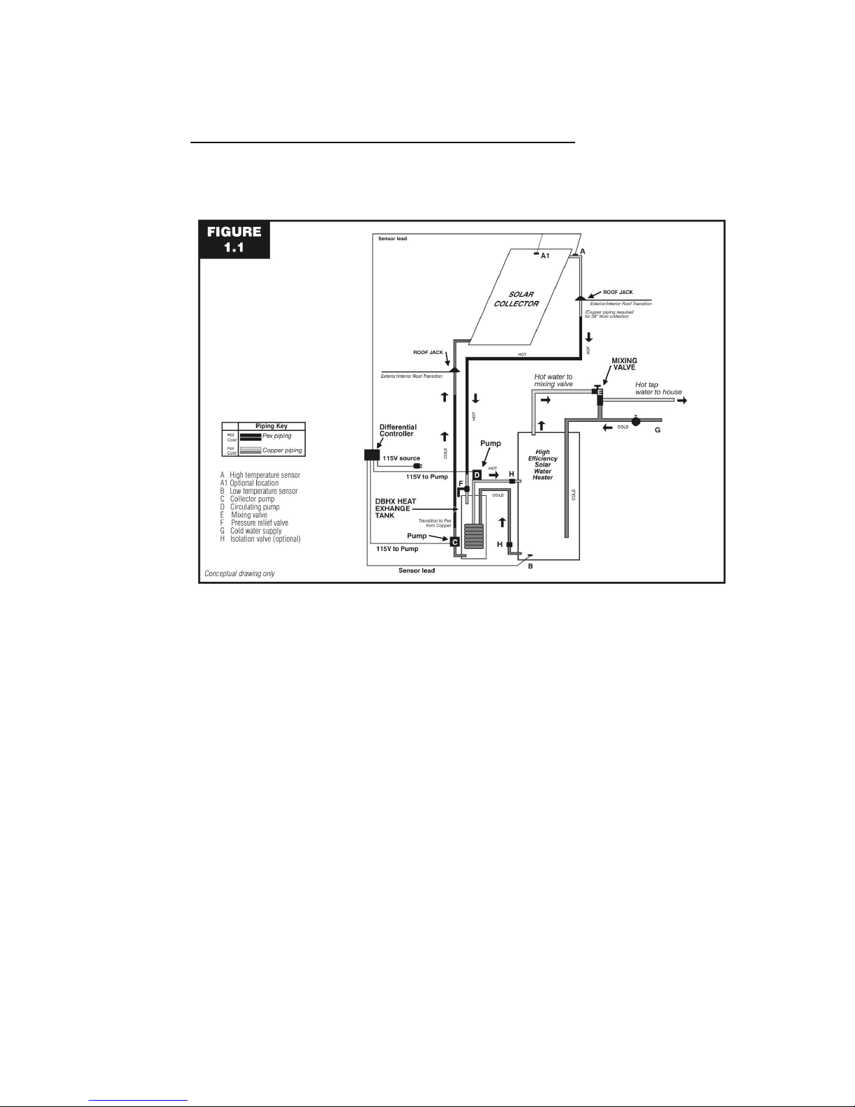
A diagram of a typical Drainback system is shown in Figure 1.1. A detailed list of Integrated
Solar’s supplied components and typical installer supplied components is provided in the
related sections of this document.
Collector circuit can be all ¾” copper tubing; if using PEX use only where shown in diagram.
Drainback System Conceptual Drawing Only
Figure 1.1
SRCC Disclaimer Statement
The solar energy system described by this manual, when properly installed and maintained,
meets the minimum standards established by the SRCC. This certification does not imply
endorsement or warranty of this product by SRCC.

4
OPERATION OF A DRAINBACK SYSTEM
The operation of a Drainback System is simple. Whenever the collector sensor reaches a
temperature 16"! to 24º F higher than the water at the bottom of the storage tank, the control
turns on the pumps. The first pump circulates the water stored in the drainback (DBHX)
storage tank through the solar collector. The water increases in temperature and is
returned to the drainback storage tank, bathing the copper coil heat exchanger in solar
heated water. The second pump circulates water from the storage tank through the copper
coil heat exchanger which transfers the heat from the collector to the storage tank. This
process continues until the collector temperature sensor is within 4º F of the storage tank
temperature sensor, or the storage tank reaches the pre-set high temperature limit, at which
time, the control unit turns the pumps off. The water in the collector loop then drains back
into the insulated DBHX tank where it remains until the collector temperature again reaches
16" to 24º F higher than the storage tank.
Freeze protection is automatic. When the control has turned the pumps off, the water in the
collector loop drains back into the DBHX storage tank. If freezing conditions occur, there is
no water in the collectors or piping to freeze and, therefore, no damage occurs.
Overheating and stagnation of the collector fluid is also automatically avoided, because the
water in the collector loop also drains back into the DBHX storage tank when the hot water
storage tank is fully heated
The primary advantage of the drainback system is that it is fail safe and can be used
anywhere. Loss of power does not disable the freeze protection, nor does any other
probable malfunction.
The key to the installation of a drainback system is to provide the proper pitch in both the
supply and return lines that connect the collector array and the DBHX reservoir tank. The
water will drain back through the pump, but to do so, air must go up the return line. Proper
sloping in all lines and the collector array, with the avoidance of water traps in the supply
line, are required to provide the drainback feature.

5
GENERAL CONSIDERATIONS
All installations must conform to local building code requirements especially for penetrating
structural members and fire-rated assemblies.
The design and installation of the system must not impair emergency movement of the
building occupants.
Do not install the collectors on a roof which already needs repairs. Keep a safe distance
from roof vents, chimneys, skylights, etc.. Take special precautions to prevent damage to
tile, shake and slate roofs.
Be sure the collector(s) are not shaded by external obstructions more than the specified
period allowed in the site design
The location, orientation, and position of the collector(s) relative to nearby objects and
surfaces shall be such that water run-off from the collector surface is not impeded. In
climates where snow may collect on the roof, excessive build-up of snow on lower portions
of the collector glazing shall not be permitted to occur. Collectors should be mounted as
close to the peak as practical on smooth roof surfaces like metal roofs and as close to the
lower edge as practical on rougher roof surfaces like asphalt shingles.
Penetrations of the building through which piping or wiring is passed shall not reduce or
impair the function of the enclosure. Structural components penetrated by solar system
components must meet applicable codes. Penetrations through fire-rated assemblies shall
not reduce the building’s fire resistance required by local codes, ordinances, and applicable
standards. Penetrations through wall or other surfaces shall not allow intrusion by insects
and/or vermin. Required roof penetrations shall be made in accordance with applicable
codes and also by practices recommended by the National Roofing Contractors Association.
Be sure any caulking and/or sealant is recommended for use on the surface(s) to which it is
applied.
Building materials adjacent to solar components should not be exposed to elevated
temperatures. Insulation in the sides and back of the collectors protect adjacent materials
from heat produced by the collector, pipe insulation must be installed to protect materials
from the heat of the collector loop piping. Insulation around the drainback tank and pipe
insulation serve to protect adjacent materials from the heat of the solar heated water. Be
sure to position the drainback module so that the pumps are not too close to walls or other
building materials, and so that the pumps are isolated from public traffic areas.
Filled Weights of Integrated Solar components
AS406C Collector 89 lbs
AS406C Collector 92 lbs
AS408P Collector 120 lbs.
AS408C Collector 121 lbs.
AS410P Collector 146 lbs.
AS410C Collector 151 lbs.
AS412P Collector 174 lbs.
AS412C Collector 179 lbs.
DBHX08 Drainback Module 117 lbs.
DBHX12 Drainback Module 164 lbs.
Temperature and Pressure Ratings of Integrated Solar components
All Collectors Maximum Operating Temperature 230" F.
Maximum Operating Pressure 30 PSI (in drainback loop)
Test Pressure 150 PSI
Drainback Modules Maximum Operating Temperature 230" F.
Maximum Operating Pressure 30 PSI (in drainback loop)
Maximum Operating Pressure 125 PSI (in Heat Exchanger loop)

6
SOLAR COLLECTOR INSTALLATION
Locate all collectors for accessibility and check the proposed roof area for compatibility.
Collectors must be located for a southerly orientation. The best location for the solar
collectors is one that provides a day-long shadow-free view of the southern sky.
Determine which manifold ends of the collector or array are to be used for the inlet and
outlet connections; the inlet at the bottom and the outlet at the top. The inlet and outlet must
be at diagonally opposite corners of the collector or array, to insure balanced flow. The
collector outlet side should be the side closest to the tank to minimize the return pipe length.
Consider the best access to the roof and internal access for attic work. Plan routes to be
used and prepare the clearances. Plan the piping runs for the least number of bends and
fittings while maintaining a minimum 1/4" per foot slope in horizontal runs.
Collector Sizing and Location
The Architectural Series collector array is typically made up of one or two collector panels
plumbed together. It is possible to plumb up to a maximum of five collectors together for a
residential Domestic Hot Water (DHW) application. It is recommended that the array be
mounted with the waterways in the vertical position (up the slope of the roof) in all cases.
Collectors mounted horizontally may not drain properly.
Select the collector array location and determine the inlet roof penetration. Locate the rafters
to which the array will be mounted and mark with a chalk line.
From the inlet pipe location, strike a horizontal line a minimum of 10 feet. Make certain there
are no dips or sags in the roof which may prevent the collector from draining. To insure
complete drainage for the solar energy system, the vertical collector array must be installed
with a minimum vertical drop towards the inlet of 1/4" per foot of collector header. Lay out
the collectors at the proposed location and place a 2 foot (min.) level on the collector near
one edge of the glazing and parallel with the ends. Orient the collector array so that the
bubble indicates the proper slope. Make certain there is no trap in the collector supply pipe
from the roof jack to the collector.

7
Mounting the collectors
Collectors can be mounted either parallel to a pitched roof surface, or, using a Panel Tilt Kit,
on a flat roof or on a pitched roof at a steeper angle than the roof slope. Any alternate
mounting method must be capable of maintaining tilt and azimuth to design conditions.
To mount collectors parallel to a pitched roof, use kit #ASZ1 or #AS1 for a single collector,
Kit #ASZ2 or #AS2 for 2 collectors side by side, or Kit #ASZ3 or #AS3 for 3 collectors side
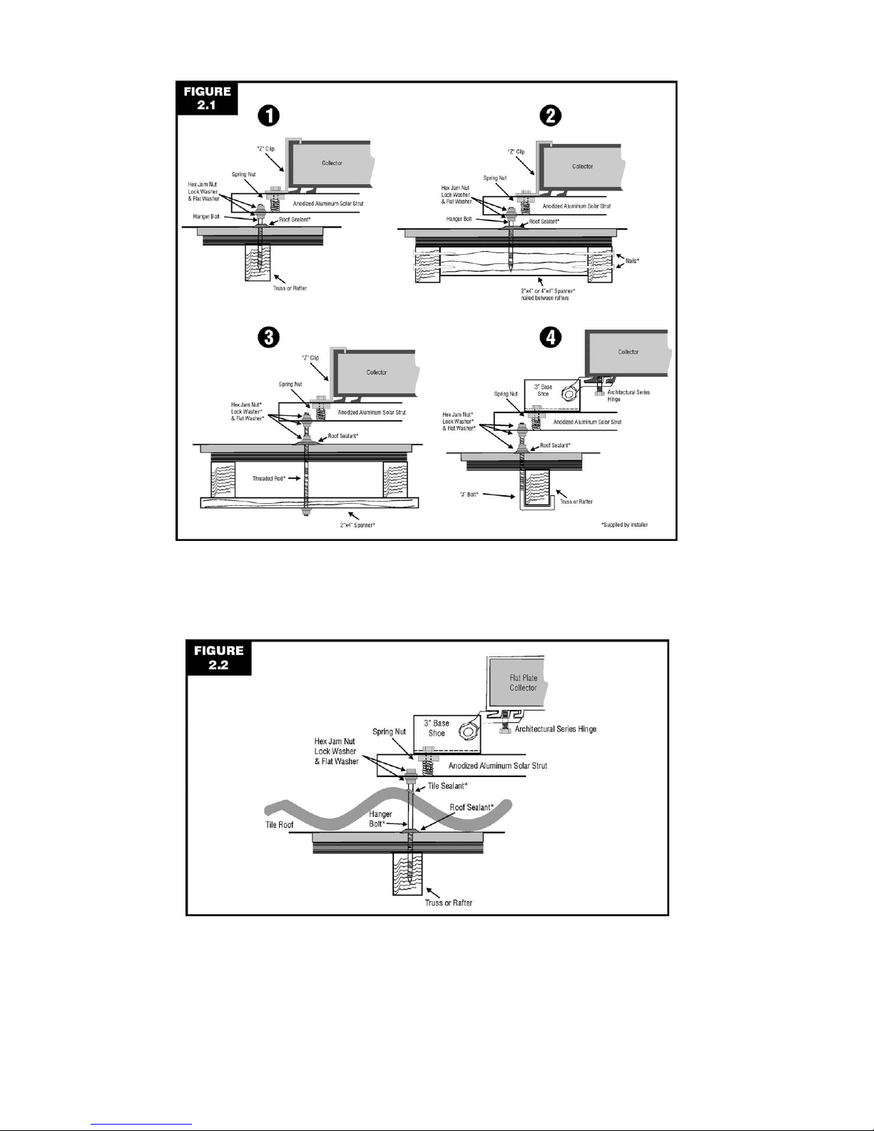
by side. Figure 2.1 shows several acceptable methods for attaching the Solar Strut to the
roof structure; local codes may dictate which method to use. CAUTION: NEVER LAG INTO
THE ROOF SHEATHING ONLY.
For barrel or “S” shaped concrete tiles, remove one tile at each penetration point and attach
a hanger bolt, threaded rod or “J” hook as shown in Figure 2.1. Use a long enough fastener
so that it extends above the top (“peak”) of the tile. Drill a hole in the tile so the fastener can
extend up through the tile when it is replaced. The strut should be above, not touching, the
top of the tile. See Figure 2.2. Although the tile is not the waterproof portion of the roof, it’s
still a good idea to seal where the fastener extends through the tile with an appropriate
sealer.
For metal roofs, use fasteners recommended by the roof manufacturer to attach the Solar
Strut.
To mount collectors using the Architectural Series Tilt Kit, first determine the length of the
riser needed to achieve the desired angle for the installation. Use one Panel Tilt Kit per
collector. Use Kit #ASTKXX5 (where “XX” is the riser length) if you wish to attach the 5”
base shoes directly to the roof as shown on the left hand side of Figure 2.3. Use Kit
#ASTKXX3 if you wish to attach the 3” shoes to Solar Strut as shown on the right side of
Figure 2.2 (for multiple collectors, the Solar Strut method is usually easier). Attach the 5”
shoes or the Solar Strut to the roof in one of the ways shown in Figure 2.1. CAUTION:
NEVER LAG INTO THE ROOF SHEATHING ONLY.
All collector installations must allow for a 2" minimum clearance between the back of the
collector and the roofing material.
8
Figure 2.1
Methods of attaching to the roof structure
Figure 2.2
Mounting above concrete tile
 Loading...