

Page 1
@@
PXOO7
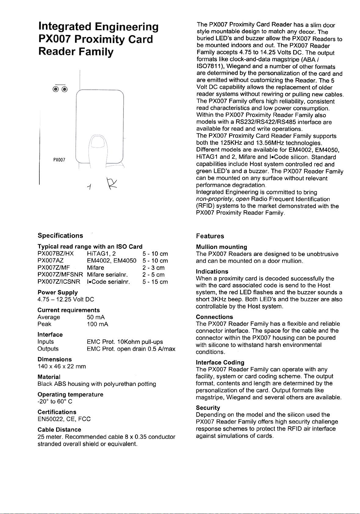
The PXOO7 Proximity Card Reader has a slim door
style mountable design to match any decor. The
buried LED's and buzzer allow the PXOO7 Readers to
be mounted indoors and out. The PXOO7 Reader
Family accepts 4.75 to 14.25 Volts DC. The output
formats like clock-and-data magstripe (ABA /
ISO7811 ), Wiegand and a number of other formats
are determined by the personalization of the card and
are emitted without customizing the Reader. The 5
Volt DC capability allows the replacement of older
reader systems without rewiring or pulling new cables.
The PXOO7 Family offers high reliability, consistent
read characteristics and low power consumption.
Within the PXOO7 Proximity Reader Family also
models with a RS232/RS422/RS485 interface are
available for read and write operations.
The PXOO7 Proximity Card Reader Family supports
both the 125KHz and 13.56MHz technologies.
Different models are available for EM4002, EM4050,
HiTAG1 and 2, Mifare and I.Code silicon. Standard
capabilities include Host system controlled red and
green LED's and a buzzer. The PXOO7 Reader Family
can be mounted on any surface without relevant
~1
performance degradation.
Integrated Engineering is committed to bring
non-propriety, open Radio Frequent Identification
(RFID) systems to the market demonstrated with the
PXOO7 Proximity Reader Family.
Specifications
Typical read range with an ISO Card
PXO07BZ/HX HiTAG1, 2 5- 10 cm
PXO07AZ EM4002, EM4050 5- 10 cm
PXO07Z/MF Mifare 2 -3 cm
PXO07Z/MFSNR Mifare serialnr. 2- 5 cm
PXO07Z/ICSNR I.Code serialnr. 5- 15 cm
Power Supply
4.75- 12.25 Volt DC
Current requirements
Average 50 mA
Peak 100 mA
Interface
Inputs EMC Prot. 10Kohm pull-ups
Outputs EMC Prot. open drain 0.5 A/max
Dimensions
140 x 46 x 22 mm
Material
Black ABS housing with polyurethan potting
Operating temperature
-20° to 60° C
Certifications
EN50022, CE, FCC
Cable Distance
25 meter. Recommended cable 8 x 0.35 conductor
stranded overall shield or equivalent.
Features
Mullion mounting
The PXOO7 Readers are designed to be unobtrusive
and can be mounted on a door mullion.
Indications
When a proximity card is decoded successfully the
with the card associated code is send to the Host
system, the red LED flashes and the buzzer sounds a
short 3KHz beep. Both LED's and the buzzer are also
controllable by the Host system.
Connections
The PXOO7 Reader Family has a flexible and reliable
connector interface. The space for the cable and the
connector within the PXOO7 housing can be poured
with silicone to withstand harsh environmental
conditions.
Interface Coding
The PXOO7 Reader Family can operate with any
facility, system or card coding scheme. The output
format, contents and length are determined by the
personalization of the card. Output formats like
magstripe, Wiegand and several others are available.
Security
Depending on the model and the silicon used the
PXOO7 Reader Family offers high security challenge
response schemes to protect the RFID air interface
against simulations of cards.
Page 2
Parts List
1) PXO07 Reader 4.75-12.25 VDC qty 1
2) Terminal Connector 8 pins qty 1
3) Mounting sticker qty 2
4) Installation sheet qty 1
5) K25 spacer plate (optional) qty 1
6) Cable, 8 x 0.35 conductor as required
Installation instruction
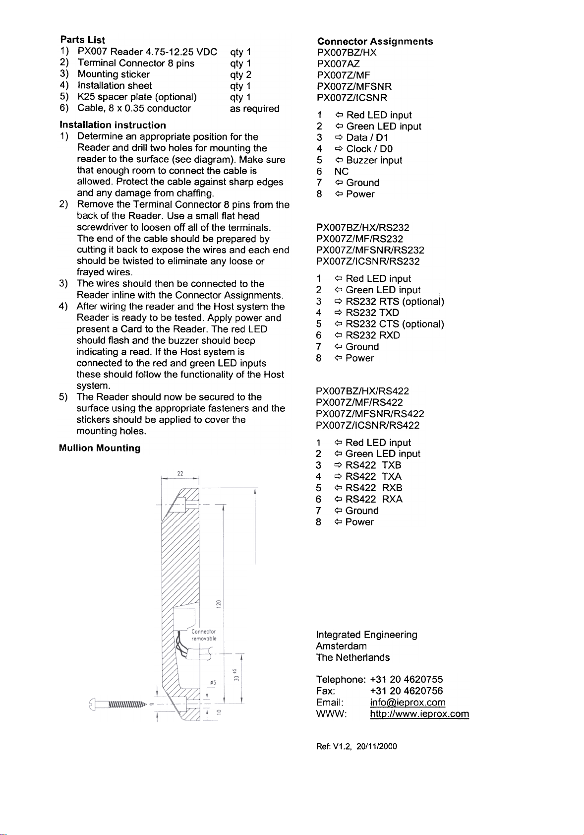
1) Determine an appropriate position for the
Reader and drill two holes for mounting the
reader to the surface (see diagram). Make sure
that enough room to connect the cable is
allowed. Protect the cable against sharp edges
and any damage from chaffing.
2) Remove the Terminal Connector 8 pins from the
back of the Reader. Use a small flat head
screwdriver to loosen off all of the terminals.
The end of the cable should be prepared by
cutting it back to expose the wires and each end
should be twisted to eliminate any loose or
frayed wires.
3) The wires should then be connected to the
Reader inline with the Connector Assignments.
4) After wiring the reader and the Host system the
Reader is ready to be tested. Apply power and
present a Card to the Reader. The red LED
should flash and the buzzer should beep
indicating a read. If the Host system is
connected to the red and green LED inputs
these should follow the functionality of the Host
system.
5) The Reader should now be secured to the
surface using the appropriate fasteners and the
stickers should be applied to cover the
mounting holes.
Mullion Mounting
Connector Assignments
PXOO7BZ/HX
PXOO7AZ
PXOO7Z/MF
PXOO7Z/MFSNR
PXOO7Z/ICSNR
1 <;::J Red LED input
2 <;::J Green LED input
3 q Data / D1
4 q Clock / DO
5 <;::J Buzzer input
6 NC
7 <;::J Ground
8 <;::JPower
PXOO7BZ/HX/RS232
PXOO7Z/MF/RS232
PXOO7Z/MFSNR/RS232
PXOO7Z/ICSN R/RS232
1 <:::J Red LED input
2 <:::J Green LED input i
3 q RS232 RTS (optiona~)
4 q RS232 TXD
5 <:::J RS232 CTS (optionaO
6 <:::J RS232 RXD
7 <:::J Ground
8 <:::J Power
PXOO7BZ/HX/RS422
PXOO7Z/MF/RS422
PXOO7Z/MFSNR/RS422
PXOO7Z/ICSNR/RS422
1 ? Red LED input
2 ? Green LED input
3 c::> RS422 TXB
4 c::> RS422 TXA
5 ? RS422 RXB
6 ? RS422 RXA
7 ? Ground
8 ?Power
Integrated Engineering
Amsterdam
The Netherlands
Telephone: +31 204620755
Fax: +31 204620756
Email: info@ieprox.co$}
WWW: http://www.iepr~x.com
Ref: V1.2, 20/11/2000
 Loading...