

Integrated Design Ltd Fastlane Installation Manual

Fastlane
®
Remote Control
Setting new standards in entrance control
Fastlane® is a registered trademark of Integrated Design Ltd 1995
Confidential
ISSUE DATE CHANGE REF
A4 06-2008 Standard Text Formatting, includes Illustrations/Photos CN1297
A5 10-2008 Made the manual more generic for the entire Fastlane range CN1358
A6 08/04/10 Update Contact Details and Warranty CN1627
INSTALLATION
Manufactured By:
Integrated Design Ltd, Feltham Point, Browells Lane,
Feltham, Middlesex, TW13 7EQ, United Kingdom
Tel: (+44) (0)208 890 5550
Fax: (+44) (0)208 890 2444
E-mail: info@idl.co.uk
Web: www.fastlane-turnstiles.com

Fastlane® Remote Control INSTALLATION MANUAL
Confidential
Page 2 of 13 Issue A6 April 2010 © Integrated Design Ltd
Confidential
Contents
Introduction.......................................................................................................... 3
Installation Procedure .......................................................................................... 4
Remote Control Wiring Connections .................................................................... 5
Alarm Indication .............................................................................................. 5
Visitor Entry/Exit ............................................................................................. 6
Key Switch ...................................................................................................... 6
Power ............................................................................................................. 7
Operation .......................................................................................................... 10
Enter Button (Timed Entry)............................................................................ 10
Exit Button (Timed Exit) ................................................................................ 10
Key Switch (3-way) ....................................................................................... 10
Alarm Indicator ............................................................................................. 10
Commissioning .................................................................................................. 11
Precautions .................................................................................................. 11
Preparation ................................................................................................... 11
Procedure ..................................................................................................... 11
Technical Specification ...................................................................................... 12
Warranty ............................................................................................................ 13
Technical Support .............................................................................................. 13
Important Notice ................................................................................................ 13
Fastlane® Remote Control INSTALLATION MANUAL
Confidential
© Integrated Design Ltd Issue A6 April 2010 Page 3 of 13
Confidential
Introduction
The aim of this manual is to provide sufficient information for suitably qualified personnel to
install and commission one or more of Integrated Design’s Remote Control Panels.
The Remote Control is designed for use only with the IDL range of Fastlane® products.
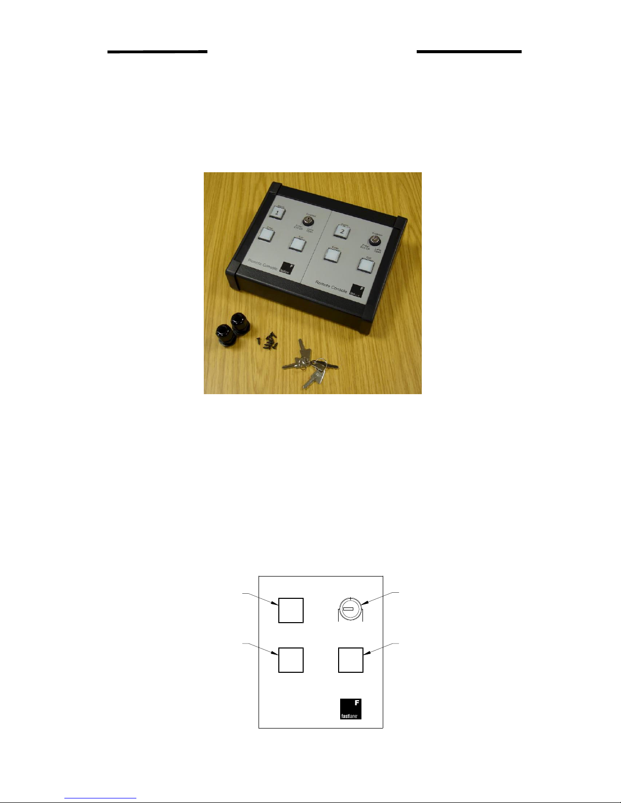
Figure 1 - Remote Control (example of 2-lane enclosure)
It is a small desktop console that provides the following functions:
• Latched Alarm Indication
• Visitor Entry Pushbutton
• Visitor Exit Pushbutton
• A Key Switch that can be configured as required
The Key Switch is typically used to disable the visitor pushbuttons, or open the lanes in
an emergency.
The Entry/Exit pushbuttons allow Visitor Access for entering or exiting the lanes. These buttons
only need to be pushed once, but firmly and for 1 second. You do not need to keep them
depressed; the Fastlane® will monitor the passage of multiple visitors, providing they follow
close behind each other (less than 3-second gap).
Figure 2 - Remote Control Panel Details
Alarm
Enter Exit
Enabled
LaneEnter/
Exit Off
Remote Console
Open
Key Switch
Visitor Exit
Visitor Enter
Alarm Indicator
Fastlane® Remote Control INSTALLATION MANUAL
Confidential
Page 4 of 13 Issue A6 April 2010 © Integrated Design Ltd
Confidential
Installation Procedure
Remove the Remote Control from the packing. During transit, the plastic sides are not fixed
and may be pulled off. The fixing screws and keys are located inside the metal casing, under
the PCBs.
Cable access into the Remote Control is at the discretion of the installer. A hole will need to be
drilled to allow the supplied cable gland(s) to be fitted; this hole can be on the rear or underside
as required. Where possible the cable should run along the bottom, inside the enclosure to the
terminals. Always leave plenty of cable spare; to allow for access later during maintenance
visits.
Never drill the cable-access holes with the circuit boards fitted. To remove the panel(s) with the
circuit board attached, slide it sideways out of the metal casing.
Select the desired location for the console, and plan the cable route. Familiarise yourself with
the wiring requirements before laying any cables.
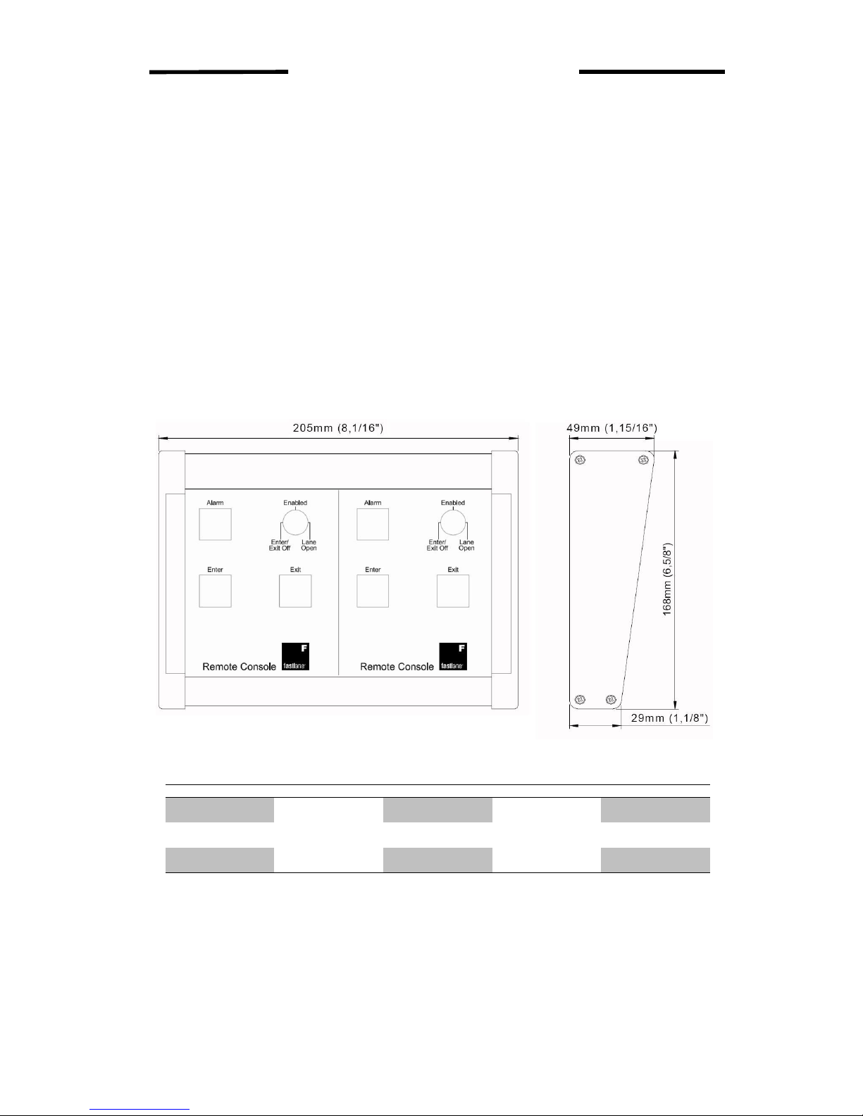
Figure 3 - Enclosure Dimensions
The Remote Control is available as 2-lane, 3-lane and 4-lane enclosures.
Enclosure Depth (mm) Width (mm) Depth (inches) Width (inches)
2-lane
168mm
205mm
6 5/8 “
8 1/16”
3-lane 304.5mm 12”
4-lane 404mm 15 7/8”
For installations with more than 4 lanes, a series of enclosures would need to be used.
 Loading...