

A 5V DC adapter is provided
(model PS-1512) with a 4.0 x 1.7
barrel connector (EIAJ 2 size). The
adapter is worldwide AC voltage
input with North American prongs
and is ultra mini in size.
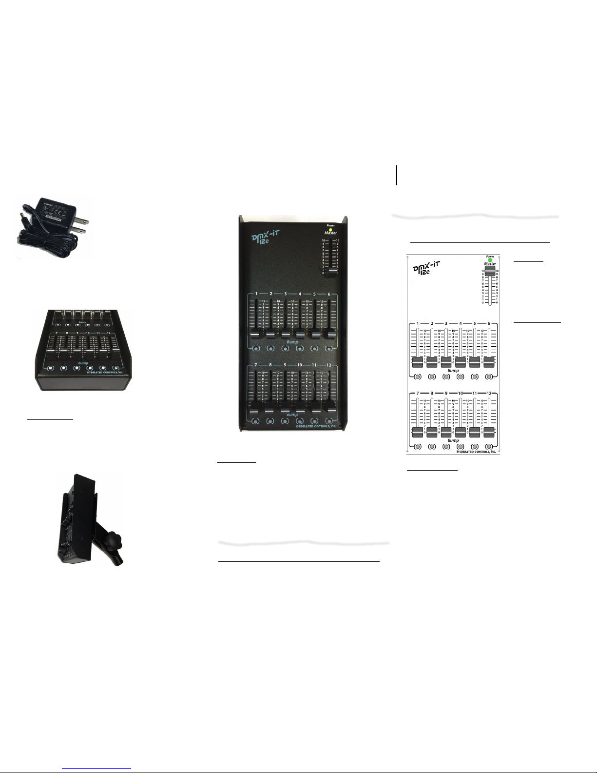
Ultra compact 12 channel DMX controller.
Rugged, lightweight with integral protective sidewall barriers.
7.2 VESA mount
On the bottom surface 4 threaded nuts are provided which
conform to the VESA mounting standard: 75mm square pattern of
four M4 threads (Metric screw size M4) typically supplied with
VESA mounts such as Stellar Labs 35-4310 Microphone Stand
VESA mounting adapter shown here.
8. Dimensions
W, H, D Front / Rear: 3.75”, 7.8”, 1.6 / 2.3”
(10cm, 120cm, 4 / 5.8cm)
Weight 1.1lbs (0.5kg), in carton 1.6lbs (0.7kg), shipping wt
2.2lbs (1kg)
Firmware version is indicated by a label on the bottom.
Model Number: 750-0814 Model Name: DMX-iT 512e
User Guide v1.32
Integrated Controls, Inc.
San Francisco, CA
www.dmxit.com
sales@dmxit.com
Integrated Controls,
Inc
.
DMX-iT 12e User Guide
1. Master
The Master fader
is a Grand Master
which acts as a final
Level for all output
levels of all functions.
2. Bump buttons
Bump buttons are
below each of the
12 channel faders
Pressing a Bump
button will
immediately raise
that channel to full
level subject to the
Master.
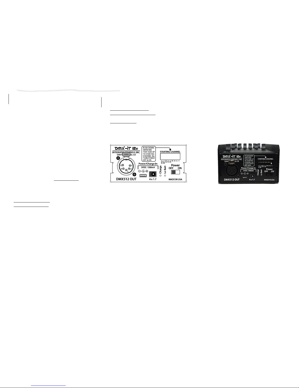
3. Basic Operation
Set the DIP switch on the reat to a starting Address
which is the same thing as your Starting Channel.
The address only read at power up so if you change the
address you must turn the power off and back on.
Push the switches down until the numbers add up to your
starting address.
A
If you change the Starting Channel you must
turn the power off and back on for the change to
take effect.
For example if you push down the switches 8 & 16
the starting address will be channel 24.
Remember that all other switches must be UP.
Many people will just set #1 to the down position
and leave the rest up for common applications
where the first light or dimmer is set to channel 1.
Fader1 will now be at Address, Fader2 will be at
Address+1, etc.
The DMX 512 universe is cleared at power up.
.
When you change the current Live Address and don’t press Change the
Red LED will blink to remind you the address is not the current live
address, when you change back to the current Live address or press
Change the Red LED will turn off. 4 Scene Memory
6. Special case addresses
6.1 Clearing the Universe
Sometimes you may want to send 0’s for the entire 512
universe.
This can be useful if dimmers retain values that you wish
they hadn’t.
Set the the Address to 999 (don’t press Change), hold Delete for 3
seconds, LED blinks, release. All 512 channels were sent 0 levels, the
scenes defaulted to off. Set the pushwheel back to your Live Address. As
of v1.31 holding down both Bumps 1&2 during power up will do the same
clearing operation. (Note that a starting Live address of 500+ w/ Master
down has the same effect of clearing the universe and the universe is also
cleared at power up)
a
the DMX 512 universe is also cleared at power up
(as of v1.32).
7. Other Features and notes
7.1 Battery and power operations
Professional 5pin XLR
1 Ground, 2 Data –, 3 Data+, 4, 5 No connect
The internal rechargeable battery runs about 2 days with a full
charge while operating continuously.
LED indication is provided on the rear panel for Charge
Status & Low Batt.
The Charge light will turn off when fully charged.
The Low Batt light indicates you should charge or plug in a
backup source if no time to recharge.
A MICRO B USB power input is also provided, external portable
battery pack “chargers” as used for smartphones or a laptop may
also be used as a power source and as a charging source for the
internal battery.
So in a pinch with a discharged internal battery and no handy AC
around you can be instantly running by attaching here (no USB
cables are supplied).
Full charge time is few hours, useful charge can be had in tens
of minutes (it will charge slightly faster with the unit OFF).
The adapter will simultaneously operate the unit and charge the
battery.
 Loading...