


DVD AUDIO/VIDEO Player
RDV-1
Instruction Manual
Before Using Your DVD Player 2
Getting Started 8
Basic Playback 22
Thank you for purchasing the Integra
RESEARCH DVD AUDIO/VIDEO Player.
Please read this manual thoroughly before
making connections and plugging in the unit.
Following the instructions in this manual will
enable you to obtain optimum performance
and listening enjoyment from your new player.
Please retain this manual for future reference.
Advanced Playback 29
Quick Control and
Performance Options
Function Setup 46
38
RDV-1(US_E)Cover.p65 10/4/00, 17:031
Remote Controller 56
Others 61
RDV-1 US/Asia 29342995
CAUTION:
TO REDUCE THE RISK OF ELECTRIC SHOCK, DO NOT
REMOVE COVER (OR BACK). NO USER-SERVICEABLE
PARTS INSIDE. REFER SERVICING TO QUALIFIED
SERVICE PERSONNEL.
triangle, is intended to alert the user to the presence of uninsulated
“dangerous voltage” within the product’s enclosure that may be of
sufficient magnitude to constitute a risk of electric shock to persons.
The exclamation point within an equilateral triangle is intended to alert
the user to the presence of important operating and maintenance
(servicing) instructions in the literature accompanying the appliance.
Important Safeguards
1. Read Instructions – All the safety and operating instructions
should be read before the appliance is operated.
2. Retain Instructions – The safety and operating instructions
should be retained for future reference.
3. Heed Warnings – All warnings on the appliance and in the
operating instructions should be adhered to.
4. Follow Instructions – All operating and use instructions
should be followed.
5. Cleaning – Unplug the appliance from the wall outlet
before cleaning. The appliance should be cleaned only as
recommended by the manufacturer.
6. Attachments – Do not use attachments not recommended
by the appliance manufacturer as they may cause
hazards.
7. Water and Moisture – Do not use the appliance near water
–for example, near a bath tub, wash bowl, kitchen sink, or
laundry tub; in a wet basement; or near a swimming pool;
and the like.
8. Accessories – Do not place the appliance on an unstable
cart, stand, tripod, bracket, or table. The appliance may
fall, causing serious injury to a child or adult, and serious
damage to the appliance. Use only with a cart, stand,
tripod, bracket, or table recommended by the
manufacturer, or sold with the appliance. Any mounting of
the appliance should follow the manufacturer’s
instructions, and should use a mounting accessory
recommended by the manufacturer.
9. An appliance and cart
combination should be
moved with care. Quick stops,
excessive force, and uneven
surfaces may cause the
appliance and cart
combination to overturn.
10. Ventilation – Slots and openings in the cabinet are
provided for ventilation and to ensure reliable operation of
the appliance and to protect it from overheating, and
these openings must not be blocked or covered. The
openings should never be blocked by placing the
appliance on a bed, sofa, rug, or other similar surface. The
appliance should not be placed in a built-in installation
such as a bookcase or rack unless proper ventilation is
provided. There should be free space of at least 5 cm and
an opening behind the appliance.
11. Power Sources – The appliance should be operated only
from the type of power source indicated on the marking
label. If you are not sure of the type of power supply to
your home, consult your appliance dealer or local power
company.
12. Grounding or Polarization – The appliance may be
equipped with a polarized alternating current line plug (a
plug having one blade wider than the other). This plug will
fit into the power outlet only one way. This is a safety
feature. If you are unable to insert the plug fully into the
outlet, try reversing the plug. If the plug should still fail to fit,
contact your electrician to replace your obsolete outlet.
Do not defeat the safety purpose of the polarized plug.
PORTABLE CART WARNING
S3125A
2
13. Power-Cord Protection – Power-supply cords should be
routed so that they are not likely to be walked on or
pinched by items placed upon or against them, paying
particular attention to cords at plugs, convenience
receptacles, and the point where they exit from the
appliance.
14. Lightning – For added protection for the appliance during
a lightning storm, or when it is left unattended and unused
for long periods of time, unplug it from the wall outlet and
disconnect the antenna or cable system. This will prevent
damage to the appliance due to lightning and power-line
surges.
15. Overloading – Do not overload wall outlets, extension
cords, or integral convenience receptacles as this can
result in a risk of fire or electric shock.
16. Object and Liquid Entry – Never push objects of any kind
into the appliance through openings as they may touch
dangerous voltage points or short-out parts that could
result in a fire or electric shock. Never spill liquid of any kind
on the appliance.
17. Servicing – Do not attempt to service the appliance
yourself as opening or removing covers may expose you to
dangerous voltage or other hazards. Refer all servicing to
qualified service personnel.
18. Damage Requiring Service – Unplug the appliance form
the wall outlet and refer servicing to qualified service
personnel under the following conditions:
A. When the power-supply cord or plug is damaged,
B. If liquid has been spilled, or objects have fallen into the
appliance,
C. If the appliance has been exposed to rain or water,
D. If the appliance does not operate normally by following
the operating instructions. Adjust only those controls
that are covered by the operating instructions as an
improper adjustment of other controls may result in
damage and will often require extensive work by a
qualified technician to restore the appliance to its
normal operation,
E. If the appliance has been dropped or damaged in any
way, and
F. When the appliance exhibits a distinct change in
performance – this indicates a need for service.
19. Replacement Parts – When replacement parts are
required, be sure the service technician has used
replacement parts specified by the manufacturer or have
the same characteristics as the original part. Unauthorized
substitutions may result in fire, electric shock, or other
hazards.
20. Safety Check – Upon completion of any service or repairs
to the appliance, ask the service technician to perform
safety checks to determine that the appliance is in proper
operation condition.
21. Wall or Ceiling Mounting – The appliance should be
mounted to a wall or ceiling only as recommended by the
manufacturer.
22. Heat – The appliance should be situated away from heat
sources such as radiators, heat registers, stoves, or other
appliances (including amplifiers) that produce heat.
RDV-1(US_E)p02-07.p65 10/4/00, 17:032
RDV-1 US/Asia 29342995

This unit contains a semiconductor laser system and is
classified as a “CLASS 1 LASER PRODUCT”. So, to use this
model properly, read this Instruction Manual carefully. In
case of any trouble, please contact the store where you
purchased the unit. To prevent being exposed to the laser
beam, do not try to open the enclosure.
CAUTION:
VISIBLE LASER RADIATION WHEN OPEN AND INTERLOCK
FAILED OR DEFEATED. DO NOT STARE INTO BEAM.
CAUTION:
THIS PRODUCT UTILIZES A LASER. USE OF CONTROLS OR
ADJUSTMENTS OR PERFORMANCE OF PROCEDURES OTHER
THAN THOSE SPECIFIED HEREIN MAY RESULT IN HAZARDOUS
RADIATION EXPOSURE.
The label on the
right is applied on
the rear panel
except for USA and
Canadian models.
1. This unit is a CLASS 1 LASER PRODUCT and employs a
laser inside the cabinet.
2. To prevent the laser from being exposed, do not
remove the cover. Refer servicing to qualified
personnel.
“CLASS 1 LASER
PRODUCT”
For U.S. model
The laser is covered by a housing which prevents exposure
during operation or maintenance. However, this product is
classified as a Laser Product by CDRH (Center for Devices and
Radiological Health) which is a department of the Food and
Drug Administration. According to their regulations 21 CFR
section 1002.30, all manufactures who sell Laser Products must
maintain records of written communications between the
manufacturer, dealers and customers concerning radiation
safety. If you have any complaints about instructions or
explanations affecting the use of this product, please feel free
to write to the address on the back page of this manual. When
you write us, please include the model number and serial
number of your unit.
In compliance with Federal Regulations, the certification,
identification and the period of manufacture are indicated on
the rear panel.
FCC INFORMATION FOR USER
CAUTION:
The user changes or modifications not expressly approved by
the party responsible for compliance could void the user’s
authority to operate the equipment.
NOTE:
This equipment has been tested and found to comply with the
limits for a Class B digital device, pursuant to Part 15 of the FCC
Rules. These limits are designed to provide reasonable
protection against harmful interference in a residential
installation. This equipment generates, uses and can radiate
radio frequency energy and, if not installed and used in
accordance with the instructions, may cause harmful
interference to radio communications. However, there is no
guarantee that interference will not occur in a particular
installation. If this equipment does cause harmful interference
to radio or television reception, which can be determined by
turning the equipment off and on, the user is encouraged to
try to correct the interference by one or more of the following
measures:
• Reorient or relocate the receiving antenna.
• Increase the separation between the equipment and
receiver.
• Connect the equipment into an outlet on a circuit different
from that to which the receiver is connected.
• Consult the dealer or an experienced radio/TV technician
for help.
For Canadian model
This class B digital apparatus complies with Canadian ICES-
003.
For models having a power cord with a polarized plug:
CAUTION: TO PREVENT ELECTRIC SHOCK, MATCH WIDE BLADE
OF PLUG TO WIDE SLOT, FULLY INSERT.
Modele pour les Canadien
Cet appareil numérique de la classe B est conforme à la
norme NMB-003 du Canada.
Sur les modeles dont la fiche est polarisee:
ATTENTION: POUR EVITER LES CHOCS ELECTRIQUES, INTRODUIRE
LA LAME LA PLUS LARGE DE LA FICHE DANS LA BORNE
CORRESPONDANTE DE LA PRISE ET POUSSER JUSQU’AU FOND.
RDV-1(US_E)p02-07.p65 10/4/00, 17:033
3
RDV-1 US/Asia 29342995

1. Regional Restriction Codes (Region Number)
Regional restriction codes are built into DVD Players and
DVD-Video media for each sales region. If the regional
code of the DVD Player does not match one of the
regional codes on the DVD-Video, playback is not possible.
The regional number can be found on the rear panel of
the DVD Player. (e.g. 1 for Region 1)
2. About This Manual
This manual explains the basic procedures for operating
the DVD Player. Some DVD-Video and DVD-Audio discs do
not support the full potential of the DVD technology. Your
DVD Player may therefore not respond to all operating
commands. Refer to instruction notes on discs.
” mark may appear on the TV screen during
A “
operation. It means that the operation is not permitted by
the DVD Player or the disc.
3. Warranty Claim
You can find the serial number on the rear panel of the
unit. In case of warranty claim, please report this number.
4. Recording Copyright
Recording of copyrighted material for other than personal
use is illegal without permission of the copyright holder.
5. Power
WARNING
BEFORE PLUGGING IN THE UNIT FOR THE FIRST TIME, READ THE
FOLLOWING SECTION CAREFULLY.
The voltage of the available power supply differs
according to country or region. Be sure that the power
supply voltage of the area where the unit will be used
meets the required voltage (e.g., AC 120 V, 60 Hz) written
on the rear panel.
6. Do not touch the unit with wet hands
Do not handle the unit or power cord when your hands are
wet or damp. If water or any other liquid enters the case,
take the unit to an authorized service center for inspection.
7. Location of the unit
• Place the unit in a well-ventilated location.
Take special care to provide plenty of ventilation on all
sides of the unit especially when it is placed in an audio
rack. If ventilation is blocked, the unit may overheat and
malfunction.
• Do not expose the unit to direct sunlight or heating units
as the unit’s internal temperature may rise and shorten
the life of the pickup.
• Avoid damp and dusty places and places directly
affected by vibrations from the speakers. In particular,
avoid placing the unit on or above one of the speakers.
• Be sure the unit is placed in a horizontal position. Never
place it on its side or on a slanted surface as it may
malfunction.
• When you place the unit near a TV, radio, or VCR, the
playback picture may become poor and the sound may
be distorted. In this case, place the unit away from the TV,
radio, or VCR.
8. Care
From time to time you should wipe the front and rear
panels and the cabinet with a soft cloth. For heavier dirt,
dampen a soft cloth in a weak solution of mild detergent
and water, wring it out dry, and wipe off the dirt. Following
this, dry immediately with a clean cloth.
Do not use rough material, thinners, alcohol or other
chemical solvents or cloths since these could damage the
finish or remove the panel lettering.
9. Notes on Handling
• When shipping the unit, use the original shipping carton
and packing materials. For maximum protection, repack
the unit as it was originally packed at the factory.
• Do not use volatile liquids, such as insect spray, near the
unit. Do not leave rubber or plastic products in contact
with the unit for a long time. They will leave marks on the
finish.
• The top and rear panels of the unit
after a long period of use. This is not a malfunction.
• When the unit is not in use, be sure to remove the disc
and turn off the power.
• If you do not use the unit for a long period, the unit may
not function properly in the future. Turn on and use the
unit occasionally.
may become warm
10. To Obtain a Clear Picture
The unit is a high technology, precision device. If the optical
pick-up lens and disc drive parts are dirty or worn down,
the picture quality becomes poor. To obtain a clear
picture, we recommend regular inspection and
maintenance (cleaning or parts replacement) every 1,000
hours of use depending on the operating environment. For
details, contact your nearest dealer.
11. Notes on Moisture Condensation
Moisture condensation damages the unit.
Please read the following carefully.
• What is moisture condensation?
Moisture condensation occurs, for example, when you
pour a cold drink into a glass on a warm day. Drops of
water form on the outside of the glass. In the same way,
moisture may condense on the optical pick-up lens
inside the unit, one of the most crucial internal parts of
the unit.
• Moisture condensation occurs in the following cases.
– When you bring the unit directly from a cold place to
a warm place.
– When you use the unit in a room where you just turned
on the heater, or a place where the cold wind from
the air conditioner directly hits the unit.
– In summer, when you use the unit in a hot and humid
place just after you move the unit from an air
conditioned room.
– When you use the unit in a humid place.
• Do not use the unit when moisture condensation may
occur.
If you use the unit in such a situation, it may damage
discs and internal parts. Remove the disc, connect the
power cord of the unit to the wall outlet, turn on the unit,
and leave it for two or three hours. After a few hours, the
unit will have warmed up and evaporated any moisture.
Keep the unit connected to the wall outlet and moisture
condensation will seldom occur.
4
RDV-1(US_E)p02-07.p65 10/4/00, 17:034

Important Safeguards/Precautions/Table of Contents/Notes on Discs ...2 - 6
Getting Started
Features/Supplied Accessories .......................................................................... 8
Preparing the Remote Controller ...................................................................... 9
Making Connections ......................................................................................... 10
Using the D/A Converter to Listen to Other Components ............................14
Control Position and Names .............................................................................16
Connecting the Power/Turning on the DVD Player ....................................... 19
Setting up the DVD Player for Optimal Performance .................................... 20
Basic Playback
Playing DVD-Video/Audio, Video CD, and CD .............................................. 22
Locating a Specific Title/Group/Chapter/Track/Location ........................... 26
Advanced Playback
Playing Repeatedly ...........................................................................................29
Playing in a Favorite Order ...............................................................................30
Playing in Random Order ................................................................................. 31
Zooming a Picture ............................................................................................. 32
Improving Picture Quality ................................................................................. 33
Selecting the Camera Angle ........................................................................... 34
Selecting the Subtitle Language/Turning On/Off Subtitles ........................... 35
Selecting the Audio Language........................................................................ 36
Output Sound Conversion Table ...................................................................... 37
Quick Control and Performance Options
Using the Graphic Remote Control - V.REMOTE ............................................. 38
Selecting the Playback Function - QUICK ...................................................... 39
Accessing Playback Features - NAVI ............................................................... 40
Selecting Progressive Video Output ................................................................ 44
Turning Off the Video Signal Output ................................................................ 45
Function Setup
Customizing the Function Settings ................................................................... 46
Remote Controller
Using the Remote Controller ............................................................................ 56
Programming the Commands of Other Remote Controller Units
into the Remote Controller ........................................................................ 58
Others
Troubleshooting.................................................................................................. 61
Specifications ..................................................................................................... 63
Table of Languages ................................................................ back cover page
RDV-1(US_E)p02-07.p65 10/4/00, 17:035
5
This section shows you how to handle, clean, and store discs.
Playable Discs
This DVD Player can playback the following discs.
Disc mark
DVD-
Video
DVD-
Audio
Video
CD
CD
• CD-R and CD-RW discs recorded by CD-DA method
can also be played. Some CD-R/RW discs may be
incompatible.
• You cannot playback discs other than those listed
above.
• You cannot play discs such as CD-ROM, DVD-RAM,
DVD-RW, etc., even if the marks in the above table are
labeled on those discs.
• This DVD Player uses the PAL*/NTSC color system, and
cannot playback video media recorded in any other
color system (SECAM, etc.).
• Avoid using heart-shaped or octagonal discs. Playing
irregularly shaped discs may damage the internal
mechanism of the DVD Player.
Contents
Audio
+
Video
(moving
pictures)
Audio
Audio +
Video
(moving
pictures)
Audio
Discs with shapes such as
these cannot be played.
Disc size
12 cm
8 cm
12 cm
8 cm
12 cm
8 cm
12 cm
8 cm (CD
single)
Handling Discs
• Do not touch the playback side of the disc.
Playback side
• Do not attach paper or tape to discs.
Cleaning Discs
• Fingerprints and dust on the disc cause picture and
sound deterioration. Wipe the disc from the center
outwards with a soft cloth. Always keep the disc clean.
• If you cannot wipe off the dust with a soft cloth, wipe
the disc lightly with a slightly moistened soft cloth and
finish with a dry cloth.
• Do not use any type of solvent such as thinner, benzine,
commercially available cleaners or antistatic spray for
vinyl LPs. It may damage the disc.
Storing Discs
• Do not store discs in a place subject to direct sunlight
or near heat sources.
• Do not store discs in places subject to moisture and
dust such as a bathroom or near a humidifier.
• Store discs vertically in a case. Stacking or placing
objects on discs outside of their case may cause
warping.
• Do not use discs that have residue from adhesive tape,
rental discs that have peeling labels, or discs that have
custom labels or stickers. Otherwise, you may not be
able to eject the discs or the DVD Player may become
inoperative.
* Not applicable for USA and Canadian models
6
RDV-1(US_E)p02-07.p65 10/4/00, 17:036
About Video CDs
The Structure of the Disc Content
This DVD Player supports Video CDs equipped with the
PBC (Version 2.0) function. (PBC is the abbreviation of
Playback Control.) You can enjoy two playback
variations depending on the type of disc.
• Video CD not equipped with PBC function (Version 1.1)
Sound and movies can be played on this DVD Player in
the same way as a CD.
• Video CD equipped with PBC function (Version 2.0)
In addition to operation of the Video CD not equipped
with the PBC function, you can enjoy playback with
interactive software and search function using the
menu displayed on the TV screen (Menu Playback).
Some of the functions described in this Instruction
Manual may not work with some discs.
Notes on Copyright
It is forbidden by law to copy, broadcast, show, broadcast
on cable, play in public, and rent copyrighted material
without permission.
The video recorded on DVD-Video is copy protected,
and any recordings made from these discs will be
distorted.
This product incorporates copyright protection
technology that is protected by method claims of
certain U.S. patents and other intellectual property rights
owned by Macrovision Corporation and other rights
owners. Use of this copyright protection technology must
be authorized by Macrovision Corporation, and is
intended for home and other limited viewing uses only
unless otherwise authorized by Macrovision Corporation.
Reverse engineering or disassembly is prohibited.
DVD-Video
Normally, the contents of DVD-Video are divided into
titles, and the titles are subdivided into chapters.
Title 1
Chapter 1
DVD-Audio
The contents of DVD-Audio are divided into groups, and
the groups are subdivided into tracks.
Track 1 Track 2
Video CD/CD
Video CD and CD are divided into tracks.
Track 1 Track 2
Chapter 2
Group 1
Chapter 1
Track 1
Track 3
Title 2
Chapter 2
Group 2
Track 2 Track 3
Track 4 Track 5
Chapter 3
RDV-1(US_E)p02-07.p65 10/4/00, 17:037
7
Features
THX*1 Ultra Certified
Plays DVD-Audio & Video Discs, Video CDs, CD-Rs & CDs
192 kHz/24-bit Linear PCM D/A Converters
Apogee*2 Clock System for the Highest Quality Digital
Conversion
DB-25 and RCA-6ch Multichannel Outputs
Progressive Component-Video Outputs
4 Digital Outputs pass DTS®*3, Dolby®*4 Digital, MPEG* and
PCM Signals
Dolby® Digital decoder Built In
Vector Linear Conversion System
High-Quality Dual Power Supplies, Dual Toroidal
transformers.
External Digital Inputs (Optical/Coaxial)
Direct Digital Path
Full-function remote controller with “Learning” function
for control of other component
* Not applicable for USA and Canadian models
Supplied Accessories
Make sure your box contains everything listed below.
If any pieces are missing, contact your nearest Onkyo dealer.
The number of accessories is indicated in brackets [ ].
For USA and Canadian models
*1Manufactured under license from Lucasfilm Ltd.
Lucasfilm and THX are registered trademarks of
Lucasfilm Ltd.
For other models
*1Manufactured under license from Lucasfilm Ltd.
Lucasfilm and THX are trademarks of Lucasfilm Ltd.
*2Clocked by Apogee is under licence and trademark
of Apogee Electronics, Inc.
3
“DTS” and “DTS Digital Surround” are trademark of
*
Digital Theater Systems, Inc.
4
*
Manufactured under license from Dolby Laboratories.
“Dolby”, “Pro Logic” and the double-D symbol are
trademarks of Dolby Laboratories. Confidential
Unpublished Works. ©1992-1997 Dolby Laboratories, Inc.
All rights reserved.
THX Ultra
Before any home theatre component can be THX Ultra
certified, it must pass a rigorous series of quality and
performance tests. Only then can product feature the THX
Ultra logo, which is your guarantee that the Home Theatre
products you purchase will give you superb performance
for many years to come.
CV plug (1) (worldwide models only)
Remote controller (RC-439DV) [1]
Batteries (size AA/UM-3) [2]
S-video cable [1]
Power cord [1]
The power cord may
differ depending on
the region.
Audio/video connection cable [1]
DB-25 cable [1]
8
RDV-1(US_E)p08-09.p65 10/4/00, 17:038
RDV-1 US/Asia 29342995
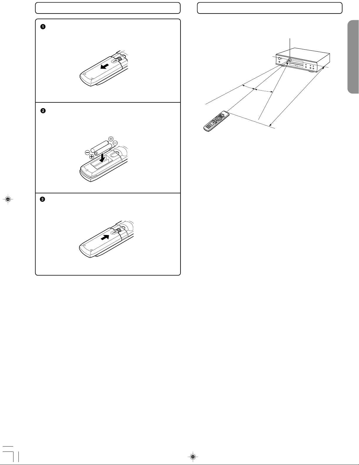
Inserting the Batteries
Using the Remote Controller
Open the battery compartment cover.
Insert the two R6 (size AA) batteries.
Be sure to match the + and – ends of the
batteries with the diagram inside the battery
compartment.
Close the battery compartment cover.
Point the remote controller toward the remote control
sensor.
Remote control sensor
30˚
30˚
About 5 m
Notes
•Place the unit away from strong light such as direct sunlight or
inverted fluorescent light which can prevent proper operation
of the remote controller.
•Using another remote controller of the same type in the same
room or using the unit near equipment which uses infrared rays
may cause operational interference.
•Do not put any object such as a book on the remote
controller. The buttons of the remote controller may be pressed
by mistake and drain the batteries.
•Make sure the audio rack doors do not have colored glass.
Placing the unit behind such doors may prevent proper
remote controller operation.
•If there is any obstacle between the remote controller and the
remote control sensor, the remote controller will not operate.
Notes
•Do not mix new batteries with old batteries or different
kinds of batteries.
•To avoid corrosion, remove the batteries if the remote
controller is not to be used for a long time.
•Remove dead batteries immediately to avoid damage
from corrosion. If the remote controller does not operate
smoothly, replace both batteries at the same time.
•The life of the batteries supplied is about six months but
this will vary depending on usage.
9
RDV-1(US_E)p08-09.p65 10/4/00, 17:039
RDV-1 US/Asia 29342995
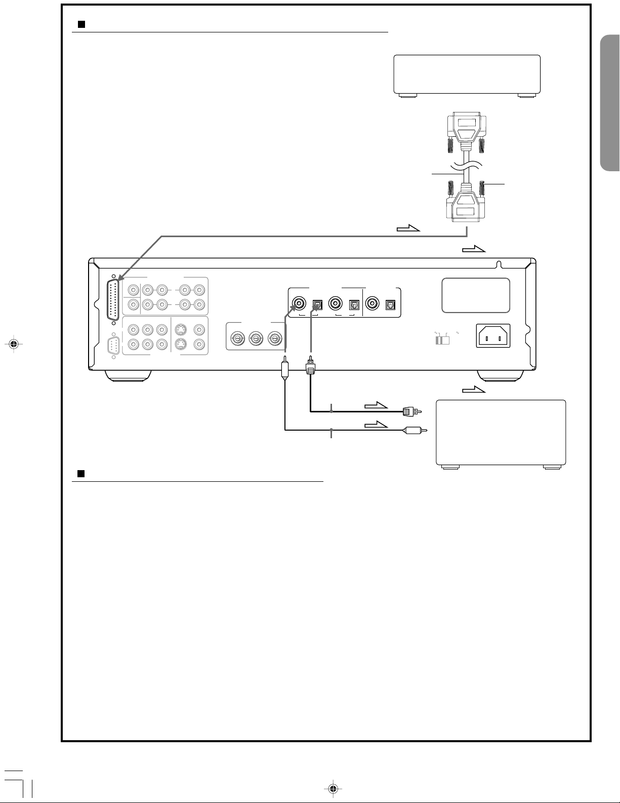
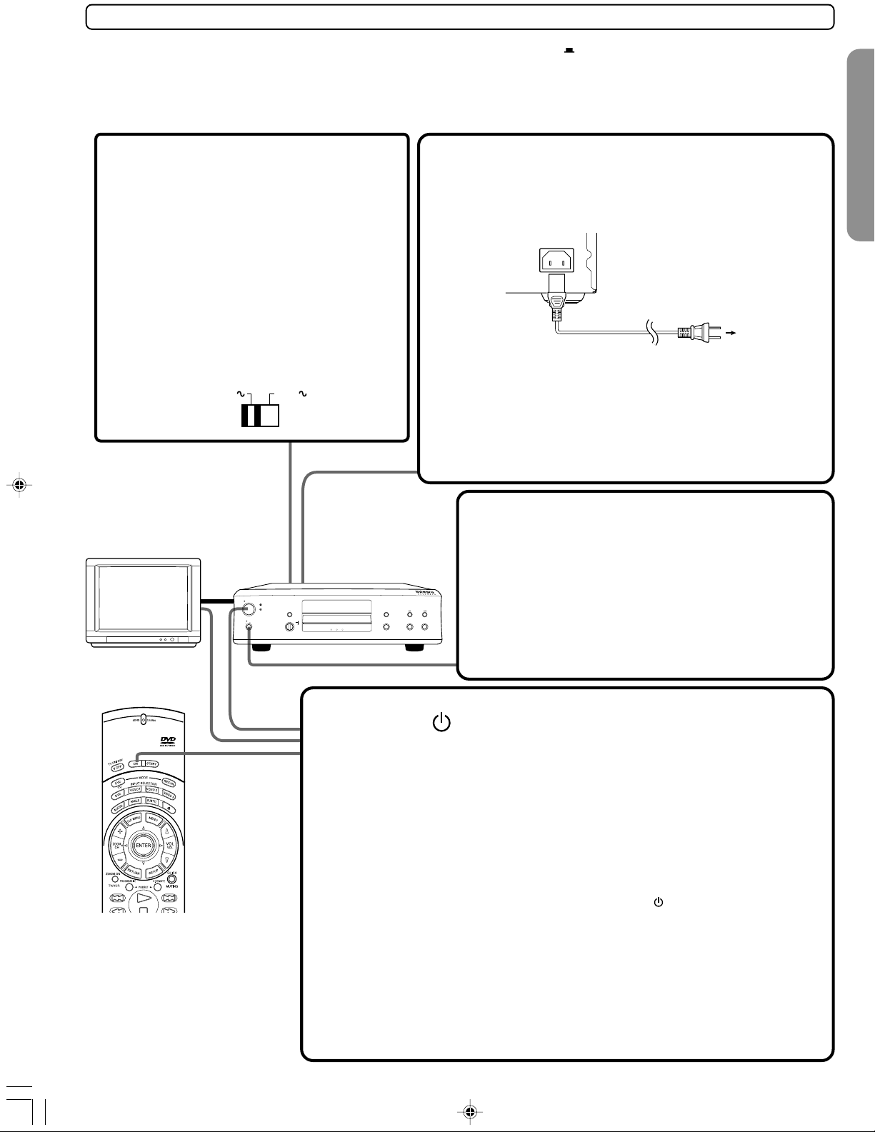
To accommodate a wide range of home entertainment systems, this player features numerous connection types for
both audio and video. Please refer to the instructions on this and the following pages to determine the best possible type
of connections for your system.
Before Connecting
•Refer to the instruction manuals supplied with any and all
components that you plan to connect the DVD Player to.
•Be sure to turn off the power of all components to be
connected and unplug them from the wall outlet before
making any connections.
•Connect the DVD Player to the TV directly. If you connect the
DVD Player to a VCR, TV/VCR combination, or video selector,
the playback picture may be distorted as DVD Video images
are copy protected.
•Please note that video connections to a TV or monitor are
necessary because some discs require on-screen menu
interaction before they can be played.
•Connect the plugs securely.
Incomplete
Inserted completely
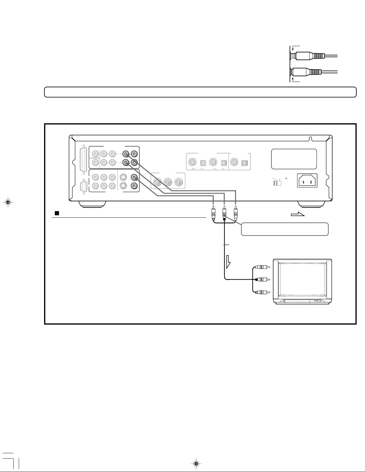
Connections to a TV
The diagram below shows how to make connections to a TV with built-in stereo speakers using the supplied audio/video
cable. After making the connections on this page, you will be able to start using the DVD Player.
ANALOG OUTPUT
RS 232 MULTI CHANNEL OUTPUT
CENTER
SUBWOOFER
CH 1
2
CH
SURR FRONT CH
COMPONENT
BPR
YP
VIDEO OUTPUT
2
1 CH
L
R
VIDEOS VIDEO
VIDEO OUTPUT
COMPONENT
Y
PBP
R
OPTICAL
COAXIAL COAXIAL
CH 1
DIGITAL INPUTDIGITAL OUTPUT
OPTICAL
COAXIAL OPTICAL
CH 2
DO NOT connect the
power cord until all
connections are
complete.
VOLTAGE SELECTOR
120 V
220 -230 V
AC INLET
Using the supplied audio/video connection cable
Using the supplied audio/video cable, make audio
connections from the ANALOG OUTPUT CH1 or CH2 L and R
jacks to the corresponding audio input jacks on the TV. In
the same manner, make video connection from the VIDEO
OUTPUT VIDEO CH1 or CH2 jack to the corresponding video
input jack on the TV.
Be sure to set Audio Out Select to “Analog 2Ch” using the
on-screen menu explained in “Customizing the Function
Settings” starting on page 46. See page 50 for direct
information.
Note
Be sure to match the colors of the plugs on the cable with the
corresponding jacks on the DVD Player and the TV: yellow for
video, red for R (right) audio and white for L (left) audio.
R (Red)
(Yellow)
L (White)
If the TV audio input is monaural, leave the
red plug disconnected.
Audio/video cable (supplied)
To audio inputs
To video input
(Yellow)
: Signal flow
L (White)
R (Red)
10
RDV-1(US_E)p10-21.p65 10/4/00, 17:0310
RDV-1 US/Asia 29342995
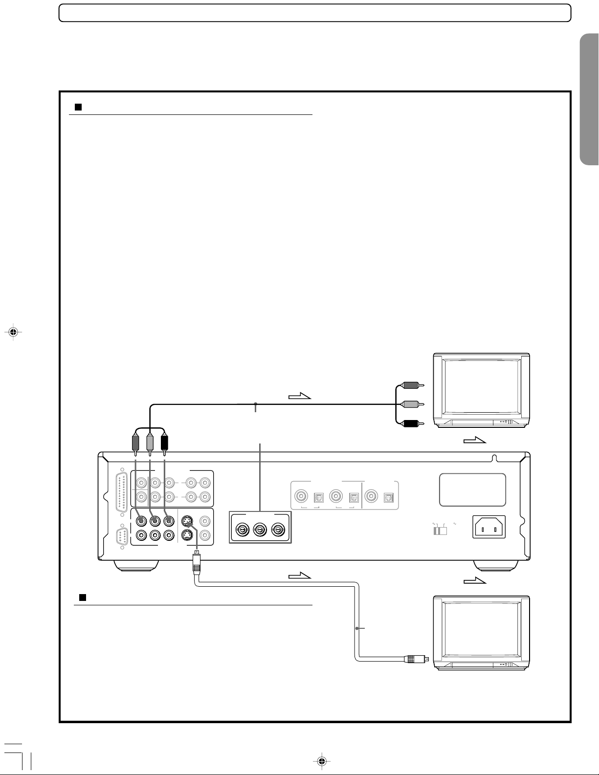
Optional Video Connections
Visible improvements in DVD-Video quality can be achieved by making either S-video or component video connections
to a TV or monitor compatible with these types of connections.
Note
When either S-video or component video connection is made, it is not necessary to make composite video connections using the
yellow cord of the audio-video cable.
Making component video connections
If the TV or monitor has component video inputs, making
this type of video connection will produce the ideal
picture quality for the presentation of DVD-Video. Using a
component video cable (sold separately), connect the
VIDEO OUTPUT COMPONENT CH1 or CH2 jacks to the
corresponding component video input jacks on the TV.
Some TVs and monitors use BNC jacks for the component
video input. When this is the case, make connections to
the VIDEO OUTPUT COMPONENT BNC jacks using a
component video cable that has BNC plugs. Actual
labels for component video inputs may vary depending
on the TV manufacturer. (e.g. Y, R-Y, B-Y or Y, C
B, CR)
In some TVs or monitors, the color levels of the playback
picture may be reduced slightly or the tint may change.
In such a case, adjust the TV or monitor for optimum
performance.
Be sure to set Audio Out Select to “Analog 2Ch” using the
on-screen menu explained in “Customizing the Function
Settings” starting on page 46. See page 50 for direct
information.
PROGRESSIVE outputs
Some TVs or monitors are equipped with component
video inputs that are capable of reproducing a
progressively scanned video signal. Connecting to these
inputs allows you to view the highest quality pictures with
less flicker.
Interlaced outputs
Some TVs or monitors are equipped with component
video inputs. Connecting to these inputs allows you to
enjoy higher quality picture playback.
In some TVs or monitors, the color levels of the playback
picture may be reduced slightly or the tint may change. In
such a case, adjust the TV or monitor for optimum
performance.
To switch the output signal (Progressive/Interlaced)
Press PROGRESSIVE on the remote control.
The output signal alternates between component
progressive and component interlaced. For details, refer to
“Selecting Progressive Video Output” on page 44.
To component video
inputs
Y
PB
Component video cable
(not supplied)
VIDEO OUTPUT COMPONENT (BNC jack)
ANALOG OUTPUT
RS 232 MULTI CHANNEL OUTPUT
CENTER
SUBWOOFER
CH 1
CH
2
YP
SURR FRONT CH
COMPONENT
B PR
VIDEO OUTPUT
L
R
1CH
VIDEOS VIDEO
2
COAXIAL COAXIAL
VIDEO OUTPUT
COMPONENT
YPBP
R
Making S-video connections
If the TV or monitor has an S-video input, making this
type of video connection will produce improved
picture quality. Using an S-video cable, connect the
VIDEO OUTPUT S VIDEO CH1 or CH2 jack to the
corresponding S-video input jack on the TV.
Be sure to set Audio Out Select to “Analog 2Ch” using
the on-screen menu explained in “Customizing the
Function Settings” starting on page 46. See page 50 for
direct information.
PR
: Signal flow
DIGITAL INPUTDIGITAL OUTPUT
OPTICAL
CH 1
OPTICAL
COAXIAL OPTICAL
CH 2
DO NOT connect the
power cord until all
connections are
complete.
VOLTAGE SELECTOR
120 V
220 -230 V
AC INLET
: Signal flow
S-video
cable
(supplied)
To S-video input
RDV-1(US_E)p10-21.p65 10/4/00, 17:0311
11
RDV-1 US/Asia 29342995
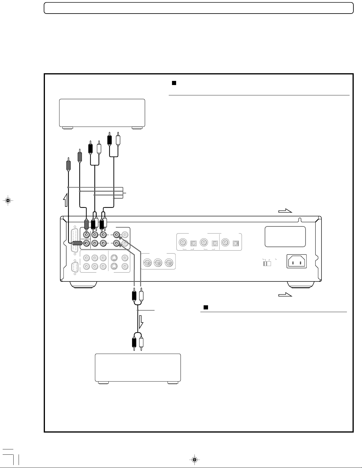
Optional Audio Connections
This DVD Player provides numerous ways to take full advantage of the digital multi channel sound recorded on DVD media.
When listening to DVD-Audio
For full enjoyment of DVD-Audio media, it is recommended to make connections to the 6-channel ANALOG OUTPUT jacks. Audio output
of DVD-Audio cannot be played back efficiently when output as a bitstream or PCM from the DIGITAL OUTPUT jacks.
Analog connections
In addition to offering two stereo outputs for connection to a stereo system, two types of multi channel analog output allow you to
make connections to an AV component that features multi channel analog input for full enjoyment of multi channel DVD-Audio discs.
Making discrete 6-channel ANALOG OUTPUT
connections
The discrete ANALOG OUTPUT jacks are intended to deliver up to 5.1
An amplifier or receiver with
six channel discrete input
FRONT R
FRONT L
SURROUND R
SURROUND L
CENTER
SUBWOOFER
To audio inputs
Audio cables
(not supplied)
channels of multi channel audio from DVD-Audio sources. Connections
can be made from the ANALOG OUTPUT FRONT, SURR (surround),
CENTER, and SUBWOOFER jacks to the corresponding input jacks on an
AV component with multi channel discrete audio input jacks.
Notes
•The audio of DVD-Audio that have been recorded in multi channel audio is
output from the 5.1channel ANALOG OUTPUT jacks regardless of the Audio
Out Select setting. In order to enjoy the audio of DVD-Audio, it is necessary to
make connections to the 5.1channel ANALOG OUTPUT jacks. Additionally,
please note that there is no audio output from the DIGITAL OUTPUT jacks.
•When a DVD-Video has been recorded in multi channel audio, the audio is
downmixed to a 2-channel stereo mix and output from the ANALOG OUTPUT
jacks (CH1, CH2, or FRONT).
•To ensure proper delivery of sound, be sure to match the names of the jacks
on the DVD Player and the component being connected to.
RS 232 MULTI CHANNEL OUTPUT
CENTER
SUBWOOFER
CH 1
2
CH
ANALOG OUTPUT
SURR FRONT CH
COMPONENT
B PR
YP
VIDEO OUTPUT
2
1 CH
L
R
VIDEOS VIDEO
R (Red)
VIDEO OUTPUT
COMPONENT
YPBP
L (White) L (White)
Audio cable
(not supplied)
R (Red)
To audio inputs
An amplifier or receiver with
stereo inputs
COAXIAL COAXIAL
R
: Signal flow
DIGITAL INPUTDIGITAL OUTPUT
OPTICAL
CH 1
OPTICAL
COAXIAL OPTICAL
CH 2
DO NOT connect the
power cord until all
connections are
complete.
VOLTAGE SELECTOR
120 V
220 -230 V
AC INLET
: Signal flow
Making stereo audio connections
Using an audio cable (sold separately), make audio
connections from the ANALOG OUTPUT CH1 or CH2 L
and R jacks to the corresponding jacks on the stereo
component.
Be sure to set Audio Out Select to “Analog 2Ch” using
the on-screen menu explained in “Customizing the
Function Settings” starting on page 46. See page 50 for
direct information.
Notes
•Be sure to match the colors of the plugs on the cable with the
corresponding jacks on the DVD Player and the stereo
component: red for R (right) audio and white for L (left) audio.
•Do not make connections to the PHONO or TUNER jacks on
the stereo component.
12
RDV-1(US_E)p10-21.p65 10/4/00, 17:0312
RDV-1 US/Asia 29342995
Making MULTI CHANNEL OUTPUT connection
The MULTI CHANNEL OUTPUT is a DB-25 port that can output up to 5.1
channels of decoded analog audio from DVD-Audio sources to a
receiver or other AV component that features a similar input port.
Ideally you want to connect two identical ports together via a single
DB-25 cable.
Notes
•The audio of DVD-Audio that have been recorded in multi channel audio is
output from the 5.1-channel ANALOG OUTPUT jacks regardless of the Audio
Out Select setting. Additionally, there is no audio output from the DIGITAL
OUTPUT jacks.
•When a DVD-Video has been recorded in multi channel audio, the audio is
downmixed to a 2-channel stereo mix and output from the ANALOG OUTPUT
jacks (CH1, CH2, or FRONT).
•When connecting the cable, be sure to secure the locking screws on the DB-25
connectors.
•The output from this port is the same as from the 6-channel ANALOG OUTPUT
jacks.
ANALOG OUTPUT
RS 232 MULTI CHANNEL OUTPUT
CENTER
SUBWOOFER
CH 1
2
CH
SURR FRONT CH
COMPONENT
B PR
YP
VIDEO OUTPUT
2
1CH
L
R
VIDEOS VIDEO
VIDEO OUTPUT
COMPONEN T
YPBP
R
OPTICAL
COAXIAL COAXIAL
CH 1
DIGITAL INPUTDIGITAL OUTPUT
OPTICAL
COAXIAL OPTICAL
CH 2
An amplifier or receiver with a
multi channel input jack
DB-25 cable
(supplied)
DO NOT connect the
power cord until all
connections are
complete.
VOLTAGE SELECTOR
120 V
220 -230 V
Tighten
locking
screws
: Signal flow
AC INLET
Coaxial cable
(not supplied)
Digital connections
Make digital connections from the DVD Player to an AV
component that features digital input capability or one
or more multi-channel audio decoders to realize the full
cinematic experience made possible by the DVD format.
This DVD Player features two sets of optical and coaxial
digital audio output jacks and can output Dolby Digital,
DTS, and MPEG2* bitstreams as well as outputting
standard PCM.
Make connections from the DIGITAL OUTPUT OPTICAL
CH1 or CH2 jacks to the digital optical input jack on the
AV component using an optical fiber cable (sold
separately). Make connections from the DIGITAL OUTPUT
COAXIAL CH1 or CH2 jacks to the digital coaxial input
jack on the AV component using a coaxial cable (sold
separately). It is not necessary to make more than one
type of digital connection to a single component.
When you are making connections to an amp or
receiver that has internal Dolby Digital, DTS, or MPEG*
decoding capabilities, set Audio Out Select to
“Bitstream” using the on-screen menu explained in
“Customizing the Function Settings” starting on page 46.
See page 48 for direct information.
Optical cable
(not supplied)
To digital audio
input (optical)
: Signal flow
An amplifier or receiver with a
Dolby Digital, DTS, MPEG1, or
To digital audio
input (coaxial)
MPEG2* decorder or digital
input jacks
When you are making connections to an amp or
receiver that has digital input capabilities, but no
internal decoder, set Audio Out Select to “PCM” using
the on-screen menu explained in “Customizing the
Function Settings” starting on page 46. See page 50 for
direct information. Setting Audio Out Select to any other
setting could result in digital noise being output that
could cause harm your hearing and may also damage
your speakers.
Notes
•Refer to the instructions supplied with the AV component for
details on what digital audio formats it is compatible with.
•After making digital audio connections, be sure to set Audio
Out Select appropriately for the type of digital signal the
connected AV component is compatible with using the onscreen menu explained in “Customizing the Function Settings”
starting on page 46. See page 50 for direct information.
•Even if digital audio connections are made, it is also
recommended to make analog connections, because some
conditions or media may prohibit digital audio output.
RDV-1(US_E)p10-21.p65 10/4/00, 17:0313
* Not applicable for USA and Canadian models
RDV-1 US/Asia 29342995
13
VIDEOS VIDEO
VIDEO OUTPUT
CENTER
SURR FRONT CH
1CH
2
SUBWOOFER
COMPONENT
YP
B PR
RS 232 MULTI CHANNEL OUTPUT
ANALOG OUTPUT
CH 1
CH
2
R
L
AC INLET
COAXIAL COAXIAL
OPTICAL
OPTICAL
CH 1
CH 2
VIDEO OUT
COMPONENT
YPB PR
COAXIAL OPTICAL
DIGITAL INPUTDIGITAL OUTPUT
120 V
VOLTAGE SELECTOR
220 -230 V
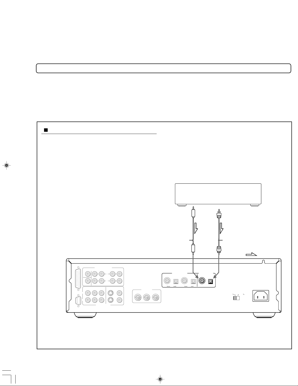
The DVD Player contains a high quality D/A converter which is used when
processing the digital audio signal recorded on DVD media. The DVD Player
can also function exclusively as a D/A converter. This feature lets you
enjoy high quality processing of digital audio signals from other components
in your entertainment system.
Making connections from other components
Before Connecting
•Refer to the instruction manuals supplied with any and all components that you plan to connect the DVD Player to.
•Be sure to turn off the power to all components to be connected and unplug them from the wall outlet before making any
connections.
•Make sure that analog audio connections are made from the CH1 or CH2 ANALOG OUTPUT jacks on the DVD Player to an amplifier or
receiver as described on pages 12 and 13.
Making digital connections
The DVD Player features an optical and a coaxial
digital input jack. The input is selected according to
the position of the Source input selector on the front
panel, making it possible to make connections to two
different components. The input is selected according
to the position of the Source input selector on the front
panel, making it possible to make connections to a CS
tuner, CD player, DAT recorder, or other devices that
output linear PCM audio signals with sampling rates of
32/44.1/48 kHz. Make connections from the DIGITAL
INPUT OPTICAL jack (DIGITAL 1) on the DVD Player to
the digital optical output on an audio component
using an optical fiber cable (sold separately). Make
connections from the DIGITAL INPUT COAXIAL jack
(DIGITAL 2) on the DVD Player to the digital coaxial
output on an audio component using a coaxial cable
(sold separately).
To digital
audio output
(coaxial)
Devices that output linear PCM audio
signals with sampling rates of
32/44.1/48 kHz
To digital audio
output (optical)
14
RDV-1(US_E)p10-21.p65 10/4/00, 17:0314
Coaxial cable
(not supplied)
Optical cable
(not supplied)
: Signal flow
RDV-1 US/Asia 29342995

5
Selecting the audio from connected components
Set the Source input selector to the External Input
position (Optical or Coaxial) that corresponds to the
connections made to the desired component.
If the component is connected to the DIGITAL INPUT
OPTICAL jack (DIGITAL 1), set to Optical. If the
component is connected to the DIGITAL INPUT COAXIAL
jack (DIGITAL 2), set to Coaxial.
Set the Source input selector to DVD to use the DVD
Player for disc playback, etc.
Notes
•When the Source input selector is set to either Optical or
Coaxial, only Standby/On on the front panel of the DVD Player
(or ON/STNBY on the remote controller) and DIMMER on the
remote controller can be used. All functions of the DVD Player
related to disc playback are disabled.
The audio sampling rate indicator on the front panel does not
light.
The remote control confirmation beep does not sound.
•When the position of the Source input selector is changed,
there may be a moment of silence before sound is produced.
This is not a malfunction.
•If a Dolby Digital or DTS digital signal is input during playback
of the selected source component, the signal can be
subsequently output without processing to an amp or other
component with decoding capabilities. When this is the case,
the sampling rate of the digital signal is not displayed.
•The DVD Player does not feature the ability to decode Dolby
Digital or DTS digital audio signals input from externally
connected components, and therefore no audio will not be
output from the discreet 5.1-channel ANALOG OUTPUT.
•When a linear PCM audio signal is input from a connected
component, the sampling rate is displayed.
•Please note that if the digital audio signal of a DTS CD or DTS
LD is input from a connected component, a loud noise will be
output from the ANALOG OUTPUT jacks.
1
2
3
When the DVD Player is in standby
mode, set the Source input selector
to the position corresponding to the
desired input.
Source
External Input
DVD
Optical
Coaxial
Press Standby/On on the front
panel.
Start playback on the selected
source component.
When selecting Optical
When selecting Coaxial
Sampling rate
RDV-1(US_E)p10-21.p65 10/4/00, 17:0315
RDV-1 US/Asia 29342995
1
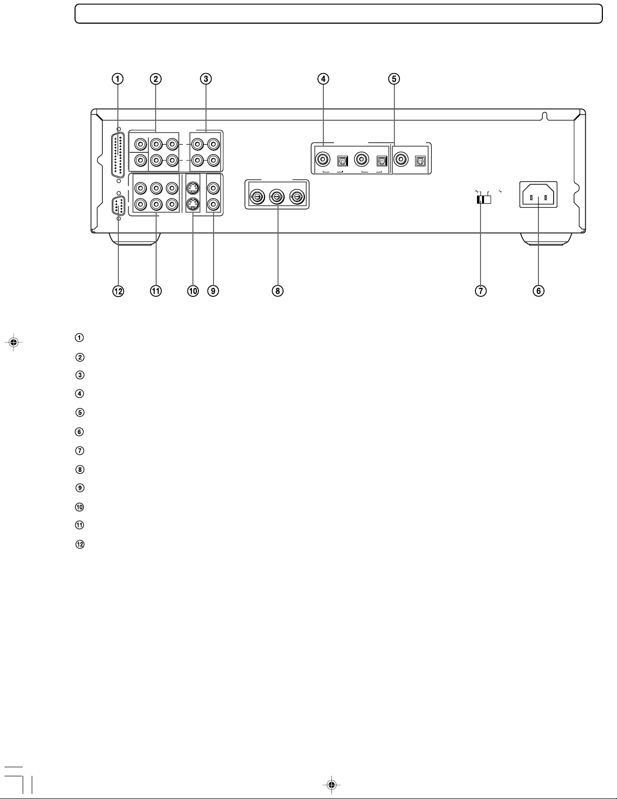
Rear panel
For operational instructions, see the page indicated in
brackets [ ].
ANALOG OUTPUT
RS 232 MULTI CHANNEL OUTPUT
CENTER
SUBWOOFER
CH 1
CH
2
YP
SURR FRONT CH
COMPONENT
B PR
VIDEO OUTPUT
L
R
2
1CH
VIDEOS VIDEO
VIDEO OUTPUT
COMPONENT
YPBP
R
OPTICAL
COAXIAL COAXIAL
CH 1
CH 2
OPTICAL
DIGITAL INPUTDIGITAL OUTPUT
COAXIAL OPTICAL
VOLTAGE SELECTOR
120 V
220 -230 V
AC INLET
5.1-Channel SURROUND AUDIO OUT MULTI CHANNEL OUTPUT terminal [13]
5.1-Channel ANALOG OUTPUT [12]
2-Channel ANALOG OUTPUT [10,12]
DIGITAL OUTPUT COAXIAL, OPTICAL [13]
DIGITAL INPUT COAXIAL (DIGITAL 2), OPTICAL (DIGITAL 1) [14, 15 ]
AC INLET [19]
VOLTAGE SELECTOR (Worldwide models only) [19]
COMPONENT (PROGRESSIVE) VIDEO OUTPUT (Y/P
B/PR)/ BNC jacks [11]
VIDEO output [10]
S VIDEO output [11]
COMPONENT (PROGRESSIVE) VIDEO OUTPUT (Y/P
B/PR)/ pin jacks [11]
RS 232 port (This port is to be used in conjunction with an external controller to control the operation of the
RDV-1 using an external device.)
16
RDV-1(US_E)p10-21.p65 10/4/00, 17:0316
RDV-1 US/Asia 29342995
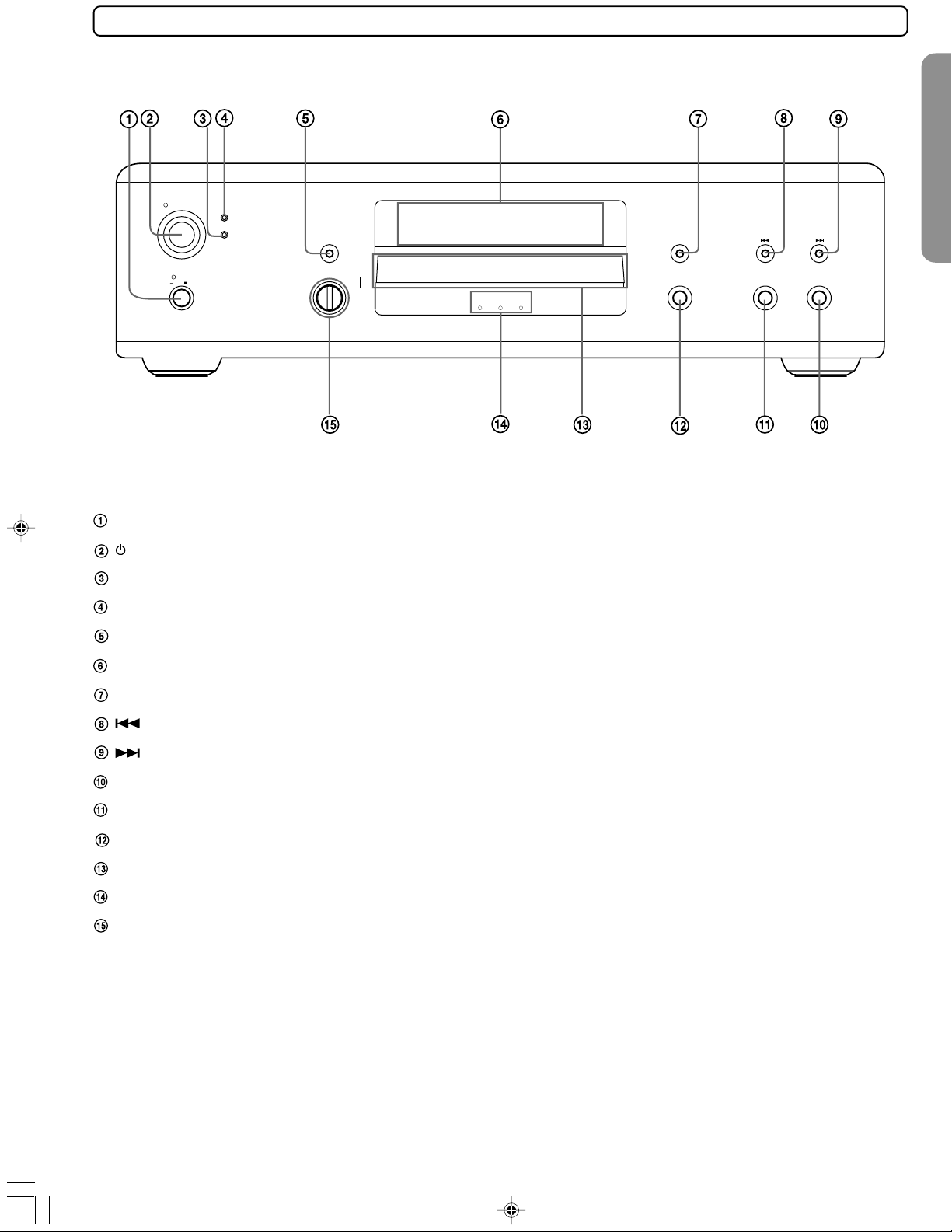
Front Panel
For operational instructions, see the page indicated in
brackets [ ].
Standby/On
Power
On
PROGRESSIVE SCAN
On
Standby
O f f
Power button [19]
Standby/On button [19]
Standby indicator [19]
Power indicator (19)
Video Circuit Off button [45]
Video Circuit Off
Source
DVD
Optical
Coaxial
External Input
VECTOR LINEAR CONVERTER
Sampling Rate (@@)
kHz
96/88.248/44.1 192 /176.4
Display
Open/Close
Stop Play
Front panel display [18]
Display button [18, 40]
button [28]
button [28]
Play button [22]
Stop button [23]
Open/Close button [22]
Disc tray [22]
Audio sampling rate indicators [22]
Source input selector [14, 15]
RDV-1(US_E)p10-21.p65 10/4/00, 17:0317
17
RDV-1 US/Asia 29342995
Display
For operational instructions, see the page indicated in
brackets [ ].
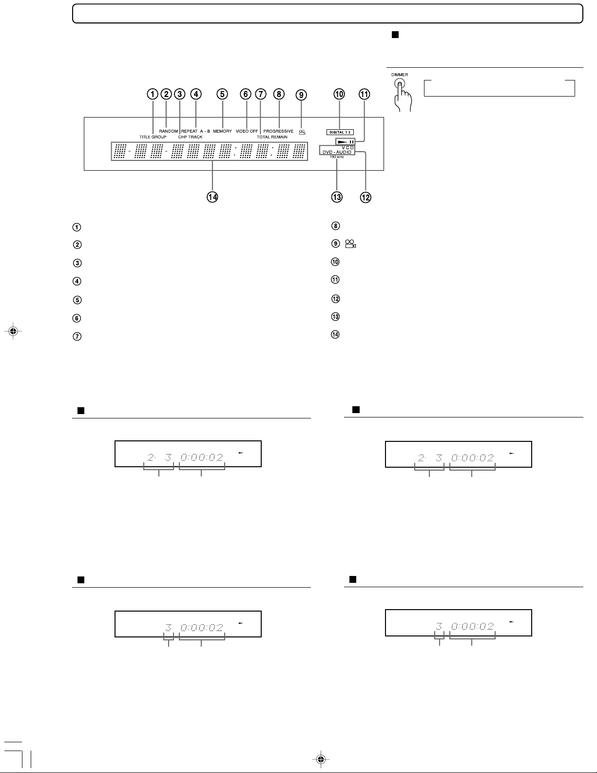
TITLE/GROUP indicator
RANDOM indicator [31]
CHP (Chapter)/TRACK indicator
REPEAT indicators [29]
MEMORY indicator [30]
Repeatedly pressing DIMMER on
the remote controller changes the
brightness of the display
→Normal→Dim→Ve ry Di m→OFF
PROGRESSIVE indicator [44]
Angle icon indicator [34]
DIGITAL 1/2 input indicators [15)
Play mode indicators
Inserted disc indicator [22]
VIDEO OFF indicator [45]
TOTAL playing time/REMAINING time elapsed
time indicator
192 kHz Processing indicator
Multifunction indicator (Indicates operating
status, messages, etc.)
By repeatedly pressing Display on the front panel of the DVD Player, you can switch between the elapsed time and
remaining time displays.
DVD-Video
During playback:
Example
Playing chapter
3 of title 2
TITLE CHP
DVD
Elapsed time of
the current
chapter
DVD-Audio
During playback:
Example
Playing track 3
of group 2
GROUP TRACK
DVD - AUDIO
Elapsed time of
the current track
Notes
•Some discs may not display chapter numbers.
•A time indication not accompanied with a chapter number
shows elapsed time of a segment within the current time.
Video CD
During playback:
CD
During playback:
Example
Playing track 3 Elapsed time of
TRACK
the current track
Note
Some discs may not display track numbers or elapsed time.
18
RDV-1(US_E)p10-21.p65 10/4/00, 17:0318
VCD
Example
Playing track 3
TRACK
CD
Elapsed time of
the current track
RDV-1 US/Asia 29342995
9
Before connecting the POWER
• The RDV-1 is shipped with the main power (Power) switch in the on position ( ON). When the power cord is plugged in
for the first time, the RDV-1 will automatically enter the standby state and the STANDBY indicator will light (same
condition after step 2 below).
• Make sure that all appropriate connections have been completed as described on pages 10 to 13.
• Turning on the DVD Player may cause a momentary power surge, which might interfere with other electrical equipment
such as computers. To prevent interference, use a wall outlet on a different circuit.
1
For models with a
voltage selector, set
VOLTAGE SELECTOR to
the position of your local
power line voltage.
If the preset voltage is not correct for
your area, insert a screwdriver into the
groove in the switch. Slide the switch all
the way to the right (120 V) or to the left
(220-230 V), whichever is appropriate.
VOLTAGE SELECTOR
220 -230 V
Standby/On
Power
On
PROGRESSIVE SCAN
120 V
On
Standby
Video Circuit Off
Source
External Input
DVD
Optical
O f f
Coaxial
VECTOR LINEAR CONVERTER
Sampling Rate (@@)
96/88.248/44.1 192 /176.4
2 Plug the supplied power cord
into the AC INLET and then into
the power outlet on the wall.
AC INLET
Power cord
(supplied)
Notes
• Do not use a power cord other than the one supplied with
the RDV-1. The power cord supplied is designed for use with
the RDV-1 and should not be used with any other device.
• Never have the power cord disconnected from the RDV-1
while the other end is plugged into the wall outlet. Doing so
may cause an electric shock. Always connect by plugging
into the wall outlet last and disconnect by unplugging from
the wall outlet first.
To a wall outlet
3 Press Power to switch on
the main power.
The DVD Player enters standby mode.
Display
Open/Close
kHz
Stop Play
The Standby indicator lights up.
Notes
• The buttons on the remote controller do not
operate if the Power switch is set to OFF.
• To switch off the main power, press Power again.
RDV-1(US_E)p10-21.p65 10/4/00, 17:0319
4 Press Standby/On on the DVD Player
or ON on the remote controller.
The DVD Player turns on. The Standby indicator turns off and the Power
indicator lights.
The first time you turn on the DVD Player, the Initial Setup screen
appears.
Press ENTER, then follow the procedure on page 55 to set up your DVD
Player for the first time.
Notes
• To put the DVD Player in the standby mode, press Standby/On on the DVD
Player, or STNBY (or ON) on the remote controller. Be sure to set the volume to
minimum before putting the DVD Player in the standby mode for the next use to
avoid sudden loud sound reproduction.
• While the Standby indicator lights up, the DVD Player can receive signals from
the remote controller. However, if you press Power on the DVD Player to switch
off the main power, the remote controller cannot be used to turn on the DVD
Player.
• You can change the First Setup later with “Customizing the Function Settings”
starting from page 46.
• Setting the Standby button to standby does not shut off the power completely.
RDV-1 US/Asia 29342995
1
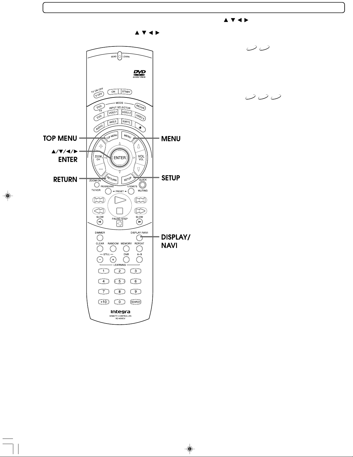
Using the Remote Control to Navigate On-screen Displays
On-screen navigation is a simple procedure that is done mostly by using / / / and ENTER on the supplied remote
controller. To move the highlighted section on the screen (cursor), simply press the edge of the button that corresponds
to the direction you wish to move in (
/ / / ). Press the center of the button (ENTER) to enter settings or selections.
DVD-A
About the disc menu
A DVD-Video or DVD-Audio may include more than one language
and more than one sound system. In many instances, such DVD let
you choose the language (e.g. disc menu language/audio
language/subtitle language), sound system, and so on using the
menu.
Depending on the disc, the name of the disc menu varies and the
disc menu may be included in the main menu.
About the title menu
DVD-Video, DVD-Audio, or Video CD with PBC (Playback Control)
function (see “About Video CDs” on page 7) may let you locate a
title, chapter, group, or track (see page 7) using the menu.
Depending on the disc, the name of the title menu varies and the
title menu may be included in the main menu.
DVD-V
DVD-V
DVD-A
VCD
The following buttons are also used in conjunction with onscreen navigation.
SETUP: Press to display the Setup screen when you
MENU and TOP MENU: These button select the menu screen(s)
DISPLAY/NAVI: This button displays information about the
RETURN: Press to return to a previous screen or setting.
wish to make changes or adjustments in the
DVD Player performance settings. For details
of the DVD Player settings, refer to
“Customizing the Function Settings” starting
from page 46.
recorded on DVD media.
current settings of the disc loaded in the
player and also offers a variety of playback
options (see page 40).
This button is convenient when you do not
wish to change a setting or selection.
20
RDV-1(US_E)p10-21.p65 10/4/00, 17:0320
RDV-1 US/Asia 29342995

Various sound formats and sound effects
Minimum speaker configuration for
DTS/Dolby Digital/MPEG2* surround sounds
Center
Speaker
Left front
speaker
Left
surround
speaker
The 5.1-channel digital surround format of DOLBY DIGITAL/
DTS/MPEG2* enables you to individually play five full-range
(20 Hz-20 kHz) channels (left and right front, center, two
surround channels) plus an LFE (Low Frequency Effect)
channel for the low-range effect sound. It will create a
realistic sound as heard in theaters and concert halls.
DOLBY DIGITAL Surround
DVD Video that have the
system.
DIGITAL
mark are recorded using this
DTS Surround
DVD Video and CD that have the mark are recorded using this
system.
MPEG2*
DVD Video that have the mark are recorded
using this system. MPEG2 may have 8 channels. In this case, left and
right center speakers in addition to the above speaker
configuration are used.
DOLBY PRO LOGIC Surround
This surround format consists of 4 channels (left and right front,
center, and monaural surround channel) and emphasizes the
center channel. This format is very effective for panning music,
conversation, and three-dimensional sound movement output from
three front channels. It also simulates the atmosphere and surround
effects of the sound reflected from the side and rear walls of the
theater.
DVD Video that have the mark are recorded using
this system.
* Not applicable for USA and Canadian models
Right
front
speaker
Right surround
speaker
RDV-1(US_E)p10-21.p65 10/4/00, 17:0421
21
RDV-1 US/Asia 29342995

Before playing
• DVD-Video, DVD-Audio, Video CD, CD, CD-R and CD-RW can be played with the DVD
Player (see “Playable Discs” on page 6). Do not play anything else.
• When playing DVD-Video, Video CD, or DVD-Audio with video features, turn on the TV
and set the TV to the DVD Player's input.
• If an audio system is connected to the DVD Player, turn on the audio system and set it
to the DVD Player’s input.
• Make sure that the Source input selector on the front panel is set to DVD.
CD
VCD
,
and CD marks in the pages related to disc operation
About the
DVD-A
DVD-V
VCD
CD
DVD-V
DVD-V, DVD-A
means the function or title is related to DVD-Audio operation.
means the function or title is related to DVD-Video operation.
means the function or title is related to Video CD operation.
means the function or title is related to audio CD operation.
DVD-A
VCD
Basic Playback
Warning
If the DVD Player is connected to the TV
or amplifier through the analog audio
jacks, do not play DTS-encoded discs.
Excessive noise may be output from the
analog stereo jacks, which may
damage the connected equipment.
To reproduce DTS surround sounds,
digital connection to an amplifier with a
DTS decoder is needed.
1 Press Open/Close.
The disc tray opens.
when the button is pressed
The DVD Player turns on and the disc
tray opens. In this case, it takes several
seconds until the disc tray opens.
2 Place a disc on the disc tray.
Put the disc in the tray with the label
side facing up.
If the DVD Player is in standby mode
There are two different disc sizes.
Place the disc in the correct guide
on the disc tray.
Standby/On
Power
On
On
Standby
O f f
Video Circuit Off
Source
DVD
Optical
External Input
Coaxial
Video Circuit Off
Source
External Input
DVD
Optical
Coaxial
VECTOR LINEAR CONVERTER
Sampling Rate (@@)
96/88.248/44.1 192 /176.4
Display
48/44.1 96/88.2 192/176.4
Open/Close
Whenever a disc is loaded in the
player, Stop and Play are
highlighted blue.
Display
kHz
Open/Close
Stop Play
PROGRESSIVE SCAN
3 Press Play.
The disc tray closes and playback starts.
If you press Open/Close to close the tray after
step 2, playback may automatically start
depending on the disc.
The appropriate disc indicator lights, and the audio
sampling rate indicator also lights.
For the other information that appears in the display,
see page 37.
22
RDV-1(US_E)p22-28.p65 10/4/00, 17:0422
DVD
48/44.1 96/88.2 192/176.4
CAUTION
Keep your fingers well clear of the disc tray as it is closing.
Neglecting to do so may cause serious personal injury.
RDV-1 US/Asia 29342995

If the screen on the right
appears - Screen Saver
If you pause for a long time, the
screen saver operates.
To resume normal playback, press
Play.
(You can set this function to Off
using the menu explained in
“Customizing the Function
Settings” starting from page 46.
See page 53 for direct
information.)
To remove the disc
Press to open the disc tray.
Remove the disc after the disc tray opens completely.
After removing the disc, be sure to press the button again to
close the tray.
To pause playback (still mode)/
Playing frame by frame
Press during playback.
To start playback, press .
DVD-V
To play frame by frame
Press the button repeatedly during pause. Each time you press the
button the picture advances one frame.
To resume normal playback, press .
Notes
• The sound is muted during still mode and frame by frame playback.
• When using a DVD-Audio that includes pictures, this operation may
be permitted in some picture segments.
VCD
Tip to obtain a higher quality picture
Occasionally, some picture noise not usually visible during a
normal broadcast may appear on the TV screen while
playing a DVD-Video because the high resolution pictures
on these discs include a lot of information. While the
amount of noise depends on the TV you use, you should
generally adjust the TV to reduce sharpness when viewing
DVD-Videos.
To play NTSC discs (Multisystem TV is needed)*
Set “PAL/Auto” to “Auto” using the menu explained in
“Customizing the Function Settings” starting from page 46.
See page 49 for direct information.
* Not applicable for USA and Canadian models
1
To stop playback
Press .
When you press
location where you stopped playback because the location
index is stored in memory.
Note
The location where playback resumes may vary depending on the disc
or the scene where you stopped.
Resuming playback from the beginning
Press
again after stopping playback to clear the location index
memory, then press to start playback.
DVD-V
DVD-A
VCD
To start playback from the beginning of the DVD-Video or DVD-Audio,
press to open the disc tray then press to close the disc tray and
start playback.
Notes
The location index memory will also be cleared when:
• The power cord is unplugged.
• The disc tray is opened.
• The parental lock setting is changed (see page 54) or a disc menu
language is selected (see page 52).
• The location where playback resumes may vary depending on the
disc or the scene where you stopped. With DVD-Audio, playback may
restart from the beginning of the track.
• To change the Audio Out Select (see page 50) or the On-Screen
Language (see page 52) settings, press after stopping playback to
clear the location index. Please note that resumed playback is not
possible after this is done.
Playback starts from the beginning of the current title.
Playback starts from the beginning of the current group.
CD
Playback starts from the beginning of the disc.
to restart playback, playback starts from the
3
Notes
• Do not move the DVD Player during playback. Doing
so may damage the disc.
•Use on the remote controller or DVD Player to
open and close the disc tray. Do not touch the disc
tray while it is moving. Doing so may cause the DVD
Player to malfunction.
• Do not press down on the disc tray or put any
objects other than playable discs on the disc tray.
Doing so may cause the DVD Player to malfunction.
• In many instances, a menu screen appears when
playback of a movie is complete. Prolonged display
of an on-screen menu may damage your television
set, permanently etching that image onto its screen.
To avoid this, be sure to press once the movie is
complete.
23
RDV-1(US_E)p22-28.p65 10/4/00, 17:0423
RDV-1 US/Asia 29342995

To play in fast reverse or fast forward
DVD-V
VCD
DVD-A
During normal playback, press for fast reverse playback or for
fast forward playback.
Each press of the same button changes the playback speed.
The rate and direction of playback is indicated by arrow marks (
or )
in the corner of the screen.
To resume normal playback.
Press .
Notes
• The DVD Player mutes sounds and omits subtitles during reverse and forward
scan of DVD-Video.
• The playback speed may differ depending on the disc.
• Fast reverse and fast forward playback may not be possible with some DVDAudio.
To play in slow-motion
DVD-V
Press SLOW during playback.
:Each time you press , the slow-motion speed changes.
:If you press during playback, you can view the picture in reverse
slow motion. (Only when using a DVD-Video.)
Each time you press
, the slow motion speed changes.
To resume normal playback.
Press .
Notes
• The sound is muted during slow-motion playback.
• The playback speed may differ depending on the disc.
• When using a DVD-Audio that includes pictures, this operation may be
permitted in some picture segments.
CD
VCD
To control still pictures
DVD-Audio may include still pictures, which are classified into two large
groups.
Slideshow: Still pictures appear one after another automatically
consistent with the disc program.
Browsable pictures:
STILL +/–: To select a picture. (The order of pictures vary
RETURN: To return to an initial one programmed on the disc.
You can display your favorite still picture selected with
the buttons on the remote control.
depending on the disc.)
DVD-A
24
RDV-1(US_E)p22-28.p65 10/4/00, 17:0424
RDV-1 US/Asia 29342995

5
RDV-1(US_E)p22-28.p65 10/4/00, 17:0425
RDV-1 US/Asia 29342995
2

The structure of the disc content
DVD-Audio
The contents of DVD-Audio are divided into
groups, and the groups are subdivided into tracks.
Group 1
Track 1 Track 2
Track 1 Track 2
DVD-V
DVD-Video
Normally, the contents of DVD-Video are divided
into titles, and the titles are subdivided into
chapters.
Title 1 Title 2
Chapter 1Chapter 2 Chapter 1
Chapter 2
Chapter 3
Locating a Title Using the Title Menu
If a DVD-Video contains a title menu, you can locate a specific title using the title menu function.
Notes
• The instructions above describe basic procedures which may
vary depending on the contents of the DVD-Video. If
different instructions appear on the TV screen, follow those
instructions.
• If you display the title menu during playback and press TOP
MENU again without selecting any title, the DVD Player
usually resumes playback from the point where you first
pressed TOP MENU. (There may be exceptional cases
depending on the disc.)
• This method of locating a title is available only on a disc that
contains a top menu.
• The name of the button in the instruction notes of discs varies
depending on the disc.
1
Press TOP MENU. (Depending on
the DVD-Video, press MENU.)
The title menu appears on the TV
screen.
Example of a title menu.
2
TITLE
TITLE
1
3
TITLE
TITLE
4
Group 2
Track 3
2
3
Press / / / to select the title
you want.
If the titles in the
title menu are
assigned a number,
you can also
directly locate a
specific title using
the number
buttons.
Press ENTER.
The DVD Player starts playback from
chapter 1 of the selected title.
26
RDV-1(US_E)p22-28.p65 10/4/00, 17:0426
RDV-1 US/Asia 29342995

Video CD/CD
Video CD and CD are divided into tracks.
Track 1 Track 2 Track 3 Track 4
DVD-A
DVD-V
VCD
CD
Track 5
Number
buttons
Locating a specific title and chapter or group and track by entering the numbers
If a DVD-Video or DVD-Audio contains the numbers corresponding to the titles and chapters, or group and tracks you
can locate a specific chapter in a specific title directly by entering the numbers.
1
2
3
Press SEARCH.
Skip steps 1 and 2 if you are using a
Video CD/CD.
The following display appears.
e.g.
DVD-V
1
Title:
Chapter:
1
Group:
Track :
DVD-A
1
1
Press / to select a section you
want to locate.
e.g. When you want to locate a chapter or
track.
e.g.
DVD-V
1
Title:
Chapter:
1
DVD-A
Group:
Track :
1
11
Press the corresponding number
buttons for the section you want.
e.g. To select chapter or track 25.
or
4
5
Notes
• Pressing CLEAR resets the numbers. To clear the display, press
SEARCH several times.
• This method of locating a title/group is available only on a
disc that contains title/group numbers.
Playing bonus groups of DVD-Audio
Some DVD-Audio may include an extra content called
“Bonus Group”.
If you select it to play, a display appears to enter a key
number. Press the number buttons on the remote
control to enter the key number.
When the number is entered correctly, playback of the
bonus group starts.
To get key numbers, refer to instruction note of discs.
Notes
• A key number may be called in some cases such as when
removing the disc. Enter the key number again if necessary.
• When you use a bonus group in a programmed play such as
memory playback, enter the key number beforehand.
Repeat steps 2 and 3 if necessary.
Press .
The DVD Player starts playback from
the selected section.
RDV-1(US_E)p22-28.p65 10/4/00, 17:0427
27
RDV-1 US/Asia 29342995

DVD-V
Standby/On
Power
On
O f f
PROGRESSIVE SCAN
DVD-A
On
Standby
VCD
Video Circuit Off
Source
External Input
DVD
Optical
Coaxial
CD
VECTOR LINEAR CONVERTER
Sampling Rate (@@)
kHz
96/88.248/44.1 192 /176.4
Open/Close
Display
Stop Play
Number
buttons
DVD-V
VCD
CD
Locating a Specific Chapter or Track
Consecutively
You can locate consecutive chapters or tracks.
Remote
controller
DVD Player
Press or (repeatedly) to
select the chapter or track you
wish to start playing.
Press once to start playback from
the beginning of the current chapter
or track.
Press
former chapters or tracks in reverse
order.
Press
chapter or track in order.
repeatedly to select the
repeatedly to select the next
Locating a Specific Location by
Entering the Time
You can locate a specific location by entering its
corresponding time (hours, minutes, and seconds).
1
2
Press SEARCH twice.
You may need to press the button
more than twice (depending on the
disc) until the following display
appears.
- : - - : -
Time
-
Press the number buttons to enter
the location’s time.
The entered number appears on the
right end of the field, then shifts to the
left each time the next number is
entered.
e.g.
Hours Minutes Seconds
1:25:30
Time
Notes
• Some titles may not display chapter numbers. Some groups
may not display track numbers.
• When you set “Title/Group Stop” to “Off” (see page 54), you
can locate consecutive chapters in another title or tracks in
another group. If you go back to the preceding title or group
by pressing , the DVD Player locates the first chapter of
the title or the first track of the group. When “Title/Group
Stop” is set to “On”, you can locate consecutive chapters or
tracks only within the current title or group.
28
Note
If the location time you enter exceeds the
total playing time of the disc, the setting
will be cancelled.
3
Press .
The DVD Player starts playback from
the entered location.
Notes
• Some discs may not respond to this procedure.
• Some scenes may not be located precisely.
• This method for accessing specific locations is available only
within the current title of the DVD-Video or within the current
track of the Video CD/CD.
RDV-1(US_E)p22-28.p65 10/4/00, 17:0428
RDV-1 US/Asia 29342995

9
You can play a specific title, group, chapter, track, or segment
Chapter Repeat
repeatedly (Title/Group repeat, chapter/track repeat, A-B repeat).
DVD-A
DVD-V
VCD
CD
DVD-V
VCD
CD
Repeating a Title, Group, Chapter, or
Track
You can play the same title, group, chapter, or track
repeatedly (Title/group, chapter/track repeat).
Press REPEAT.
Each time you press REPEAT, the repeat
mode changes as follows.
Chapter Repeat
DVD-V
→
DVD-A
Track Repeat Repeats the current
↓
DVD-V
Title Repeat Repeats the current
DVD-A
Group Repeat Repeats the current
VCD
Track Repeat Repeats the current
CD
Track Repeat Repeats the current
↓
DVD-V
DVD-A
All Repeat Repeats the entire
VCD
disc.
CD
↓
Repeat Off Resumes normal
To resume normal playback
Press CLEAR.
Repeats the current
chapter.
track.
title.
group.
track.
track.
playback.
Repeating a Specific Segment
You can play a specific segment repeatedly (A-B
repeat).
1
2
To resume normal playback
Notes
• Some discs may not permit A-B repeat operation.
• You can play a specific segment only within the current title,
chapter, or track.
• You cannot set the A-B repeat function for segments that
include multiple camera angles.
• There may be a slight difference between point A and the
location where playback actually resumes depending on
the disc.
Press A-B at the beginning of the
segment (point A) you want to
play repeatedly.
A–
Press A-B again at the end of the
segment (point B).
A–B
The DVD Player automatically returns
to point A and starts repeat playback
of the selected segment (A-B).
Press CLEAR.
Note
• Some discs may not permit repeat operation.
• When playback is stopped, be sure to press within about
5 seconds after you select the repeat play mode.
RDV-1(US_E)p29-37.p65 10/4/00, 17:0429
RDV-1 US/Asia 29342995
2

Title : 2
Title : 2
Chapter : 25
Chapter : 25
Title : 2
Title : 2
Chapter : 12
Chapter : 12
Title : 1
Title : 1
Chapter : 1
Chapter : 1
You can combine your favorite titles, groups, chapters, or tracks
and play them in any order. You can program up to 30
Number
buttons
selections into the memory (Memory playback).
DVD-A
DVD-V
VCD
CD
Setting Titles, Groups, Chapters, or Tracks in a Favorite Order
The DVD Player automatically plays titles, groups, chapters, or tracks in the order you program.
VCD
1
2
Insert a disc and press MEMORY
while the disc is stopped.
The following display appears.
Memory List
1 TG: -- CT: -2 TG: -- CT: -3 TG: -- CT: -4 TG: -- CT: -5 TG: -- CT: -6 TG: -- CT: -7 TG: -- CT: --
TG: Title number or group number
CT: Chapter number or track number
DVD-A
DVD-V
1 Press the number button(s) to
enter the title or group number.
2 Press to highlight “--” below CT.
3 Press the number button(s) to
enter the chapter or track
number.
4 Press ENTER to confirm.
To select another chapter/track in the
same title/group
Press the number button(s) for another
chapter/track.
e.g. To play chapter 25 in title 2, chapter 12
in title 2, all the chapters in title 1, and
chapter 2 in title 4.
Title number Chapter number
3
To change the entered step
While the Memory List is displayed, press / to
highlight the item. To select another title/chapter,
group/track, or track, follow step 2.
To cancel the entered step
While the Memory List is displayed, press / to
highlight the item. To cancel, press CLEAR.
To resume normal playback
Press CLEAR.
The memory playback indicator disappears.
CD
Press the number button(s) to
select the track number, then press
ENTER to confirm.
Repeat this step to select the next
track.
The space of “TG” may be showing a
number. Neglect this number when using a
Video-CD/CD.
While the Memory List is displayed,
press
The DVD Player starts memory
playback.
.
Step 1
Step 2
Step 3
Step 4
30
RDV-1(US_E)p29-37.p65 10/4/00, 17:0430
To program during playback
If you press MEMORY during playback, the display to
accept your programming appears. To display the
Memory List, press QUICK, press / to select Memory
List, then follow steps 2 and 3.
Notes
• You can also use (plus ten button) to add ten to the
number.
• Some discs may not permit memory playback operation.
• If you press REPEAT during memory playback, the DVD Player
repeats the current memory playback.
• If you press MEMORY or RETURN while the “Memory List”
display appears on the TV screen, the “Memory List” display
disappears.
• The programmed selections will be cleared when you turn off
the DVD Player.
RDV-1 US/Asia 29342995

Title : 1
Chapter Random
TITLE : 1
CHAPTER : 3
Chapter : 3
Title : 2
Title : 2
Title : 2
Chapter : 2
Chapter : 2
Chapter : 2
Title : 3
Chapter : 1
You can play titles, chapters within a title, or tracks in random
order (Random playback).
DVD-V
VCD
CD
Playing Titles, Chapters or Tracks in Random Order
The DVD Player automatically selects the titles in DVD-Video, or tracks in Video-CD, CD, and plays them randomly.
Press RANDOM repeatedly to
change the random play mode as
follows.
→
DVD-V
Chapter Random
↓
DVD-V
Title Random Plays the titles in
VCD
Track Random Plays the tracks in
CD
Track Random Plays the tracks in
↓
Random Off Resume normal
If you press RANDOM during playback,
the DVD Player automatically starts
random playback after finishing the
current title, chapter or track.
Plays the chapters
within the current
title in random
order.
random order.
random order.
random order.
playback.
To resume normal playback
Press CLEAR.
Notes
• Some discs may not permit random playback operation.
• You cannot use the random playback function together with
the memory playback function.
• If you press during random playback, the DVD Player
goes to another title or track and continues random
playback.
Note
When playback is stopped, be sure to press within about 5
seconds after you select the random play mode.
RDV-1(US_E)p29-37.p65 10/4/00, 17:0431
31
RDV-1 US/Asia 29342995

You can magnify areas within a picture.
DVD-V
Zooming a Picture and Shifting the Zoom Point
You can zoom in on a picture. You can also shift the zoom point.
ZOOM +/–
ZOOM ON
CLEAR
Press ZOOM ON during normal,
slow, or still playback.
Adjust the magnification of the screen
using ZOOM + (to enlarge) and ZOOM
– (to reduce).
To shift the zoom point
Press / / / .
To restore the original zoom point (center
of the picture)
Press CLEAR.
To resume normal playback
Press ZOOM ON repeatedly so that “Zoom
Off” appears.
Notes
• Some discs may not permit zoom operation.
• During some scenes, the buttons may not work as described
above.
• Zooming does not work on subtitles or menu screens
included on DVD-Video.
• While a zoom operation is being performed, it is not possible
to select the DVD menu. To select the DVD menu, cancel the
zoom operation to resume normal playback, and then select
the DVD menu.
• The magnification level varies depending on the picture size
you select
(See pages 46 and 48).
• When using a DVD-Audio disc that includes pictures, this
operation may be permitted in some picture segments.
32
RDV-1(US_E)p29-37.p65 10/4/00, 17:0432
RDV-1 US/Asia 29342995

You can view a picture with less video noise.
DVD-V
VCD
Selecting DNR Picture Enhancement
Press DNR on the remote controller
during playback.
The current setting is displayed.
Each time you press DNR, the setting
changes as follows.
3D DNR On
3D DNR Expanded
3D DNR Off
3D DNR: Three Dimension Digital Noise
Reduction
Normal level
Expanded
level
Off
Notes
• Actual picture enhancement may vary depending on the
quality of the disc.
• Depending on the DNR setting selected, there may be no
improvement in the picture quality. When this is the case, set
DNR to “Off”.
• Depending on the DNR setting, some kinds of picture details
may be lost by the picture enhancement.
• Depending on the disc, some kinds of picture details may be
lost by the picture enhancement.
• When using a DVD audio disc that includes pictures, this
operation may be permitted in some picture segments.
RDV-1(US_E)p29-37.p65 10/4/00, 17:0433
33
RDV-1 US/Asia 29342995

Angle : 2 Angle : 3Angle : 1
You can select a preferred camera angle to watch a scene.
DVD-V
Changing the Camera Angle
If the scene was record ed from multiple angles, you can easily change the camera angle of the scene you are
watching.
To disable the angle icon display on the TV
Set “On-Screen Displays” to “Off” using the setting menu
(see pages 46 and 53).
Monitor the DVD display when you want to change the
camera angle.
Notes
• You can change the camera angle during still playback. The
camera angle changes to the new setting when you resume
normal playback.
• If you pause a picture immediately after changing the
camera angle, the resumed playback picture may not use
the new camera angle.
• When using a DVD-Audio that includes pictures, if there are
sections during which multiple angles are recorded, it may
be possible to change the camera angle.
1
Press ANGLE while playing a scene
recorded with multiple angles.
While playing a scene recorded with
multiple angles, the angle icon (
appears in the DVD display and on the
TV screen.
Press ANGLE while the angle icon is
displayed.
Angle: 1/5
)
Angle icon
Current
angle
number
2
Press ANGLE or while the angle
number is displayed on the TV
screen.
Each time you press ANGLE or , t h e
camera angle changes.
Angle: 1/5
Angle: 2/5
Angle: 3/5
: Cycles backwards
You can also change the camera
angle directly by pressing the number
buttons corresponding to the angle
number.
To turn off thr angle number display
Press CLEAR.
34
RDV-1(US_E)p29-37.p65 10/4/00, 17:0434
RDV-1 US/Asia 29342995

5
Good evening!
You can display subtitles on the TV screen and select a subtitle language
from those included on the DVD-Video.
DVD-V
Bon soir! ¡Buenas tardes!
DVD-V
Selecting a Subtitle Language
You can select a subtitle language from those included
on the DVD-Video.
1
2
Press SUBTTL during playback.
The current subtitle setting is displayed
for about 3 seconds.
Subtitle: ENG On
The abbreviation of the language
appears instead of the language
name. See the list of languages and
their abbreviations on page 55.
1
Language
Press SUBTTL or while the subtitle
setting is displayed on the TV
screen.
Each time you press SUBTTL or , the
subtitle languages included on the
DVD-Video disc change.
e.g.
Subtitle1ENG :
On
Turning Subtitles On/Off
1
2
Press SUBTTL during playback.
The current subtitle setting is displayed
for about 3 seconds.
Press / while the subtitle setting is
displayed on the TV screen, to select
“On” or “Off”.
Subtitle : 1 ENG On
Good evening!
Subtitle : 1 ENG Off
Displayed
for about
3 seconds
Subtitles
Subtitle2FRE :
Subtitle3SPA :
: Cycles backwards
To turn off the subtitle setting display
Press CLEAR.
Notes
• When you turn on the DVD Player or replace a disc, the DVD
Player returns to the automatic setting in the setting menu
(see pages 46 and 52).
When you select a subtitle language which is not included
on the disc, the DVD Player plays the prior language
programmed on the disc.
• During some scenes, the subtitles may not appear
immediately after you change the subtitle language by
pressing / .
On
On
Notes
• Some DVD-Video are set to display subtitles automatically,
and you cannot turn them off even if you set the subtitle
function to off.
• During some scenes, the subtitles may not appear
immediately after you select “On”.
• Some DVD-Video will allow you to make subtitle selections
and turn subtitles on or off only by using the disc menu.
• When using a DVD-Audio that includes pictures, if subtitle
information has been recorded on the disc, it may be
possible to select a subtitle language.
3
RDV-1(US_E)p29-37.p65 10/4/00, 17:0435
RDV-1 US/Asia 29342995

Good morning!
Bon jour!
¡Buenos días!
You can select a preferred audio language and sound system.
DVD-A
DVD-V
Selecting a Playback Audio Setting
You can select the preferred audio language and sound
system as a set from those included on the disc. This
function lets you temporarily change the audio
language which you selected as the automatic setting
in the setting menu (see pages 46 and 52), and choose
the sound system if the disc is recorded in more than one
sound format.
1
Press AUDIO during playback.
DVD-V
e.g.
Audio:
Audio OUT Select : Bitstream
The abbreviation of the language
appears. Refer to the list of languages
on back cover page.
Audio language
ENG PCM 2CH
1
Sound system
Audio channel
Audio Out
Select (except
for DVD-Audio)
(see page 50)
ENTER
Notes
• Depending on the disc, it may be necessary to select the
audio sound track using the DVD menu. When this is the case,
press MENU to open the DVD menu and select the
appropriate sound track as indicated on the DVD menu
screen.
• When the DVD Player is turned on or when the disc is
changed, the audio settings are restored to the presets. In
some cases, a language recorded on the disc may be given
priority and selected automatically when the disc is loaded
regardless of the setting.
• Depending on the DVD-Audio, the sampling frequency and
bitrate may be displayed.
• When using a DVD-Audio, changing the audio sound track
may cause playback to start again from the beginning of
the current track.
2
Press while the audio setting is
displayed on the TV screen.
Each time you press AUDIO or , th e
language and audio recording system
set changes.
DVD-V
e.g.
Audio:
Audio:
Audio:
: Cycles backwards
To turn off the audio setting display
Press CLEAR.
Notes
•Dolby Digital 5.1 Channel sound may be
displayed as “ D 6CH”.
•You can change the “Audio Out Select”
setting temporarily by pressing / .
•When using a DVD-Audio, it is not possible
to change the “Audio Out Select” setting.
•Before changing the setting, read through
the explanation on “Audio Out Select” on
page 50 and carefully select the setting.
ENG
1
ENG 2CH
PCM
2
FRE 5.1CH
3
5.1CH
VCD
Selecting Sound Channels on Video
CD
A Video CD may have left and right sound channels
which contain sounds or languages on each channel.
You can switch these two channels to hear a preferred
sound or language.
During playback, press AUDIO
(repeatedly) to select the sound
channel.
L.R
L
R
Both the left and right
channels are heard.
The left channel is heard.
The right channel is heard.
36
RDV-1(US_E)p29-37.p65 10/4/00, 17:0436
RDV-1 US/Asia 29342995

Audio Output from the DIGITAL OUTPUT and ANALOG OUTPUT Jacks Corresponding
to Disc Formats and the DVD Player Settings
Audio Out Select setting and the output jacks
Disc
DVD Video
Video CD
CD
Sound System
DOLBY DIGITAL Bitstream 48 kHz/20 bit Bitstream 48 kHz/20 bit 48 kHz/16 bit 48 kHz/20 bit
48 kHz/16 bit 48 kHz/16 bit 48 kHz/16 bit 48 kHz/16 bit 48 kHz/16 bit 48 kHz/16 bit 48 kHz/16 bit
48 kHz/20 bit 48 kHz/16 bit 48 kHz/20 bit 48 kHz/16 bit 48 kHz/20 bit 48 kHz/16 bit 48 kHz/20 bit
Linear
PCM
Linear PCM 44.1 kHz/16 bit
48 kHz/24 bit 48 kHz/16 bit 48 kHz/24 bit 48 kHz/16 bit 48 kHz/24 bit 48 kHz/16 bit 48 kHz/24 bit
96 kHz/16 bit 48 kHz/16 bit 48 kHz/16 bit — 96 kHz/16 bit 48 kHz/16 bit 48 kHz/16 bit
96 kHz/20 bit 48 kHz/16 bit 48 kHz/20 bit — 96 kHz/20 bit 48 kHz/16 bit 48 kHz/20 bit
96 kHz/24 bit 48 kHz/16 bit 48 kHz/24 bit — 96 kHz/24 bit 48 kHz/16 bit 48 kHz/24 bit
DTS Bitstream — Bitstream — — —
MPEG2* Bitstream 48 kHz/16 bit Bitstream 48 kHz/16 bit 48 kHz/16 bit 48 kHz/16 bit
MPEG1
DTS Bitstream
Notes
• Multi channel Dolby Digital and MPEG2* sound tracks recorded on DVD-Video are output as
downmixed 2-channel stereo.
• During playback of discs recorded with sampling rates higher than 48 kHz (for example 96 kHz), the
48/44.1 sampling rate indicator lights when Audio Out Select is set to either Bitstream or PCM.
Bitstream Analog 2Ch PCM
DIGITAL ANALOG DIGITAL ANALOG DIGITAL ANALOG
OUTPUT OUTPUT OUTPUT OUTPUT OUTPUT OUTPUT
44.1 kHz/16 bit 44.1 kHz/16 bit 44.1 kHz/16 bit 44.1 kHz/16 bit44.1 kHz/16 bit 44.1 kHz/16 bit
44.1 kHz/16 bit 44.1 kHz/16 bit 44.1 kHz/16 bit 44.1 kHz/16 bit44.1 kHz/16 bit 44.1 kHz/16 bit
(Noise is output)
Bitstream
(Noise is output)
Bitstream
(Noise is output)
—: No signal
* Not applicable for USA and Canadian models
Disc Sound System
Linear
DVD Audio
PCM
or
packed
PCM
44.1 kHz/16 bit 44.1 kHz/16 bit
48 kHz/16 bit 48 kHz/16 bit
44.1 kHz/20 bit 44.1 kHz/20 bit
48 kHz/20 bit 48 kHz/20 bit
44.1 kHz/24 bit 44.1 kHz/24 bit
48 kHz/24 bit 48 kHz/24 bit
88.2 kHz/16 bit 88.2 kHz/16 bit
96 kHz/16 bit 96 kHz/16 bit
88.2 kHz/20 bit 88.2 kHz/20 bit
96 kHz/20 bit 96 kHz/20 bit
88.2 kHz/24 bit 88.2 kHz/24 bit
96 kHz/24 bit 96 kHz/24 bit
176.4 kHz/16 bit 176.4 kHz/16 bit
192 kHz/16 bit 192 kHz/16 bit
176.4 kHz/20 bit 176.4 kHz/20 bit
192 kHz/20 bit 192 kHz/20 bit
176.4 kHz/24 bit 176.4 kHz/24 bit
192 kHz/24 bit 192 kHz/24 bit
ANALOG
OUTPUT
Notes
• With DVD-Audio, the “Audio Out Select” setting is not applicable.
• With DVD-Audio, there is no output from the DIGITAL OUTPUT jacks.
RDV-1(US_E)p29-37.p65 10/4/00, 17:0437
37
RDV-1 US/Asia 29342995

Pressing one button can display a graphics
based on-screen remote control that allows you
to control playback as if you were doing it from
the actual remote control.
DVD-V
VCD
CD
Using the Virtual Remote Control
1
2
During playback, press V.REMOTE.
The graphic remote controller (Virtual
Remote) appears on the screen.
DVD-V
e.g.
Title: 1@ 0:12:34 Play
@
Audio
Subtitle
Angle
Navi
0:01:23
Switch the audio
sound track and
video selection.
Change the
speed and
direction of
playback.
Chapt.: 2
Press / / / to select a desired
item, and press ENTER.
: Pause [23]/Frame by frame [23]
: Normal playback [22]
: Slow [24]
: Forward skip [28]
: Fast forward [24]
: Reverse slow [24]
: Reverse skip [28]
: Fast reverse [24]
Navi: Accesses the Navi menu (DVD-
Video only) [40]
Audio: Move the cursor control (
select a desired audio language,
and press ENTER.
For details, see page 36.
Selecting the output sound
format is not possible here.
Subtitle: Move the cursor control ( / ) to
select a desired subtitle
language, and press ENTER.
For details, see page 35.
Angle: Move the cursor control (
select a desired camera angle,
and press ENTER.
For details, see page 34.
/ ) to
/ ) to
To turn off the Virtual Remote
Press V.REMOTE.
Note
Some discs may not permit this operation.
38
RDV-1(US_E)p38-45.p65 10/4/00, 17:0538
RDV-1 US/Asia 29342995

9
Pressing one button can display a list of playback
functions which are relevant to your current
playback mode. You can check and modify
them from the list.
DVD-A
DVD-V
VCD
CD
Selecting the Playback Function
1
2
During playback, press QUICK.
The following on-screen display appears.
(The actual display will vary depending on
the playback status.)
DVD-V
e.g.
Quick
Memory
Memoy List
Repeat
Random
Bit Rate
Text
Exit
Press / to select a desired item,
and press ENTER.
e.g. To change the repeat mode:
Quick
Memory
Repeat
Random
Bit Rate
Text
Exit
A-B (Set A)
Chapter
Title
All
Memoy List
Quick menu
For details, see the respective pages.
Memory: To program memory playback
(see page 30).
Memory List: To list memory settings (see page 30).
Repeat: To select the repeat playback mode
(see page 29).
Random: To select the random playback mode
(see page 31).
BitRate: To activate/disable the bitrate display
(see page 40).
Text: To activate/disable the Text display.
Text display:
Displays DVD-Text data or CD-Text data if
included on the disc.
With DVD-Audio, Album text data is
displayed if it is recorded on the disc. Track
information is not displayed.
(Some text content recorded on the disc
may not be displayed properly depending
on the disc.)
Exit: To quit the on-screen display.
Note
Pressing QUICK again also exits the on-screen display.
3
Press / to change the setting.
e.g. To select the chapter repeat mode:
Quick
Memory
Memoy List
Repeat
Random
Bit Rate
Text
Exit
4
RDV-1(US_E)p38-45.p65 10/4/00, 17:0539
Press ENTER.
The on-screen display disappears and
playback will resume according to
your selection.
A-B (Set A)
Chapter
Title
All
RDV-1 US/Asia 29342995
3

Navi
V-Remote
The NAVI menu provides an icon based display
from which you can easily access key playback
function.
DVD-A
DVD-V
VCD
CD
NAVI menu items
1
2
Press DISPLAY/NAVI.
The NAVI menu appears.
Angle Viewer
Zoom
Z
Strobe Viewer
Each time you press DISPLAY/NAVI,
the display changes.
Title/Chapter:
Audio: Current audio setting.
Subtitle: Current subtitle setting.
Angle: Current angle setting.
Bit Rate: Data transfer rate (Mbit/s)
Status display (playback mode, current
DNR setting, current zoom status, etc.)
When a DVD-Audio is loaded in the player,
depending on the audio format (sampling
frequency/bitrate) the corresponding
indicators are displayed as follows.
C (mono)
The audio is monaural.
L, R (L: Left channel, R: Right channel)
The audio is in stereo.
Lf, Rf, C, LFE, S, Ls, Rs
(Lf: Left front, R: Right front, C: Center,
LFE: subwoofer, S: Surround, Ls: Left surround,
Rs: Right surround)
The audio is multi channel.
V-Remote
Title: 1 0:00:00
Chapter: 1 0:00:00
Audio ENG1 5.1 CH
Subtitle ENG1 ON
Angle 1/5
Bit Rate: IIIIIIIIIIIII
Elapsed time and remaining
time of the current title/
chapter.
Amount of picture, sound and
subtitle data in the DVD-Video
disc transferred per second.
The larger the value, the more
data processed, but this does
not necessarily insure better
picture quality.
Capture
Navi
DNR
Preview
Press / / / to select a desired
feature icon.
For details on each feature, refer to
the list on this page.
3
4
Press ENTER.
Selection details appears.
Refer to the list on the next page
and follow the instructions detailed
on subsequent pages.
Notes
• The NAVI menu will disappear by pressing DISPLAY/NAVI
several times.
• The number of feature icons on the display will vary
depending on the disc.
• Feature icons are displayed only when you play a DVD-
Video.
Navi menu selections
You can control key playback functions
using the graphic based on-screen control
(Virtual Remote) (see page 38).
Angle Viewer
You can display all camera angles
simultaneously and select your preferred
one from them (see page 41).
Zoom
Z
You can magnify areas within a picture
(see page 32).
You can divide a desired scene into stop
action frames for careful analysis (see
page 41).
Strobe Viewer
You can display thumbnail views of the first
scenes of titles or chapters and select a
Preview
preferred one (see page 42).
DNR
You can view a picture with less video
noise (see page 42).
40
RDV-1(US_E)p38-45.p65 10/4/00, 17:0540
Capture
You can sample a scene from a playback
picture and transform it into a background
picture (see page 43).
RDV-1 US/Asia 29342995

Angle Viewer
You can display all camera angles
simultaneously and select your
preferred one from them.
You can divide a desired scene into
stop action frames for careful analysis.
Strobe Viewer
After selecting this icon and pressing ENTER, the following
on-screen display appears:
e.g.
When the scene contains 9 camera angles:
1
2
123
456
789
Angle Viewer
Navi Exit
Press / / / to select.
1-9: To select the camera angle.
Navi: To return to the NAVI menu.
Exit: To quit the on-screen display.
Press ENTER.
After selecting this icon and pressing ENTER, the following
on-screen display appears:
e.g.
Slow
Strobe Viewer
1
2
Normal Fast
ExitNavi
Press / / / to select.
Slow: Still pictures at shorter intervals.
Normal:Still pictures at normal intervals.
Fast: Still pictures at longer intervals.
>>: To view the next series of 6 pictures.
Navi: To return to the NAVI menu.
Exit: To quit the on-screen display.
Press ENTER.
Note
Some discs or scenes may not permit this operation.
RDV-1(US_E)p38-45.p65 10/4/00, 17:0541
Note
Some discs or scenes may not permit this operation.
41
RDV-1 US/Asia 29342995

NAVI menu items
You can display thumbnail views of
the first scenes of titles or chapters
and select a preferred one.
Preview
After selecting this icon and pressing ENTER, the following
on-screen display appears:
e.g.
1
123
456
Title Chapter Interval
ExitNaviNaviPreview
Press / / / to select.
1 - 6: To locate the scene.
Title: To display the first scene of titles (1
to 6).
Chapter: To display the first scenes of
chapters (1 to 6).
Interval: To display scenes at intervals of
about 10 minutes apart.
<<: To go to the previous page.
>>: To go to the next page.
Navi: To return to the NAVI menu.
Exit: To quit the on-screen display.
DNR
After selecting this icon and pressing ENTER, the following
on-screen display appears.
e.g.
3D DNR Expanded
1
2
You can view a picture with less video
noise.
DNR
3D DNR On
3D DNR Off
Press / to select.
3D DNR On: Normal level.
3D DNR Expanded: Expanded level.
3D DNR Off:Off.
Press ENTER.
2
Notes
• Some discs or scenes may not permit this operation.
• Some items may not be selected depending on the disc or
scene.
• Some of the first scenes may not be picked up depending
on the disc.
Press ENTER.
42
RDV-1(US_E)p38-45.p65 10/4/00, 17:0542
Note
For details and notes on the DNR picture enhancement, see
page 33.
RDV-1 US/Asia 29342995

Capture
After selecting this icon and pressing ENTER, the following
on-screen display appears.
e.g.
Capture
Storing
You can sample a scene from a
playback picture and transform it into
a background picture.
Navi
Exit
1
2
3
Notes
• You can store only one picture. Storing a new picture will
erase the old one.
• No operations are permitted during the process of the
sampling and storage of background picture.
want to capture.
Press / to select.
Storing: To sample and store the current
picture in the player memory.
Navi: To return to the NAVI menu.
Exit: To quit the on-screen display.
Press ENTER.
The stored picture will be displayed as
a background picture when the
player is in the stop mode. It is
necessary to confirm this process via
the setup menu (see page 52).
Pause playback at a scene you
RDV-1(US_E)p38-45.p65 10/4/00, 17:0543
43
RDV-1 US/Asia 29342995

The DVD Player is capable of outputting
progressive scan video. As its name suggests,
progressive scan delivers the video image
sequentially across the horizontal lines of the TV
or monitor rather than the alternating odd and
even delivery of an interlace scan. The result is a
picture quality that best reflects the quality digital
video recorded on the DVD.
DVD-V
VCD
Selecting progressive scan
PROGRESSIVE
Press PROGRESSIVE on the remote
controller.
The PROGRESSIVE indicator lights in the
front panel.
To turn off the progressive scan, press
the button again until the
PROGRESSIVE indicator disappears.
Notes
• In order for this function to be effective, it is necessary to
have made component video connections to a TV or
monitor that is compatible with progressive scan.
• This function only works when the color system recorded on
the disc is NTSC.
44
RDV-1(US_E)p38-45.p65 10/4/00, 17:0544
RDV-1 US/Asia 29342995

5
The DVD-Player can be set playing audio
exclusively. In this case, you can obtain sound of
better quality, as the DVD Player does not process
video signals. (All the video output jacks send no
video signals.)
DVD-A
DVD-V
VCD
CD
Switching the video signal off
Standby/On
On
Standby
Video Circuit Off
Source
Power
On
O f f
PROGRESSIVE SCAN
External Input
DVD
Optical
Coaxial
VIDEO CIRCUIT OFF
VECTOR LINEAR CONVERTER
Sampling Rate (@@)
kHz
96/88.248/44.1 192 /176.4
DVD Player
VIDEO CIRCUIT
OFF
Remote
controller
Press VIDEO CIRCUIT OFF on the
DVD Player or V.OFF on the remote
controller repeatedly.
The VIDEO OFF indicator appears on the
display.
To turn on the video circuitry, press the
button again.
Notes
• Some discs cannot be played without some on-screen menu
interaction. If this is the case, be sure to perform the onscreen procedures as indicated before turning off the video
signal processing circuitry.
• The VIDEO CIRCUIT OFF setting is canceled whenever the
DVD Player is turned off.
RDV-1(US_E)p38-45.p65 10/4/00, 17:0545
RDV-1 US/Asia 29342995
4

When you insert a DVD-Video, DVD-Audio, Video CD, or CD, the various
functions of the DVD Player will be set (reset) according to the setting
menu.
You can customize this setting menu according to your preferences.
DVD-A
DVD-V
VCD
CD
Making Adjustments to Setting
ENTER
RETURN
SETUP
1
2
Press SETUP.
The following setting menu appears.
Category
Picture
TV Shape
Blacker than Black
Setting : Interlaced
Setting : Progressive
Progressive 4:3 Output
Progressive Conversion
PAL/Auto
4:3 LB
Off
1
1
Full
Auto
Auto
symbols
Press / to select a category
symbol for the setting you want to
change.
Picture performance settings
Output sound settings
Language settings
Display settings
4
5
6
Press / to change the setting,
then press ENTER.
e.g. When you change the “TV Shape”
setting to “16:9 Widescreen”.
Picture
TV Shape
Blacker than Black
Setting : Interlaced
Setting : Progressive
Progressive 4:3 Output
Progressive Conversion
PAL/Auto
4:3 LB
Off
1
1
Full
Auto
Auto
4:3 LetterBox
4:3 Normal
16:9 Widescreen
Further steps may be needed
depending on the item or setting.
Follow the steps described in the
explanation of each item starting
from page 50.
• To change the setting of other
items in the same category,
repeat steps 3 to 4.
• To change the setting of an item
in a different category, repeat
steps 2 to 4.
46
3
Operational setting
Initial settings
Press / to select the item you
want to change, then press ENTER.
e.g. When you select “PICTURE” as the
category in step 2, then select “TV
Shape” as the item in this step.
Picture
TV Shape
Blacker than Black
Setting : Interlaced
Setting : Progressive
Progressive 4:3 Output
Progressive Conversion
PAL/Auto
4:3 LB
Off
1
1
Full
Auto
Auto
4:3 LetterBox
4:3 Normal
16:9 Widescreen
7
To close the setting menu, press
SETUP.
To return to the previously displayed menu
Press RETURN.
Notes
•The on-screen display disappears when you press SETUP.
•SETUP can function even during normal playback, however
some operations may be inaccessible, and a message will
appear. In this case, try again after playback is stopped.
RDV-1(US_E)p46-55.p65 10/4/00, 17:0546
RDV-1 US/Asia 29342995

Reference Table of the Setting Menu
Menu item Related to*
TV Shape
Blacker than Black
Setting: Interlaced
Setting: Progressive
Progressive 4:3 Output
Progressive Conversion
PAL/Auto*
1
Audio Out Select
DVD-V
DVD-V
DVD-V
DVD-V
DVD-V
DVD-V
DVD-V
DVD-V
VCD
VCD
VCD
VCD
VCD
DVD-A
Dynamic Range
Control
Karaoke Vocal
On-Screen Language
DVD-V
DVD-V
DVD-V
DVD-A
1
VCD
VCD
Details
To select a picture size according to the aspect ratio of your TV.
To make an adjustment of the black level on your TV using a
commercially available test disc that contains adjustment signals.
To adjust the picture quality.
To adjust the picture quality. (Only when connected to a PROGRESSIVE TV.)
To select the video output of pictures recorded in 4:3 format.
(Only when connected to a PROGRESSIVE TV.)
To select the system of output signal.
(Only when connected to a PROGRESSIVE TV.)
To select th video system of a disc.
CD
To select an output sound format corresponding to your system connection.
To turn on or off a function that makes faint sounds easier to hear
even if you lower the volume during late hours playback.
To turn on or off the vocal output during DVD KARAOKE disc playback.
CD
To select a preferred language for on-screen displays.
Page
48
48
48
49
49
49
49
50
50
50
51
Disc Menu Language
Audio Language
Subtitle Language
On-Screen Displays
Background
Screen Saver
Pause/Still
Parental Lock
Remote Confirmation
Title/Group Stop
PBC
Priority Contents
On-screen Language
TV Shape
Audio Out Select
DVD-V
DVD-V
DVD-V
DVD-V
DVD-V
DVD-V
DVD-V
DVD-V
DVD-V
DVD-V
VCD
DVD-V
DVD-V
DVD-A
DVD-A
DVD-A
DVD-A
DVD-A
DVD-A
VCD
VCD
VCD
VCD
To select a preferred language for disc menus.
To select a preferred language for the sound.
To select a preferred language for subtitles.
CD
To turn on or de-activate the operation status display on the TV screen.
CD
To select the background color or background picture.
To turn the screen saver on or off.
To select the resolution of still pictures.
To turn the parental lock function on or off.
CD
To turn on or off the confirmation beeper announcing when each
remote command received.
To turn on or off a feature that automatically stops playback after
a title/group has been viewed.
To use the menu screen when playing a PBC-controllable Video CD.
To select the playback priority between DVD-Video and DVDAudio format signals.
CD
To install the initial system setting.
51
51
52
52
52
52
53
53
54
54
54
54
55
*1When using a DVD-Audio disc that includes pictures, some setting marked
*2Not Applicable for USA and Canadian models
RDV-1(US_E)p46-55.p65 10/4/00, 17:0547
DVD-V
may be effective.
47
RDV-1 US/Asia 29342995

Explanation of Each Item in the Picture Category
Picture
4:3 LB
Off
1
1
Full
Auto
Auto
DVD-V
Setting: Interlaced
TV Shape
TV Shape
Blacker than Black
Setting : Interlaced
Setting : Progressive
Progressive 4:3 Output
Progressive Conversion
PAL/Auto
DVD-V
VCD
4:3 Letterbox: Select when a 4:3 TV is connected.
Displays theatrical images with
masking bars above and below the
picture.
4:3 Normal: Select when a 4:3 TV is connected.
Displays pictures cropped to fill your
TV screen. Either or both sides of the
picture are cut off.
16:9 Widescreen: Select when a 16:9 wide TV is
connected.
Notes
•The displayable picture size is preset on each DVD-Video.
Therefore, the playback picture of some DVD-Video may not
conform to the picture size you select.
•When you play a DVD-Video recorded in the 4:3 picture size
only, the playback picture always appears in the 4:3 picture
size regardless of the TV shape setting.
•If you select “16:9 Widescreen” and you own a 4:3 TV set, the
DVD playback picture will be horizontally distorted during
playback. Images will appear to be horizontally compressed.
Make sure the TV Shape conforms to the actual TV in use.
DVD-V
Blacker than Black
VCD
Off: For normal use.
On: Select when you adjust the black level of your TV
using a commercially available test disc that
contains adjustment signals.
Note
With certain discs, the played picture may be disturbed if this
item is set to On. In this case, set this item to Off.
You can adjust picture quality and store up to 3 custom
picture settings in the memory of the DVD Player.
To select a preset memory setting:
1 Press
/ to select a memory number (1 to 3), and
press ENTER.
Picture
TV Shape
Blacker than Black
Setting : Interlaced
Setting : Progressive
Progressive 4:3 Output
Progressive Conversion
PAL/Auto
4:3 LB
Off
1
1
Full
Auto
Auto
1
2
3
2 Press / to select the element, and press ENTER.
Setting Interlaced
Contrast
Brightness
Color
Tint
Sharpness
Black Level
Gamma
Y/C Time Correction
Edge Enhance
NRML
0
0
0
0
0
0
0
On
3 Press / to adjust the value, and press ENTER.
(–7) Lower Contrast Higher (+7)
(–7) Darker Brightness Brighter (+7)
(–7) Duller Color Brighter (+7)
(–7) Redder Tint Greener (+7)
(–7) Softer Sharpness Sharper (+7)
Normal Black Level Enhanced
(–) Gamma*
(–3) Y/C Time Correction*
On Edge Enhance*
*1: Adjust when playback pictures are too dark or too
whitish.
*2: Adjust horizontal color deviations. Pictures may shift
horizontally during the adjustment.
*3: Sharpens the edges of images.
1
3
(+)
2
(+3)
Off
48
RDV-1(US_E)p46-55.p65 10/4/00, 17:0548
Notes
•These adjustments are not available when connecting to a
PROGRESSIVE TV.
•The Tint adjustment is not available when connecting to a TV
via the component video jacks (Y, PB, P R).
RDV-1 US/Asia 29342995

9
Setting: Progressive
DVD-V
VCD
Progressive Conversion
DVD-V
You can adjust picture quality and store up to 3 picture
setting in the memory of the DVD Player. (Only when
connected to a PROGRESSIVE TV.)
To select a preset memory setting:
1 Press
/ to select a memory number (1 to 3), and
press the ENTER button.
Picture
TV Shape
Blacker than Black
Setting : Interlaced
Setting : Progressive
Progressive 4:3 Output
Progressive Conversion
PAL/Auto
4:3 LB
Off
1
1
Full
Auto
Auto
1
2
3
2 Press / to select the element, and press the ENTER
button.
3 Press
Setting Progressive
Contrast
Brightness
Color
Tint
Edge Enhance
/ to adjust the value, and press the ENTER
0
0
0
0
Off
button.
(–7) Lower Contrast Higher (+7)
(0) Darker Brightness Brighter (+14)
(–7) Duller Color Brighter (+7)
(–7) Redder Tint Greener (+7)
Edge Enhance
To enhance picture edges.
(Off < On < Expanded1 < Expanded2)
VCD
Progressive 4:3 Output
DVD-V
Select the video output of pictures recorded in 4:3
format. (Only when connected to a PROGRESSIVE TV.)
4:3: Displays images in 4:3 aspect ratio with
masking bars to the left and right of the
picture.
Full: Displays pictures expanded horizontally to fill
the 16:9 screen.
There are two types of source content in pictures
recorded in DVD-Video: film content (pictures recorded
from films at 24 frames per second) and video content
(video signals recorded at 30 frames per second). Make
this selection according to the type of content being
viewed.
Auto: Displays this operation normally.
The DVD Player automatically detects source
content, film or video, of playback source, and
converts it in the progressive output format in
an appropreate method.
Video: The DVD Player filters video signal, and
converts it in the progressive output format
appropriately.
Suitable for playback of video content
pictures.
Film: The DVD Player converts film content pictures
in the progressive output format appropriated.
Suitable for playback of film content pictures.
The progressive output feature will be most
effective under this selection.
Note
Depending on the disc, pictures may be cut off or doubled. In
this case, select “Video”.
DVD-V
PAL/Auto*
VCD
PA L: Select to play PAL discs.
Connect a PAL TV to view pictures.
Auto: The DVD Player automatically detects PAL and
NTSC video systems of discs.
Connecting a multisystem TV (PAL/NTSC
compatible) is needed to view pictures.
Note
A playback picture may be distorted temporarily when the
detected signal changes between PAL and NTSC on the disc.
* Not applicable for USA and Canadian models
RDV-1(US_E)p46-55.p65 10/4/00, 17:0549
RDV-1 US/Asia 29342995
4

Explanation of Each Item in the Audio Category
Audio
Bitstream
Off
Off
DVD-V
DVD-A
VCD
CD
Dynamic Range Control
Audio Out Select
Audio Out Select
Dynamic Range Control
Karaoke Vocal
DVD-V
Select the output sound format corresponding to your
system connection.
For details of sound recording systems, see “Output
Sound Conversion Table” on page 37.
Bitstream: Select when you connected to an
amplifier equipped with a Dolby Digital,
DTS, MPEG1 or MPEG2 decoder (see page
13).
The DVD Player outputs digital audio
information in the bitstream format when
you play a DVD-Video recorded in the
Dolby Digital, DTS, MPEG1 or MPEG2
recording system.
Analog 2Ch: Select when connected to a TV, or Dolby
Pro Logic or stereo system via the analog
audio jacks (see page 12).
PCM: Select when connected to a 2 channel
digital stereo amplifier (see page 13).
The DVD Player outputs sounds in the PCM
2ch format when you play a DVD-Video
disc recorded on the Dolby Digital, MPEG1
or MPEG2 recording system.
Note
With DVD-Audio, because multi-channel audio is normally
output, the above setting is not applicable.
Off: Full dynamic range is maintained.
On: Dynamic range is reduced.
Notes
•This function works only during playback of Dolby Digital
recorded discs.
•The level of Dynamic Range Reduction may differ depending
on the DVD.
Karaoke Vocal
DVD-V
Off: The primary vocal is not output.
On: The primary vocal is output when it is recorded
on the disc.
Notes
•The vocal output feature is used during playback of Dolby
Digital (multi-channel) recorded DVD KARAOKE discs. This
feature allows you to turn off vocal audio tracks, or restore
them for background accompaniment.
•When playing KARAOKE, connect appropriate audio
equipment such as an amplifier to the DVD player.
50
RDV-1(US_E)p46-55.p65 10/4/00, 17:0550
RDV-1 US/Asia 29342995

Explanation of Each Item in the Language Category
Language
On-Screen Language
Disc Menu Language
Audio Language
Subtitle Language
ENG
ENG
ENG
– – –
On-Screen Language
DVD-V
VCD
CD
DVD-A
Asian models and worldwide models
• English: To view on-screen displays in English.
• Chinese: To view on-screen displays in Chinese.
Other models
• English: To view on-screen displays in English.
• Français: To view on-screen displays in French.
• Español: To view on-screen displays in Spanish.
Disc Menu Language
DVD-V
Asian models and worldwide models
• English: To display disc menus in English.
• Chinese: To display disc menus in Chinese.
Other models
• English: To display disc menus in English.
• French: To display disc menus in French.
• Spanish: To display disc menus in Spanish.
All models
• Others: To make a further choice.
After pressing ENTER, follow steps 1 - 4 below.
1 Obtain the abbreviation of the preferred language
from “Table of Languages” on back cover page.
2 Select the first character by pressing
/ .
3 Press / to shift and select the second character by
pressing
/ .
Language
On-Screen Language
Disc Menu Language
Audio Language
Subtitle Language
ENG
E S
ENG
– – –
English
French
Spanish
Others
Code E S
Audio Language
DVD-V
Asian models and worldwide models
• English: To play sound tracks in English.
• Chinese: To play sound tracks in Chinese.
Other models
• English: To play sound tracks in English.
• French: To play sound tracks in French.
• Spanish: To play sound tracks in Spanish.
All models
• Others: To make a further choice.
After pressing ENTER, follow steps 1 - 4 below.
1 Obtain the abbreviation of the preferred language
from “Table of Languages” on back cover page.
2 Select the first character by pressing
/ .
3 Press / to shift and select the second character by
pressing
/ .
Language
On-Screen Language
Disc Menu Language
Audio Language
Subtitle Language
ENG
ENG
E S
– – –
English
French
Spanish
Others
Code E S
4 Press ENTER.
Note
Depending on the disc, a language recorded on the disc may
be given priority and selected automatically when the disc is
loaded regardless of the setting.
4 Press ENTER.
Note
Some DVD-Video may not include your pre-selected language.
In this case, the DVD Player automatically displays disc menus
consistent with the disc’s initial language setting.
RDV-1(US_E)p46-55.p65 10/4/00, 17:0551
51
RDV-1 US/Asia 29342995

Explanation of Each Item in the
Language Category (continued)
Explanation of Each Item in the
Display Category
Display
On-Screen Displays
Background
Screen Saver
On
Gray
On
Subtitle Language
DVD-V
Asian models and worldwide models
• English: To display subtitles in English.
• Chinese: To display subtitles in Chinese.
Other models
• English: To display subtitles in English.
• French: To display subtitles in French.
• Spanish: To display subtitles in Spanish.
All models
• No Subtitles: To disable subtitles.
• Others: To make a further choice.
After pressing ENTER, follow steps 1 - 4
below.
1 Obtain the abbreviation of the preferred language
from “Table of Languages” on back cover page.
2 Select the first character by pressing
/ .
3 Press / to shift and select the second character
by pressing
/ .
Language
On-Screen Language
Disc Menu Language
Audio Language
Subtitle Language
ENG
ENG
ENG
A A
English
French
Spanish
Others
Code A A
On-Screen Displays
DVD-V
VCD
DVD-A
Off: Operational modes (e.g. “ ”, “ ”) are not
displayed .
On: Operational modes (e.g. “
”, “ ”) are displayed
on-screen.
Background
DVD-V
VCD
DVD-A
Blue: Blue background.
Gray: Gray background.
Capture: To use a picture you sample and store in the
memory using the Capture feature as a
background (see page 43).
Jacket: To use the jacket picture included on some
discs as a background. If it is not included, a
gray background will be substituted.
Screen Saver
Off: The screen saver is disengaged.
On: The screen saver operates.
CD
CD
DVD-V
4 Press ENTER.
Notes
•Some DVD-Video may be set to display subtitles in a different
language than you selected. A prior subtitle language may
be programmed on the disc.
•Some DVD-Video allow you to change subtitle selections only
via the disc menu. If this is the case, press MENU and choose
the appropriate subtitle language from the selection on the
disc menu.
52
RDV-1(US_E)p46-55.p65 10/4/00, 17:0552
RDV-1 US/Asia 29342995

Explanation of Each Item in the Operation Category
Pause/Still
Operation
Pause/Still
Parental Lock
Remote Confirmation
Title/Group Stop
PBC
Priority Contents
Auto
Off
On
Off
On
AUDIO
DVD-V
Auto: For normal use. Still and fast motion images can
be paused.
Frame: The resolution of still pictures is improved, so
that you can make a motionless picture
clearer when you pause it.
Parental Lock
DVD-V
DVD-Video equipped with the parental lock function are
rated according to their content. The content allowed
by a parental lock level and the way a DVD-Video can
be controlled may vary from disc to disc. For example,
some discs allow you to edit out violent scenes
unsuitable for children and replace them with more
suitable scenes, or lock out playback of the disc
altogether.
Note
DVD-Video may or may not respond to the parental lock
setting. This is not a defect in the DVD Player. Make sure this
function works with your DVD-Video.
Off: The parental lock feature does not function. After
pressing ENTER, follow step 1 below.
On: To activate the parental lock feature or change the
settings.
After pressing ENTER, follow steps 1 - 3 below.
1 Press the number buttons to create a personal 4-digit
security code, then press ENTER.
If you make a mistake before pressing the ENTER
button, press CLEAR and enter your 4-digit security
code again.
2 Enter the code of an area whose standards were
used to rate the DVD-Video, referring to the list below.
Area Code
AUSTRALIA AU
BELGIUM BE
CANADA CA
CHINA CN
DENMARK DK
FINLAND FI
FRANCE FR
GERMANY DE
HONG KONG HK
INDONESIA ID
ITALY IT
JAPAN JP
MALAYSIA MY
NETHERLANDS NL
NORWAY NO
PHILIPPINES PH
RUSSIAN FEDERATION RU
SINGAPORE SG
SPAIN ES
SWEDEN SE
SWITZERLAND CH
TAIWAN TW
THAILAND TH
UNITED KINGDOM GB
UNITED STATES US
Operation
Pause/Still
Parental Lock
Remote Confirmation Security Code
Title/Group Stop
PBC
Priority Contents
RDV-1(US_E)p46-55.p65 10/4/00, 17:0553
Auto
Off
On
Off
On
AUDIO
Off
On
– – – –
a.Select the first character by pressing
/ .
b.Press / to shift and select the second character by
pressing / .
c. Press ENTER.
RDV-1 US/Asia 29342995
53

Explanation of Each Item in the Operation Category
3 Press / to select the parental lock level, then press
ENTER.
Operation
Pause/Still
Parental Lock
Remote Confirmation
Title/Group Stop
PBC
Priority Contents
You cannot play DVD Video rated higher than the level you
selected unless you cancel the parental lock function.
For example, when you select level 7, discs rated higher than
level 7 are locked out and cannot be played.
The parental lock level is equivalent to the following U.S. movie
ratings.
Level 7: NC-17
Level 6: R
Level 4: PG 13
Level 3: PG
Level 1: G
The parental lock levels for other areas than U.S. are included for
future use. Check the appropriate parental lock level when you
buy a DVD-Video equipped with the parental lock feature in
the future.
Auto
Off
On
Off
On
AUDIO
Off
On
Area Code U S
Level 7
Remote Confirmation
DVD-V
VCD
CD
DVD-A
Off: The beeper does not sound.
On: The beeper sounds with each remote operation.
DVD-A
Title/Group Stop
DVD-V
Off: The DVD Player continues after playback of a title/
group is complete.
On: The DVD Player stops after playback of a title/group
is complete.
PBC
VCD
Off: When playing a Video-CD without using the menu.
On: To use the menu when playing a PBC-featured
Video-CD.
DVD-A
Priority Contents
DVD-V
To change the parental lock level
Follow step 1 - 3.
To change your 4-digit security code
1 After selecting “On” or “Off”, press four times, then
press ENTER.
The 4-digit security code is cleared.
2 Press the number buttons to create a new 4-digit
security code.
3 Press ENTER.
Select the playback priority between DVD-Video and
DVD-Audio format signals when playing a DVD disc that
contains both DVD-Video and DVD-Audio format signals.
DVD-AUDIO: DVD Audio format signals take priority
over DVD Video format signals.
DVD-VIDEO: DVD Video format signals take priority
over DVD Audio format signals.
54
RDV-1(US_E)p46-55.p65 10/4/00, 17:0554
RDV-1 US/Asia 29342995

5
Explanation of Each Item in the Initial Setup Category
Initial Setup
Initial Setup
On-Screen Language
TV Shape
Audio Out Select
ENG
4:3 LB
Bitsream
DVD-V
DVD-A
VCD
1 Press / to select “On-Screen Language”, then
press ENTER.
2 Press / to select a language, then press ENTER.
For details, see “On-Screen Language” on page 51.
3 Press to select “TV Shape”, then press ENTER.
CD
4 Press
/ to select the aspect ratio of the TV screen,
then press ENTER.
For details, see “TV Shape” on page 48.
5 Press to select “Audio Out Select”, then press ENTER.
6 Press
/ to select the audio output, then press
ENTER.
For details, see “Audio Out Select” on page 50.
7 Finally press SETUP.
5
RDV-1(US_E)p46-55.p65 10/4/00, 17:0655
RDV-1 US/Asia 29342995

This section explains how to get the best use out of the supplied remote controller. In addition to being able to
operate the DVD Player, it is also equipped to handle a number of the functions of an Integra Research receiver.
The remote controller can also be se up to “learn” a number of remote commands to control the components of
other manufacturers.
Using the Remote Controller to Operate the DVD Player
Before attempting to operate the DVD Player, press DVD
to set the remote controller to operate the DVD Player.
The following buttons can be used to operate the DVD
Player. Refer to the pages in brackets [ ] for details on
each function.
SEND/LEARN indicator [58]
Lights when the remote controller is sending a command to
the DVD Player or other preprogrammed component, and
when learning the command of another remote control
unit.
ON/STNBY buttons [19]
Press ON to turn the DVD Player on and STNBY to put the
DVD Player in standby. (The STANDBY indicator lights up.)
V.OFF (TV ON/OFF) button [45]
Press to turn off the video output circuitry for a more
dedicated audio performance. This button can also be
used to learn the commands to turn your TV or monitor on
and off.
DVD button [58]
Press to select the DVD mode. In this mode, the remote
controller is set to control the DVD Player.
ANGLE button [34]
Press repeatedly to select a camera angle when a DVDVideo is recorded with multiple angle playback.
AUDIO button [36]
Press repeatedly to select an audio and/or language track
recorded on a DVD-Audio/Video.
TOP MENU button [20]
Press to select the top menu on a DVD-Video. This menu
may be the same as the DVD menu.
ZOOM (CH) +/– buttons [32]
When the Zoom function is turned on, use these buttons to
enlarge and reduce the screen image.
RETURN button [20]
Press to go back to a previous menu screen.
ZOOM ON button [32]
Press to turn the Zoom function on and off.
PROGRESSIVE button [44]
Press to select progressive scan from the DVD Player.
(skip back) button [28]
Press to return to previous titles, groups, chapters, or tracks.
(play) button [22]
Press to start playback.
(fast reverse) button [24]
Press to scan rapidly backward through the contents on a
disc.
(stop) button [23]
Press to stop playback.
SLOW button [24]
Press to perform slow reverse playback of a DVD.
DIMMER button [18]
Press repeatedly to change the brightness of the front
panel display in four grades (including turning the front
panel display off).
The dimmer setting is restored to normal brightness
whenever the DVD Player is turned off.
RANDOM button [31]
Press to start random playback.
CLEAR button [27-32]
Press to clear entered values and settings.
STILL +/– buttons [24]
When still pictures have been recorded on a DVD-Audio,
use these buttons to select the picture.
56
RDV-1(US_E)p56-60.p65 10/4/00, 17:0656
RDV-1 US/Asia 29342995

Number buttons [26, 30]
Use to enter numeric values.
SUBTTL button [35]
Press repeatedly to select one of the subtitle languages
recorded on a DVD-Video.
button [23]
Press to open and close the disc tray.
MENU button [20]
Press to display the DVD menu.
/ / / and ENTER multi control [20]
Use to navigate menu screens and enter settings.
SETUP button [20]
Press to display the Setup screen menu.
QUICK button [39]
Press to display the Quick list of functions relevant to the
current playback mode.
V.REMOTE button [38]
Press to display the Virtual Remote on the screen.
(skip forward) button [28]
Press to advance through titles, groups, chapters, or tracks.
(fast forward) button [24]
Press to scan rapidly forward through the contents on a
disc.
SLOW
Press to perform slow forward playback of a DVD or Video
CD.
PAUSE/STEP button [23]
Press to playback. Pressing repeatedly causes the still video
image to be advanced a single frame at a time.
DISPLAY/NAVI button [40]
Press to display the on-screen navigational.
MEMORY button [30]
Press to playback titles, chapters, or tracks in a specific
order.
REPEAT button [29]
Press to repeat playback.
DNR button [33]
Press repeatedly to select one of the digital noise reduction
processes for a clearer video presentation.
A-B button [29]
Press to repeat a specific section on a disc.
SEARCH button [27]
Press to find the specific section on a disc where you want
to start playback.
button [24]
Remote controller buttons that can be used
to control your Integra Research receiver
Press RECVR to set the remote controller to operate an
Integra Research receiver. The following buttons can be
used to operate an Integra Research receiver. Refer to
the manual supplied with your receiver for details on
each function.
ON/STNBY buttons
Press ON to turn the receiver on and STNBY to put the
receiver in standby. Depending on the receiver, pressing ON
may alternately turn the receiver on and put it in standby.
RECVR button
Press to select the Receiver mode. In this mode, the remote
controller is set to control an Integra Research receiver.
Input selector buttons
Press to select the input. These buttons can be used in
either DVD or RECEIVER mode.
VOL / buttons
Press to adjust the volume. These buttons can be used in
either DVD or RECEIVER mode, and can also be
programmed to adjust the volume of other components.
MUTING button
Press to mute the audio output.
PRESET / buttons
Press to select the radio presets if the receiver has radio
features.
RDV-1(US_E)p56-60.p65 10/4/00, 17:0657
57
RDV-1 US/Asia 29342995

This remote controller features a learning function that allows you to program the remote codes of other remote
control units for more singular control of your home entertainment system. A number of commands can be
programmed for operation for when the remote controller is in DVD mode and when it is in Receiver mode. Please
follow the procedure in this section to program your remote controller to your preferences.
Programming procedure
The first step in the procedure is to determine whether the new command is to be learned in the DVD mode or in the
Receiver mode. Generally speaking, this should be decided by the command being learned. After deciding which
mode is to be used, you will then transfer the individual commands from the other remote control unit to the RC-439DV
remote controller one at a time. Each command is then programmed to one of the available buttons on the RC439DV remote controller.
Even after the commands have been programmed, keep the other remote control unit in a safe place in the case
that the programmed commands should be lost (e.g., when the batteries run down). If the commands are lost, it will
then be necessary to program them again.
1
Place the remote controller and
the other remote control unit of the
other component facing each
other at a distance of 5 to 15 cm
apart.
5 to 15 cm
RC-439DV
SEND/LEARN
indicator
2
3
While pressing and holding down
the desired MODE button (DVD or
RECVR) on the remote controller,
press SEARCH and then release
both buttons.
When you press and hold down the desired
MODE button, the SEND/LEARN indicator
lights up. When you press SEARCH, the
indicator turns off. When you release both
buttons, the indicator lights up again.
Press and release the button on
the remote controller to which you
want to transfer the new
command.
The buttons that can be selected in this step
depend on the mode. Refer to the shaded
areas in the illustrations below to determine
what buttons can be programmed in each
mode.
If you press the wrong button by mistake,
press that same button again. The SEND/
LEARN indicator flashes three times and the
remote controller exits the programming
mode. When this is the case, start again at
step 1.
DVD MODE
58
RDV-1(US_E)p56-60.p65 10/4/00, 17:0658
RECEIVER MODE
: Buttons that can be programmed.
RDV-1 US/Asia 29342995

9
4
5
6
7
Press and hold down the button on
the other remote control unit that
corresponds to the command you
want to program until the SEND/
LEARN indicator flashes twice to
indicate that the command has
been successfully programmed.
After flashing twice, the SEND/LEARN
indicator lights up again.
Repeat steps 3 and 4 to program
other commands within the same
mode.
Repeat step 2 to 4 to program
commands to the other mode.
Press the MODE button (DVD or
RECVR) that you pressed in step 2
to complete the programming.
Use the remote controller to
perform the newly learned
command to confirm that it was
learned correctly.
Notes
•Some buttons have already been programmed to control
functions of an Integra Research receiver. Therefore, it is
recommended to program additional functions of the
receiver that are not already programmed in the remote
controller.
•If no buttons are pressed for more than 30 seconds during the
programming, or if you perform an invalid operation, the SEND/
LEARN indicator flashes three times quickly and the remote
controller exits the programming mode. Resume programming
from step 2.
•If you perform an invalid operation during programming, the
SEND/LEARN indicator flashes three times quickly and the
remote controller exits the programming mode. Resume from
Step 2.
•When you want to program a command to a button to which
you have already programmed a command, simply follow the
same procedure and programming for that button will be
overwritten.
•The remote controller uses infrared rays to send its commands,
as do most other remote control units. Though most remote
control units can be memorized by the remote controller, be
aware that some remote control units use a system that is
quite different from the remote controller and therefore may
not be able to be programmed.
•Some remote control units have a single button that performs
multiple functions (for example, the function may change
each time the button is pressed). If this is the case, each
function must be programmed to a separate button on the
remote controller.
•Once you have programmed the commands from the other
remote control unit, refer to the instructions supplied with the
other component to operate.
•Make sure that both the remote controller and the other
remote control unit have new batteries. If either of them has
batteries that are low, you may not be able to program the
commands of the other remote control unit properly into the
remote controller.
•After programming another function to the ZOOM ON button
or ZOOM +/– buttons, it is no longer possible to perform the
Zoom function. To use the Zoom function again, it is necessary
to erase the commands programmed to those buttons. For
details, see page 60.
•Removing the batteries from the remote controller for at least
10 minutes erases all of the commands that have been
programmed in the remote controller.
RDV-1(US_E)p56-60.p65 10/4/00, 17:0659
RDV-1 US/Asia 29342995
5

Erasing the programmed command
from one button
You can only erase memorized commands and not
preset ones.
Erasing all the commands
programmed under a MODE button
1
2
3
Note
If no button is pressed for more than 30 seconds during the
programming, the SEND/LEARN indicator flashes three times
quickly, and the remote controller exits the programming mode.
Resume from Step 1.
Press and hold down the desired
MODE button for the command,
press the SEARCH button, and then
release both buttons.
When you release the buttons, the SEND/
LEARN indicator lights.
Press and release the button for the
command you wish to erase.
When you press the button, the SEND/LEARN
indicator turns off. When you release the
button, the lamp lights again.
Press and release the same button
again.
The SEND/LEARN lamp flashes twice. The
memorized command is erased.
1
2
Notes
•If no button is pressed for more than 30 seconds, the SEND/
LEARN indicator flashes three times quickly and the remote
controller exits the programming mode. Resume Step 1.
•If you perform an invalid operation during programming, the
SEND/LEARN indicator flashes three times quickly and the
remote controller exits the programming mode. Resume from
Step 1.
•If many commands have been programmed to the MODE
button, then the SEND/LEARN indicator may remain lit for some
time during Step 2. This is not a malfunction.
Press and hold down the desired
MODE button, press the SEARCH
button twice, and then release
both buttons.
When you release the buttons, the SEND/
LEARN indicator flashes twice slowly and
then lights again.
Press and release the same MODE
button again.
When you release the button, the SEND/
LEARN indicator flashes twice slowly. This
erases all the commands memorized to the
MODE button.
60
RDV-1(US_E)p56-60.p65 10/4/00, 17:0660
RDV-1 US/Asia 29342995

Check the following guide for the possible cause of a problem before contacting service. Refer also to the respective
instruction manuals of the connected components and TV.
Symptoms
The DVD Player doesn’t
switch on.
The DVD Player doesn't
start playback.
Brightness is unstable or
noise is visible on the
playback picture.
The playback picture is
occasionally distorted.
Playback doesn’t follow
the course of the disc’s
programs.
The picture from the DVD
Player doesn’t appear
on the TV screen.
DVD Player
No sound or inaccurate
sound is reproduced.
The audio cannot be
heard from a connected
component.
Multi-channel audio
sound tracks can only be
heard in 2-channel
stereo.
The buttons on the remote
controller and DVD Player
do not operate.
Causes
• The power cord is disconnected.
• The main power is set to OFF.
• There is external noise in the computer
circuits of the DVD Player.
• The AC fuse is blown.
• No disc is inserted.
• The region number of the disc does
not match that of the DVD Player.
• An unplayable disc is inserted.
• The disc is placed upside down.
• The disc is not placed within the disc
tray guide.
• The disc is dirty.
• The parental lock function is
activated.
• Copy protection is activated.
• The disc is dirty.
• It is in fast forward or fast reverse
playback.
• The DVD Player is in repeat playback
mode, memory playback mode, or
random playback mode, etc.
• The TV is not set to receive the output
signals from the DVD Player.
•
The DVD Player is not properly connected.
• The video output circuitry has been
switched off.
•
A wrong sound signal conversion method
(Audio Out Select) is selected.
• The TV is not set to receive the output
signals from the DVD Player.
• The DVD Player is not properly connected.
• The Source input selector is set to an
External Input position.
• The digital audio signal being input is
not linear PCM.
• The other component is not properly
connected.
• Dolby Digital and MPEG2 sound tracks
recorded on DVD-Video are output in
2-channel stereo.
• The Source input selector is set to an
External Input position.
• Power supply fluctuations or other
abnormalities such as static electricity
may interrupt correct operation.
Remedies
• Check the connection of the power
cord.
• Turn on the main power.
• Switch off the main power, then switch it
on again. If not recovered, disconnect
the power cord, then connect it again.
•
Contact your nearest Integra/Onkyo service
center.
• Insert a disc. (Check that “DVD,” “VCD,” or
“CD” is lit in the DVD Player’s display).
• See “1. Regional Restriction Codes
(Region Number)” on page 4.
• Check the playable discs.
•
Place the disc with the playback side down.
• Place the disc within the proper guide
on the disc tray.
• Eject the disc and clean it.
• Deactivate the parental lock function
or change the parental lock level.
• Connect the DVD Player directly to
the TV. Avoid connecting the DVD
Player to the TV through a VCR.
• Eject the disc and clean it.
• Sometimes a small amount of picture
distortion may appear. This is not a
malfunction.
• Resume normal playback.
• Set the TV to the DVD Player’s input.
• Check the connections to the DVD
Player.
• Turn the video circuitry on.
•
Check the current sound signal conversion
method, and select the right setting for
“Audio Out Select”. Also refer to “Output
Sound Conversion Table” on page 37.
• Set the TV to the DVD Player’s input.
• Check the connections to the DVD Player.
• Set the Source input selector to DVD.
• Set the connected component to
output linear PCM signals.
• Check the connections between the
other component and the DVD Player.
• Make digital connections between
the component and an amplifier or
receiver capable of decoding multichannel Dolby Digital and MPEG2*
sound tracks.
• When the DVD Player is being used as
a D/A converter, only STNBY/ON and
DIMMER can be used.
• Switch off the main power, then switch
it on again. If not recovered,
disconnect the power cord, then
connect it again.
Pages
19
19
19
–
22
4
6
22
22
6
53
10
6
–
29-31
10
10
45
37, 50
10-13
14,15
–
14, 15
14, 15
14,15
17
RDV-1(US_E)p61-64.p65 10/4/00, 17:0661
* Not applicable for USA and Canadian models
61
RDV-1 US/Asia 29342995

Symptoms
The buttons on the DVD
Player operate but the
buttons on the remote
controller do not operate.
Learned functions of the
remote controller do not
Remote Controller
work.
Causes
• No batteries are inserted in the
remote controller.
• The batteries are worn out.
• The remote controller is not pointed at
the remote sensor of the DVD Player.
• The remote controller is too far from
the DVD Player.
• The remote controller is not aimed at
the other component.
• The mode selection is incorrect.
Remedies
• Insert new batteries.
• Replace with new batteries.
• Point the remote controller at the
remote sensor of the DVD Player.
•
Operate the remote controller within 5 m.
• Aim the remote controller at the
component you wish to operate.
• Check that the mode is correct for the
command you are attempting.
Pages
9
9
9
9
58
58
58
Because the unit contains a microcomputer to provide advanced functions, it may malfunction due to external
noise or static electricity. If this happens, press the POWER switch on the unit and then press it again after about five
seconds.
62
RDV-1(US_E)p61-64.p65 10/4/00, 17:0662
RDV-1 US/Asia 29342995

DVD Player
Power supply AC 120 V, 60 Hz (USA and Canadian models)
AC 220-230 V, 50/60 Hz (Some Asian models)
AC 120/220-230 V, 60/50 Hz (Worldwide models)
AC 230-240 V, 50 Hz (Other models)
Power consumption 56 W (USA and Canadian models)
50 W (Some Asian models, Worldwide models)
49 W (Other models)
Weight 11.5 kg
External dimensions 450 x 122 x 385 mm (W/H/D)
Signal system PAL*/NTSC
Laser Semiconductor laser, wavelength 650/780 nm
Frequency range (digital audio) DVD linear sound: 48 kHz sampling 4 Hz to 22 kHz
96 kHz sampling 4 Hz to 44 kHz
192 kHz sampling 4 Hz to 96 kHz
Signal-to-noise ratio (digital audio) More than 112 dB
Audio dynamic range (digital audio) More than 106 dB
Harmonic distortion (digital audio) Less than 0.002 %
Wow and flutter Below measurable level (less than ±0.001 % (W.PEAK))
Operating conditions Temperature: 5°C to 35°C, Operation status: Horizontal
Outputs
Video output 1.0 V (p-p), 75 Ω, negative sync., pin jack × 2
S-video output (Y) 1.0 V (p-p), 75 Ω, negative sync., Mini DIN 4-pin × 2
(C) 0.286 V (p-p), 75 Ω
Component video output (Y) 1.0 V (p-p), 75 Ω, negative sync.
(PB)/(PR) 0.7 V (p-p), 75 Ω, pin jack × 2, BNC × 1
Audio output (digital output Optical) Optical connecter × 2
Audio output (digital output Coaxial) 0.5 V (p-p), 75 Ω, pin jack × 2
Audio output (2-Channel Audio) 2.0 V (rms), 320 Ω, pin jack (L, R) × 2
Audio output (5.1-Channel Surround) 2.0 V (rms), 320 Ω, pin jack × 6
2.0 V (rms), 320 Ω, DB25 × 1
Input
Audio input (Digital Optical) –22.5 dBm x 1
Audio input (Digital Coaxial) 0.7 V (p-p), 75 Ω, pin jack (L, R) × 1
* Not applicable for USA and Canadian models
Specifications and features are subject to change without notice.
RDV-1(US_E)p61-64.p65 10/4/00, 17:0663
63
RDV-1 US/Asia 29342995

Table of Languages and Their Abbreviations
Abbreviation Language
of the
Language
––– No alternate
language
CHI (ZH) Chinese
DUT (NL) Dutch
ENG (EN) English
FRE (FR) French
GER (DE) German
ITA (IT) Italian
JPN (JA) Japanese
KOR (KO) Korean
MAY (MS) Malay
SPA (ES) Spanish
AA Afar
AB Abkhazian
AF Afrikaans
AM Amharic
AR Arabic
AS Assamese
AY Ay ma ra
AZ Azerbaijani
BA Bashkir
BE Belorussian
BG Bulgarian
BH Bihari
BI Bislama
BN
BO Tibetan
BR Breton
CA Catalan
CO Corsican
CS Czech
CY Welsh
DA Danish
DZ Bhutani
EL Greek
Bengali,Bangla
Abbreviation Language
of the
Language
EO Esperanto
ET Estonian
EU Basque
FA Persian
FI Finnish
FJ Fiji
FO Faroese
FY Frisian
GA Irish
GD
GL Galician
GN Guarani
GU Gujarati
HA Hausa
HI Hindi
HR Croatian
HU Hungarian
HY Armenian
IA Interlingua
IE Interlingue
IK Inupiak
IN Indonesian
IS Icelandic
IW Hebrew
JI Yiddish
JW Javanese
KA Georgian
KK Kazakh
KL Greenlandic
KM Cambodian
KN Kannada
KS Kashmiri
KU Kurdish
KY Kirghiz
LA Latin
Scottish,Gaelic
Abbreviation Language
of the
Language
LN Lingala
LO Laotian
LT Lithuanian
LV
MG Malagasy
MI Maori
MK Macedonian
ML Malayalam
MN Mongolian
MO Moldavian
MR Marathi
MT Maltese
MY Burmese
NA Nauru
NE Nepali
NO Norwegian
OC Occitan
OM
OR Oriya
PA P anja bi
PL Polish
PS
PT Portuguese
QU Quechua
RM
RN Kirundi
RO Rumanian
RU Russian
RW Kinyarwanda
SA Sanskrit
SD Sindhi
SG Sango
SH
SI Singhalese
SK Slovak
Latvian,Lettish
(Afan) Oromo
Pashto,Pushto
Rhaeto-Romance
Serbo-Croatian
Abbreviation Language
of the
Language
SL Slovenian
SM Samoan
SN Shona
SO Somali
SQ Albanian
SR Serbian
SS Siswati
ST Sesotho
SU Sundanese
SV Swedish
SW Swahili
TA Tamil
TE Telugu
TG Tajik
TH Thai
TI Tigrinya
TK Turkmen
TL Tagalog
TN Setswana
TO Tongan
TR Turkish
TS Tsonga
TT Tatar
TW Twi
UK Ukrainian
UR Urdu
UZ Uzbek
VI Vietnamese
VO Volapük
WO Wolof
XH Xhosa
YO Yoruba
ZU Zulu
Integra Research Division of
ONKYO CORPORATION
Sales & Product Planning Div. : 2-1, Nisshin-cho, Neyagawa-shi, OSAKA 572-8540, JAPAN
Tel: 072-831-8111 Fax: 072-833-52 http://www.onkyo.co.jp/
Integra Research Division of
ONKYO U.S.A. CORPORATION
200 Williams Drive, Ramsey, N.J. 07446, U.S.A.
Tel: 201-825-7950 Fax: 201-825-8150 E-mail: research@onkyousa.com
ONKYO EUROPE ELECTRONICS GmbH
Industriestrasse 20, 82110 Germering, GERMANY
Tel: 089-849-320 Fax: 089-849-3265 E-mail: info@onkyo.de
ONKYO CHINA LIMITED
Units 2102-2107, Metroplaza Tower I, 223 Hing Fong Road, Kwai Chung,
N.T., HONG KONG Tel: 852-2429-3118 Fax: 852-2428-9039
SN 29342995
64
RDV-1(US_E)p61-64.p65 10/4/00, 17:0664
Printed in Japan
W0009-1
E
RDV-1 US/Asia 29342995
 Loading...