

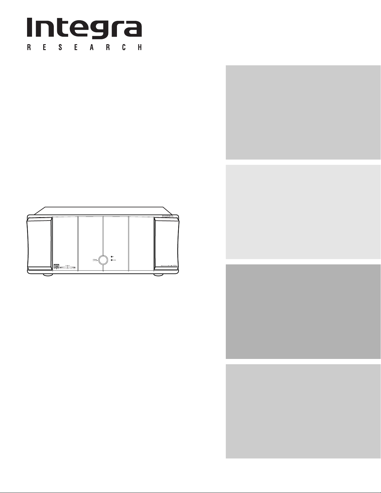
Seven Channel Amplifier
RDA-7
Instruction Manual
Contents
Before using
Operations
Thank you for purchasing the Integra
RESEARCH Seven Channel Amplifier.
Please read this manual thoroughly before
making connections and plugging in the unit.
Following the instructions in this manual will
enable you to obtain optimum performance
and listening enjoyment from your new Seven
Channel Amplifier. Please retain this manual for
future reference.
Connections
Appendix

WARNING:
PORTABLE CART WARNING
S3125A
TO REDUCE THE RISK OF FIRE OR ELECTRIC SHOCK, DO NOT EXPOSE THIS APPLIANCE TO RAIN OR MOISTURE.
CAUTION:
TO REDUCE THE RISK OF ELECTRIC SHOCK, DO NOT REMOVE COVER (OR BACK).
NO USERSERVICEABLE PARTS INSIDE. REFER SERVICING TO QUALIFIED SERVICE PERSONNEL.
CAUTION:
RISK OF FIRE-REPLACE FUSE AS MARKED
ATTENTION:
RISK DE D'INCEDIEREMPLASER PAR UN FUSIBLE INDIQUE
Important Safety Instructions
The important safety instruction shall include
where applicable, the following information and
warnings.
1. Read these instructions.
2. Keep these instructions.
3. Heed all warnings.
4. Follow all instructions.
5. Do not use this apparatus near water.
6. Clean only with dry cloth.
7. Do not block any ventilation openings. Install in
accordance with the manufacture’s instructions.
8. Do not install near any heat sources such as
radiators, heat registers, stoves, or other
apparatus (including amplifiers) that produce
heat.
9. Do not defeat the safety purpose of the
polarized or grounding-type plug. A polarized
plug has two blades with one wider than the
other. A grounding type plug has two blades
and a third grounding prong. The wide blade or
the third prong are provided for your safety. If
the provided plug does not fit into your outlet,
consult an electrician for replacement of the
obsolete outlet.
WARNING
RISK OF ELECTRIC SHOCK
DO NOT OPEN
AVIS
RISQUE DE CHOC ELECTRIQUE
OUVRIR
NE PAS
_A _
T15A
250V
V
The lightning flash with arrowhead symbol, within an equilateral triangle, is intended to alert
the user to the presence of uninsulated “dangerous voltage” within the product’s enclosure
that may be of sufficient magnitude to constitute a risk of electric shock to persons.
The exclamation point within an equilateral triangle is intended to alert the user to the
presence of important operating and maintenance (servicing) instructions in the literature
accompanying the appliance.
The fuse symbol, within an equilateral triangle, is intended to alert the user to always replace the fuse
with a fuse of the same type. The “T” in T15A refers to “time lag,” and the “15A” refers to a current
rating of 15 amperes.
10.Protect the power cord from being walked on or
pinched particularly at plugs, convenience
receptacles, and the point where they exit from
the apparatus.
11.Only use attachments/accessories specified by
the manufacturer.
12.Use only with the cart, stand, tripod, bracket, or
table specified by the
manufacturer, or sold
with the apparatus.
When a cart is used, use
caution when moving
the cart/apparatus
combination to avoid
injury from tip-over.
13.Unplug this apparatus during lightning storms or
when unused for long periods of time.
14.Refer all servicing to qualified service
personnel. Servicing is required when the
apparatus has been damaged in any way,
such as power-supply cord or plug is damaged,
liquid has been spilled or objects have fallen
into the apparatus, the apparatus has been
exposed to rain or moisture, does not operate
normally, or has been dropped.
2
Important Safety Instructions
Declaration of Conformity
We,
ONKYO EUROPE
ELECTRONICS GmbH
INDUSTRIESTRASSE 20
82110 GERMERING,
GERMANY
GERMERING, GERMANY
ONKYO EUROPE ELECTRONICS GmbH
A.HORIUCHI
declare in own responsibility, that the ONKYO product described
in this instruction manual is in compliance with the corresponding
technical standards such as EN60065, EN55013, EN55020 and
EN61000-3-2, -3-3 (or EN60555-2, -3)
For Canadian model
For models having a power cord with a polarized plug:
CAUTION: TO PREVENT ELECTRIC SHOCK, MATCH WIDE
BLADE OF PLUG TO WIDE SLOT, FULLY INSERT.
Modele pour les Canadien
Sur les modèles dont la fiche est polarisée:
ATTENTION: POUR ÉVITER LES CHOCS ÉLECTRIQUES,
INTRODUIRE LA LAME LA PLUS LARGE DE LA FICHE DANS
LA BORNE CORRESPONDANTE DE LA PRISE ET POUSSER
JUSQU’AU FOND.
For British model
Replacement and mounting of an AC plug on the
power supply cord of this unit should be performed
only by qualified service personnel.
IMPORTANT
The wires in the mains lead are coloured in
accordance with the following code:
Green-and-Yellow : earth
Blue : neutral
Brown : live
As the colours of the wires in the mains lead of this
apparatus may not correspond with the coloured
markings identifying the terminals in your plug,
proceed as follows:
The wire which is coloured green and yellow must
be connected to the terminal in the plug which is
marked with the letter E or by the earth symbol ,
or coloured green or green and yellow.
The wire which is coloured blue must be
connected to the terminal which is marked with
the letter N or coloured black.
The wire which is coloured brown must be
connected to the terminal which is marked with
the letter L or coloured red.
IMPORTANT
A 13 ampere fuse is fitted in this plug. Should the
fuse need to be replaced, please ensure that the
replacement fuse has a rating of 13 amperes and
that it is approved by ASTA or BSI to BS1362. Check
for the ASTA mark or the BSI mark on the body of
the fuse.
IF THE FITTED MOULDED PLUG IS UNSUITABLE FOR
THE SOCKET OUTLET IN YOUR HOME THEN THE FUSE
SHOULD BE REMOVED AND THE PLUG CUT OFF AND
DISPOSED OF SAFELY. THERE IS A DANGER OF
SEVERE ELECTRICAL SHOCK IF THE CUT OFF PLUG IS
INSERTED INTO ANY 13 AMPERE SOCKET.
If in any doubt, please consult a qualified
electrician.
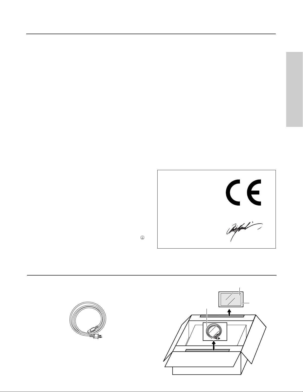
Supplied accessories
Check that the following accessories are supplied with the RDA-7.
Power cord × 1
The power cord may differ
depending on the region.
Power cord
Instruction Manual
RDA-7
Inner carton
Poly bag
3
Features
Contents
■ RDA-7 was designed by Balanced Audio
Technology in USA. They are known for
producing superbly engineered, meticulously
crafted products that recreate music with
unmatched fidelity and accuracy.
■ THX® Ultra Certified
■ THX Surround EX™ Capable (7 Channels)
■ Low-Negative Feedback Design for Optimum
Signal-to-Noise Performance and Superior
Dynamic Contrasts (Both Large and Small)
■ Balanced XLR Inputs for Better Frequency
Response, Dynamic Range and Stability on long
Cable Rune
■ High-Current Driver Stage for the Finest
Performance from Any Loudspeaker
■ 3 Gain Stages to Minimize Signal Coloration and
Improve the Amplifier’s Sonic Neutrality
■ Wide Range Design to Ensure the Full Sonic
Benefits from the Latest High-Resolution Source
Before using
Important Safeguards ............................................. 2
Features.................................................................... 4
Contents ................................................................... 4
Unpacking and storing
the packing materials ............................................ 5
Precautions .............................................................. 6
Installation ............................................................... 7
Operations
Quick operation guide ........................................... 8
Front panel facilities ............................................... 9
Connections
Rear panel facilities and connections ............... 10
Connecting speakers ........................................... 12
Connecting to the RDC-7 ..................................... 13
Appendix
■ Massive, High-Quality, Dual 1kVA toroidal
Transformers
■ Over 1000 Watts of Total Output Power (150W ×
7Ch)
* is Trademark of Balanced Audio
Technology.
* Lucasfilm, THX, THX Ultra and THX Surround EX are
registered trademarks of Lucasfilm LTD.
THX Ultra
Before any home theatre component can be THX Ultra
certified, it must pass a rigorous series of quality and
performance tests. Only then can a product feature the
THX Ultra logo, which is your guarantee that the Home
Theatre products you purchase will give you superb
performance for many years to come. THX Ultra
requirements define hundreds of parameters, including
power amplifier performance, and pre-amplifier
performance and operation for both digital and analog
domains. THX Ultra receivers also features proprietary THX
technologies which accurately translate film soundtracks
for home theater playback.
Cautions regarding humming noise ................... 14
Troubleshooting guide.......................................... 15
Specifications ........................................................ 15
4
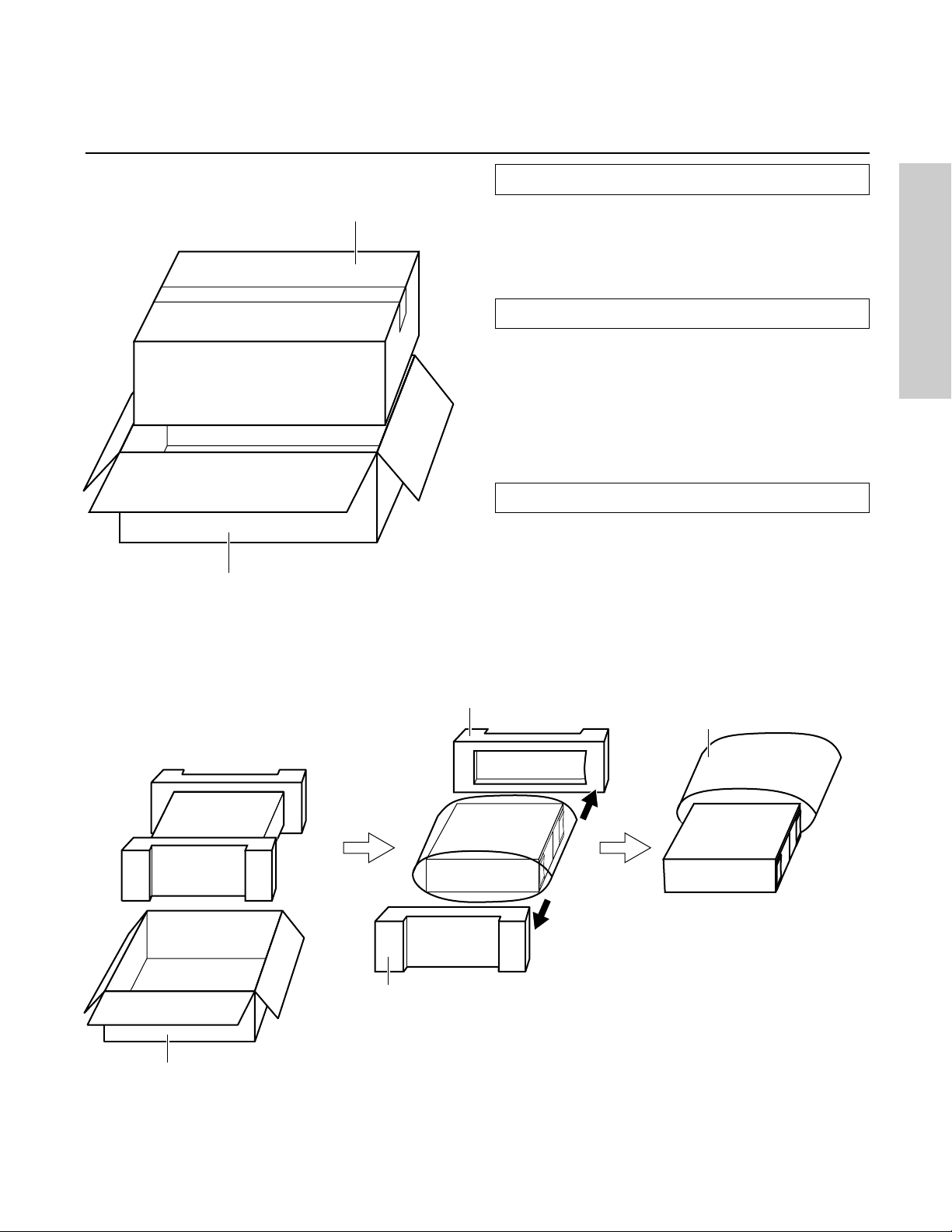
Unpacking and storing the packing
materials
Unpacking
Outer carton
(Shipping carton)
Inner carton
When unpacking the RDA-7, be sure to remove all
accessories from the cardboard box and then check
that all are included and none are missing.
Removing the RDA-7
After removing the RDA-7, carefully inspect it to make
sure that it has not been damaged during the shipping
processes. If damaged, contact an Onkyo service
station or representative immediately. Also, take down
the name of the carrier in case it is necessary to obtain
compensation from the carrier service.
Storing the packing materials
After unpacking, store the cardboard box and packing
materials in a safe place; do not throw them away. If
you are to transport the RDA-7 at a later date, you will
need this cardboard box and the packing materials.
The RDA-7 is very heavy and may become damaged if
it is transported in a different box.
Inner carton
Pad
Poly bag
Pad
5

Precautions
Before using the RDA-7 power amplifier, be sure to
read the page above entitled Important Safeguards
and this page of precautions.
Power cord
The RDA-7 comes with a three-pronged power cord that
contains a grounding wire. To help prevent electrical
shocks, always insert all three prongs when plugging in
the power cord. If the plug of the power cord is not
properly plugged in all the way, it may lead to an
electrical shock.
Be sure to only use wall sockets that properly fit the plug
of the power cord. If the socket does not match the
plug of the power cord, you will need to prepare an
adapter. Always use an adapter that is properly
certified for this application.
WARNING:
THIS APPARATUS MUST BE EARTHED.
AC fuse
Never bypass the fuses when connecting components
or the RDA-7.
Whenever performing maintenance on the RDA-7, any
of its supplied accessories, or any device connected to
it, do not use solvents or cleaners of any kind that are
inflammable or combustible.
Other
Below is a list of actions that you should never perform.
• Never perform a “thumb test” (checking whether
current is reaching the lead wire on the hot end of
the input by touching it with your fingers) on the ends
of the input jacks or input cables. Doing so may
damage the speakers.
• Never short-circuit an output terminal.
• Never remove the cover of the RDA-7. Furthermore,
never operate the RDA-7 when the cover is removed
for any reason.
• Never operate the RDA-7 in environments with
explosive gases or materials.
• Do not install the RDA-7 in a location within the reach
of small children.
Lightning storms
Speakers
Connected speakers should have an impedance of 4
ohms or greater. If speakers with an impedance of less
than 4 ohms are connected, it may damage the RDA-7.
Ventilation
The RDA-7 is a high-power amplifier, so the internal
temperature of the device rises to a high temperature.
Therefore, place the RDA-7 in a location where the flow
of air around the device is good. Also, do not place
objects or other system components on top of the RDA7 or block the ventilation holes in any way. This may
cause the internal temperature to rise and lead to a
malfunction or damage the internal components.
Care
From time to time you should wipe the front and rear
panels and the cabinet with a soft sloth. For heavier dirt,
dampen a soft cloth in a weak solution of mild
detergent and water, wring it out dry, and wipe off the
dirt. Following this, dry immediately with a clean cloth.
Do not use rough material, thinners, alcohol or other
Chemical solvents or cloths since these could damage
the finish or remove the panel lettering.
6
Never touch the power cord or plug of the RDA-7 during
a lightning storm.
Power
WARNING:
BEFORE PLUGGING IN THE UNIT FOR THE FIRST TIME, READ
THE FOLLOWING SECTION CAREFULY.
The voltage of the available power supply differs
according to country or region. Be sure that the power
supply voltage of the area where this unit will be used
meets the required voltage (e.g., AC 120V, 60Hz)
Warranty Claim
You can find the serial number on the rear panel of this
unit. In case of warranty claim, please report this
number.
Recording Copyright
Recording of copyrighted material for other than
personal use is illegal without permission of the copyright
holder.

Installation
Preventing excessive rise in the internal temperature
of the RDA-7 is vital to the long operational life of the
equipment. This will also help prevent trouble at the
RDA-7 from damaging other connected
components. Therefore, it is important to choose a
location with excellent ventilation for installation.
Ventilation
During normal household use of the RDA-7, only its
internal heatsink becomes warm. However, if used with
low impedance speakers at high volume levels, the
internal temperature level will rise higher than usual.
These high internal temperatures may cause damage
to the internal components.
To prevent damage from occurring due to high internal
temperatures, it is vital to have proper ventilation and
passage of air to carry out the heat and keep the
internal temperature within acceptable ranges.
Caution
• Do not place the RDA-7 inside cabinets or closets
where there is poor passage of air and ventilation.
• Do not place the RDA-7 near external heat sources
such as heaters or hot air ducts.
• Do not place other components or object on top of
the RDA-7.
• The cover of the RDA-7 contains ventilation holes to
allow the passage of air. Do not cover or block these
holes in any way.
If you are planning to place it within a cabinet, either
open holes in the rear panel of the cabinet to improve
ventilation or use a fan to force air circulation.
As a general rule, if during idling the cover is too hot to
touch, than ventilation needs to be improved.
Installation location and space
The RDA-7 is an extremely heavy piece of equipment.
Make sure that the floor or cabinet or rack where it will
be located is strong enough to support its weight.
You will also need to leave enough space behind the
RDA-7 to allow room for the power cord and other
cables for connecting system components. A minimum
of three inches is required behind the RDA-7 to allow
room for the cables and cords without excessively
bending them.
7

Quick operation guide
Here is a quick guide for those who want to listen to
music or view their favorite movies as soon as
possible. Connections and operations are explained
briefly here for the purpose of just getting you
started.
For those of you who want to operate the RDA-7
right away, follow the guide below. However, this
instruction manual contains a great deal of other
information that you should know for the proper
operation of the RDA-7 and for a more pleasurable
experience with the RDA-7. Be sure to read the rest
of this manual as well after reading this quick guide.
The procedures given below assume that the other
system components are already connected. (For
example, that the source components are already
connected to the control amplifier or pre-amplifier.)
For perfect sound reproduction
This unit uses no relay in its output circuit for perfect
quality sound reproduction. This, however, may also
result in the reproduction of noise-prone signals from
each channel until the internal circuitry becomes
stabilized. To prevent this, you should normally preheat
the unit for more than 15 minutes until the sound quality
becomes stabilized. We recommend that, after turning
the power on, you leave the unit for more than 30
minutes and enjoy playing your favorite music or movies
when the internal circuitry becomes stabilized.
1. Lower the volume at the pre-amplifier.
Lower the volume of the pre-amplifier to the minimum so
that when the RDA-7 is turned on, you do not hear loud
unwanted sounds.
2. Connect the speakers to the RDA-7.
Connect the speakers to the RDA-7 using the proper
speaker cables. Be sure not to mix the left and right
channels and positive (+) and negative (-) polarities. If
the connections are mistaken, the correct orientation
will not be obtained and left-right phasing will be
reversed.
3. Select balanced input (XLR) or unbalanced
input (RCA) with the INPUT SELECT switch.
The RDA-7 possesses a balanced input (XLR) and
unbalanced input (RCA) for each channel and the
switch for the two is located between the two input
terminals. Select the proper input type depending on
the functionality of the connected cables and preamplifier.
Note:
Do not change the INPUT SELECT switch setting when the
RDA-7 is turned on.
4. Connect the pre-amplifier to the RDA-7.
After selecting the correct input type in step 3 above,
connect the output from the pre-amplifier to the
corresponding input terminal on the RDA-7.
Note:
Do not connect anything to the other input jack.
5. Connect the supplied power cord to the RDA-7
and to the wall power outlet.
Be sure to properly plug the power cord all the way in.
6. Press the POWER switch.
When you press the Power switch, the On indicator lights
blue. If a cable is connected to the 12V TRIGGER IN
terminal, the On indicator lights blue when there is a
signal and the Standby indicator lights red when there is
no signal.
7. Slowly increase the pre-amplifier volume.
Note:
After the RDA-7 is turned on, it takes approximately 9
seconds before the output stabilizes. During this time, do
not turn up the volume.
Now all that remains is to control the pre-amplifier and
the other connected system components and enjoy
your music or movies.
8

Front panel facilities
Power On / Off
Pressing this switch connects the RDA-7 to the main
Power outlet and the On indicator lights blue. Sound will
be heard after approximately 9 seconds. If you want to
operate the RDA-7 using a 12-volt trigger, connect to
the 12V TRIGGER terminal of a control amplifier or preamplifier and leave the Power switch of the RDA-7 set to
On.
For example, to control the RDA-7 while it is connected
to the RDC-7 AC controller, connect the 12V TRIGGER A
jack of the RDC-7 to the 12V TRIGGER IN jack of the RDA7 with a 3.5-mm (1/8-inch) mini-jack cable.
If a plug is connected to the 12V TRIGGER IN jack:
The signal reaches the 12V TRIGGER, the On indicator
lights blue. When there is no signal at the 12V TRIGGER,
the Standby indicator lights red.
Power
On
O f f
On
Standby
Seven Channel Amplifier
RDA-7
On/Standby
The RDA-7 is equipped with two indicators to display its
status. If both indicators are off, then the main Power
switch on the front panel is turned off. If the Power switch
is turned on, then one of these indicators will be lit.
On: Lights blue when Power is supplied from the AC
mains Power supply.
Standby: Lights red when no signal is input from the
12V TRIGGER IN terminal and the RDA-7 is in the
Standby state.
Note:
If the Power switch is pressed and neither indicator lights,
check that the Power cord is properly connected and
that a fuse has not blown. If the indictors still do not light,
turn off the RDA-7, disconnect the Power cord, and
contact an Onkyo service station or representative.
If the On indicator lights blue and the Standby indicator
flashes red, the protection circuitry of the RDA-7 has
activated. The protection circuitry activates if a
problem such as a speaker cord shorting or the
temperature of the RDA-7 rising excessively occurs. Turn
off the RDA-7, remove the cause of the problem, and
then turn the RDA-7 back on. If the problem is still not
solved, turn off the RDA-7, disconnect the power cord,
and contact an Onkyo service station or representative.
9

Rear panel facilities and connections
Caution
• Do not connect the Power cord until you have finished all other connections.
• Read the instructions that came with the other components you are connecting.
• Do not make connections to input or output jacks while the RDA-7 is turned on (Power
• Always turn the volume of the pre-amplifier down before turning on the RDA-7.
on).
SURROUND BACK
RIGHT
INPUT
SELECT
OUTPUT
SURROUND
RIGHT
OUTPUT
INPUT
SELECT
RIGHT
OUTPUT
INPUT
SELECT
FUSE
Precaution for connection
This unit comprises 7 independent power amplifiers,
each being capable of reproducing the same quality
sound through its channel. Note that you should
connect an input source and a speaker to each
channel in use. For channels that are not in use, we
recommend that you do not connect any input source
or speaker.
Balanced Input (XLR terminal)
Connect controllers or pre-amplifiers with balanced
outputs for high-quality sound.
CENTER LEFT
INPUT
SELECT
OUTPUT
SPEAKER IMPEDANCE
4 OHMS MIN. PER EACH
SPEAKER TERMINAL
AC INLET
OUTPUT
INPUT
SELECT
12V TRIGGER
IN OUT
SURROUND
LEFT
OUTPUT
INPUT
SELECT
SURROUND BACK
LEFT
INPUT
SELECT
OUTPUT
SEVEN CHANNEL AMPLIFIER
MODEL NO. RDA-7
2. Disconnecting the input terminal
Pull out the connection cord while holding down the lever.
Push
Note:
• When using this balanced connection for a specific
channel between the pre-amplifier and RDA-7, set
the INPUT SELECT switch to the XLR input side to select
balanced input. Next, use high-quality cables and
connect the balanced output from the pre-amplifier
to the corresponding balanced input on the RDA-7.
• Do not connect anything to the RCA-type audio
input jack.
2. non-inverting (+)
12
3
1. GND
3. inverting (-)
Connector ground terminal: Chassis grounded
The pin assignments for this terminal are given above.
This pin assignment conforms to the standard adopted
by the Audio Engineering Society. Refer to the
instruction manual supplied with the pre-amplifier and
verify that its output terminal is compatible with the pin
assignments for this terminal. If it does not, wire it so that
the output pins connect with the proper input pins.
Input terminal
1. Connecting the input terminal
Match the pins and insert the terminal until you hear a
“click.” Ensure that it is secure by gently pulling it.
10
Unbalanced Input (single end RCA input)
Connect controllers or pre-amplifiers with single-ended
outputs for high-quality sound.
Note:
• When using this single-ended connection for a
specific channel between the pre-amplifier and
RDA-7, set the INPUT SELECT switch to the RCA input
side to select single-ended input. Next, use highquality cables and connect the single-ended output
from the pre-amplifier to the corresponding singleended input on the RDA-7.
• Do not connect anything to the balanced input jack.
INPUT SELECT /
This switch is located between the balanced input and
single-ended RCA input for each channel. Use this
switch to select the input type for its channel.
Note:
• Do not change the INPUT SELECT switch setting when
the RDA-7 is turned on.

Rear panel facilities and connections
• Make sure that connections have been made only
to the inputs selected with the INPUT SELECT switches
and nothing is connected to the other ones.
+ OUTPUT –
(Speaker output and binding post)
The RDA-7 is equipped with high-current binding posts
for use at output terminals to the speaker system. To
obtain the best in sound quality from the RDA-7, we
recommend the use of high-quality speaker cables.
For each channel, connect the negative (or black)
output post to the negative (or black) input terminal of
the speaker and the positive (or red) output post to the
positive (or red) input terminal of the speaker.
Make the connections following the procedure given
below.
1.
Strip away 15 mm (5/8 inch) of wire insulation.
2. Twist wire ends very tight.
3. Unscrew
1
(5/8 inch)
2
15 mm
4. Insert wire
5. Screw
34 5
Warning
Before replacing the fuse or making any electrical
connections, always turn off the Power and disconnect
the Power cord.
12V TRIGGER IN/OUT
Connect the 12V TRIGGER IN jack to control amplifiers
that have a 12V TRIGGER output jack, such as the RDC-
7. This jacks works on between 5 to 12 volts DC. With the
Power switch of the RDA-7 set to On, you can switch the
RDA-7 between the on and Standby states with
operations at the control amplifier.
If you want another component to be activated by
turning on and off the control amplifier connected to
the 12V TRIGGER IN jack of the RDA-7, then connect the
12V TRIGGER input jack of that component to the 12V
TRIGGER OUT jack of the RDA-7. In this state, even if the
RDA-7 is turned off, the signal from the control amplifier
passes through the RDA-7 and goes out the 12V
TRIGGER OUT jack. Daisy chaining is also possible using
these jacks.
Use φ3.5-mm (1/8-inch) monaural-type mini-jack
connectors. The tip polarity of the connectors are as
shown below.
5-12 volts,
positive tip
polarity
Be sure to read “Phasing your speaker system” and
“Speaker ratings” on the following page.
Caution
• Do not connect any devices other than speakers to
these terminals. Also, never short-circuit the output
from these terminals.
• Be sure not to mistake the positive and negative
outputs or the left and right speakers. Doing so will
result in an unnatural sound space.
• Only connect speakers with an impedance of 4
ohms or greater. If a speaker with an impedance of
less than 4 ohms is connected, it may damage the
RDA-7.
• Do not connect more than one speaker cable to
one output terminal. Doing may damage the RDA-7.
Fuse
The RDA-7 uses a 250V AC slow-blow (time lag) main
fuse. To replace the fuse, insert a coin or similar object
into the groove, turn it to the left, and remove the fuse.
Replace only with the same type and same rating. The
correct fuse rating will differ depending on the voltage
of your set as given here.
120V:T15A/250V
220V/230V/240V:T10A/250V
AC INLET
Plug the supplied Power cord into this AC INLET and then
into the Power outlet on the wall,
AC INLET
Power cord (supplied)
To an AC wall outlet
• Do not use a Power cord other than the one supplied
with the RDA-7. The Power cord supplied is designed
for use with the RDA-7 and should not be used with
any other device.
• Never have the Power cord disconnected from the
RDA-7 while the other end is plugged into the wall
outlet. Doing so may cause an electric shock. Always
connect by plugging into the wall outlet last and
disconnect by unplugging from the wall outlet first.
Ground
If connecting the unit to another equipment causes
noise such as a hum, you may improve the reproduced
sound quality by connecting this terminal to the
grounding terminal of the connected equipment with a
lead wire.
11

Connecting speakers
Before connecting the speakers, place them correctly by consulting the instruction manuals that came with them.
Also, read
For surround playback, the configuration and placement of your speakers are very important.
on page 11.
Phasing your speaker system
If the speakers are not correctly connected, the phasing
may be reversed. The result is an audio output with a
strange feeling and indistinct positioning of the sound
source.
To obtain an accurate bass response, all channels must
be connected in-phase. When the tone of a single note
is output, if the speakers are in-phase, the speakers will
vibrate in unison. If the speakers are properly connected
in-phase, then the positioning (of the instrument, singer,
etc.) becomes clear. And if they are out of phase, then
the positioning becomes unclear for a sound space with
a strange feeling.
If this is the case, first check if the speaker cables are
connected properly. The cables can usually be told
apart by the colors, by different markings, or by colored
lines on the cables. Use these marking to make sure that
for each channel the red binding posts (+) on the RDA-7
are connected to the (+) terminals on the speakers and
the black binding posts (–) on the RDA-7 are connected
to the (–) terminals on the speakers.
Speaker ratings
In actuality, you can connect any type of speaker to the
RDA-7 and it will operate. The RDA-7 can operate lowimpedance speakers with Power levels that exceed
optimum levels with no problem. With many of the
speakers that are nominally rated with an impedance
of 4 ohms, their impedance may lower down to 2 ohms
within a specific frequency range. You should not
experience any problems at these low impedances
unless you demand excessively high volume levels.
Since the output performance of the RDA-7 is extremely
high, it is vital that the maximum ratings for the input
Power of the speaker system be checked. To avoid
damage to the speakers, the Power ratings for the
speakers must be equal to or greater than the output
Power rating (4 ohms) of the RDA-7 for the
corresponding impedance.
Caution
We will not be held responsible for any damage that
may occur to your speaker systems or other
components that result from the use of a speaker system
with ratings that are lower than those of the RDA-7.
• When you are using only
one speaker or when you
wish to listen to monaural
(mono) sound, a single
speaker should never be
connected in parallel to
both the right and leftchannel terminals
simultaneously.
NO!
+– –+ +– – +
RL RL
• To prevent damage to
circuitry, never shortcircuit the positive (+)
and negative (-)
speaker wire.
SURROUND BACK
RIGHT
INPUT
SELECT
OUTPUT
Surround
Back Right
Speaker
SURROUND
RIGHT
INPUT
SELECT
OUTPUT
Surround
Right
Speaker
RIGHT
INPUT
SELECT
OUTPUT
Front
Right
Speaker
CENTER LEFT
INPUT
SELECT
OUTPUT
SPEAKER IMPEDANCE
4 OHMS MIN. PER EACH
SPEAKER TERMINAL
AC INLET
FUSE
Center
Speaker
INPUT
SELECT
OUTPUT
12V TRIGGER
IN OUT
Front
Left
Speaker
SURROUND
LEFT
INPUT
SELECT
OUTPUT
Surround
Left
Speaker
SURROUND BACK
LEFT
INPUT
SELECT
OUTPUT
SEVEN CHANNEL AMPLIFIER
MODEL NO.
Surround
Back Left
Speaker
RDA-7
12

Connecting to the RDC-7
Since many users will purchase the RDA-7 together with the RDC-7, here is an explanation of how to connect the
RDA-7 to the RDC-7.
Balanced input/output connection
Note:
When using the
balanced inputs, do
not connect anything
to the RCA inputs.
RIGHT CENTER SUBWOOFER
SURROUND
RIGHT
LEFT
SURROUND
LEFT
PRE OUT
SURROUND BACK
RIGHT
SURROUND BACK
LEFT
RDC-7
XLR type
At the RDC-7
Balanced cable
SURROUND BACK
RIGHT
INPUT
SELECT
OUTPUT
SURROUND
RIGHT
OUTPUT
INPUT
SELECT
OUTPUT
RIGHT
INPUT
SELECT
CENTER LEFT
INPUT
SELECT
OUTPUT
SPEAKER IMPEDANCE
4 OHMS MIN. PER EACH
SPEAKER TERMINAL
AC INLET
FUSE
OUTPUT
INPUT
SELECT
12V TRIGGER
IN OUT
SURROUND
LEFT
OUTPUT
Connect to the RDC-7 12V TRIGGER A terminal
(φ3.5-mm (1/8-inch) mini-jack)
Unbalanced input/output connection RCA type cable
Note:
When using the RCA
inputs, do not connect
anything to the
balanced inputs.
1
FRONT
2
SURR
SURR
BACK
R
PRE
L
C
SUBWOOFER
OUT
1
2
1
1
2
2
INPUT
SELECT
RDC-7
SURROUND BACK
LEFT
INPUT
SELECT
OUTPUT
SEVEN CHANNEL AMPLIFIER
MODEL NO.
RDA-7
At the RDA-7
Push the INPUT SELECT switch
upward
RDA-7
Improper connection
Inserted completely
SURROUND BACK
RIGHT
INPUT
SELECT
OUTPUT
SURROUND
RIGHT
OUTPUT
INPUT
SELECT
OUTPUT
RIGHT
INPUT
SELECT
CENTER LEFT
INPUT
SELECT
OUTPUT
SPEAKER IMPEDANCE
4 OHMS MIN. PER EACH
SPEAKER TERMINAL
AC INLET
FUSE
OUTPUT
INPUT
SELECT
12V TRIGGER
IN OUT
SURROUND
LEFT
OUTPUT
INPUT
SELECT
SURROUND BACK
LEFT
INPUT
SELECT
OUTPUT
SEVEN CHANNEL AMPLIFIER
MODEL NO.
RDA-7
RDA-7
Connect to the RDC-7 12V TRIGGER A terminal
(φ3.5-mm (1/8-inch) mini-jack)
Push the INPUT SELECT switch
downward
13

Cautions regarding humming noise
If humming is heard even when the volume is turned
down or the RDA-7 is turned off, then a "ground loop"
may be occurring. A ground loop is a potential
difference in the grounding of two or more
electrically connected components. This potential
difference creates multiple current routes when
there should only be one. This potential difference
results in a hum noise and at times it can be just a low
level noise. With the increased sophistication of
home theaters, the chance of grounding loops
occurring has greatly increased. If humming occurs,
before considering it due to faulty equipment, read
the following information listed to the right.
1. Your cable television system wiring may be
causing the hum.
To determine whether the cable television is the cause
of the hum, disconnect the cable television cable
(round 75-ohm cable) or the first component that the
cable is connected to (the set-top box or VCR). If the
humming stops, connect a commercially-available 75ohm ground loop isolator before reconnecting the
system. If the humming still continues, read 2, 3, and 4
below.
2. An input cable is causing the hum
Turn off the entire system and disconnect all input
cables. If the humming stops, reconnect the cables one
at a time to determine the faulty cable. If the hum
continues after all input cables are reconnected,
contact an Onkyo service station or representative.
3. AC ground terminal loop
An AC ground terminal loop will cause the loudest hum.
When grounding a system that uses a power cord with a
three-pronged plug, be aware of components with a
grounding terminal. If you cannot alter your home wiring
to an insulated star-shaped grounding configuration, try
an insulation transformer.
Caution
Never remove the ground terminal (the third round
terminal) from the plug of the power cord that comes
with the RDA-7. Doing so is very dangerous for it may
cause an electrical shock or even electrocution.
4. Improper grounding in your home is causing
the hum
In most cases, a water pipe is used as the ground in your
home. Make sure that the connection is strong by
checking for loose pipes or excessive corrosion. The
most certain remedy is to ground the system
independently. Drive a 1.5-m (5-foot) or longer copperplated steel grounding pole into the ground and use this
as the system ground. If you have questions regarding
this procedure consult an electrician or your local
electrical company.
If after exhausting all the possibilities given above the
humming continues, contact an Onkyo service station
or representative.
5. Both the balanced-line inputs and RCA inputs
are connected
Unconnect either set and make sure the input selector
switch is set to the correct position.
14

Troubleshooting guide
Specifications
If the RDA-7 fails to function normally, first check the
following points before contacting your INTEGRA
RESEARCH dealer. If the problem is not solved after
going through the following list, unplug the power
cord and contact your Integra/Onkyo authorized
service center.
POWER
No power.
• Power cord is not correctly plugged into AC outlet/
Inlet.
➞ Plug the power cord into the AC outlet/Inlet
properly.
• Power switch is not set to ON position.
➞ Set the power switch to ON.
Power turns on but no sound.
• Incomplete connections.
➞ Check speaker cable connections.
➞ Insert all plugs firmly into jacks.
• No input signal from preamplifier.
➞ Check for input signal from preamplifier.
• Incorrect INPUT SELECT switch setting.
➞ Set INPUT SELECT switch to correct setting.
AMPLIFIER SECTION
Number of channels: 7
Power:
150 watts per channel min. RMS at 8 ohms, 2 channels
driven from 20 Hz to 20 kHz with no more than 0.1 % total
harmonic distortion.
300 watts per channel min. RMS at 4 ohms, 2 channels
driven at 1 kHz with no more than 0.1 % total harmonic
distortion.
Frequency response @ -3 dB: 3.5 Hz - 250 kHz
Input Impedance: 47 kohm each phase
Input signal for max output power:
1.2 V
Input Sensitivity (Unbalanced):
100 mVrms
Input Sensitivity (Balanced): 200 mV
THD: 0.03 %(20 Hz to 20 kHz)
Damping Factor: 40 at 8 ohm
Power consumption
USA, Canada and some Asian model:
15 A
Other models: 10 A
Rated Speaker Impedance: 4 ohms
GENERAL
Power Supply: AC 120 V, 60 Hz
AC 230 V, 50 Hz
AC 220 V, 50/60 Hz
Dimensions (W × H × D): 450 × 195 × 596 mm
17-11/16" × 7-11/16" × 23-7/16"
Weight: 51.0 kg, 112.4 lbs.
Specifications and features are subject to change without
notice.
Power supply and voltage vary depending on the area in
which the unit is purchased.
The Standby indicator is lit.
• Protective circuitry activated.
➞ A problem such as a speaker cord shorting or the
temperature of the RDA-7 rising excessively may
have occurred. Turn power off immediately,
locate problem, and correct it.
15

Integra Research Division of
ONKYO CORPORATION
Sales & Product Planning Div. : 2-1, Nisshin-cho, Neyagawa-shi, OSAKA 572-8540, JAPAN
Tel: 072-831-8111 Fax: 072-833-5222 http://www.onkyo.co.jp/
Integra Research Division of
ONKYO U.S.A. CORPORATION
200 Williams Drive, Ramsey, N.J. 07446, U.S.A.
Tel: 201-825-7950 Fax: 201-825-8150 E-mail: research@onkyousa.com
ONKYO EUROPE ELECTRONICS GmbH
Industriestrasse 20, 82110 Germering, GERMANY
Tel: 089-849-320 Fax: 089-849-3265 E-mail: info@onkyo.de
ONKYO CHINA LIMITED
Units 2102-2107, Metroplaza Tower I, 223 Hing Fong Road, Kwai Chung,
N.T., HONG KONG Tel: 852-2429-3118 Fax: 852-2428-9039
SN 29342947
D0008-1
E
 Loading...