


Operating instructions
AMBUS®Net
Software versions 1.01.xx
VD 9-905e 02.2011

2
Table of contents
1
Introduction ................................................................................................................................................ 3
1.1 Applications ........................................................................................................................................... 3
2 Components ............................................................................................................................................... 4
2.1 Housing and power supply .................................................................................................................... 4
2.2 Processor .............................................................................................................................................. 4
2.3 Interfaces .............................................................................................................................................. 4
2.4 Technical data of interfaces .................................................................................................................. 5
2.5 Memory board and serial flash .............................................................................................................. 6
2.6 Multilingual feature with HTML tags ...................................................................................................... 6
2.7 Communication and security................................................................................................................. 7
2.8 Versions ................................................................................................................................................ 8
2.9 Open architecture ................................................................................................................................. 8
3 Commissioning .......................................................................................................................................... 9
3.1 Power supply and display ..................................................................................................................... 9
3.2 Basic setting of AMBUS® Net............................................................................................................... 9
3.3 Meter list, commissioning the M-Bus and automatic meter search .................................................... 11
3.4 Network (Windows) ............................................................................................................................. 13
3.5 Communication via modem ................................................................................................................ 16
3.6 Data logger / CF card .......................................................................................................................... 19
4 Operation .................................................................................................................................................. 20
4.1 Summary of menu .............................................................................................................................. 20
4.2 Status message and general alarm .................................................................................................... 20
4.3 Reading the meter .............................................................................................................................. 21
4.4 The usage units .................................................................................................................................. 21
4.5 Monitoring the meters: the analysis usage unit ................................................................................... 23
4.6 Data logger (optional) ......................................................................................................................... 24
4.7 Meter list, manual meter readings ...................................................................................................... 26
5 Remote operation and system integration ............................................................................................ 29
5.1 SOAP: Creating a client with .Net ....................................................................................................... 29
5.2 Download protocol .............................................................................................................................. 32
6 Troubleshooting ...................................................................................................................................... 33
7 Appendix .................................................................................................................................................. 35
T
ABLE 1: SPECIFICATIONS OF HOUSING AND POWER SUPPLY .................................................................................. 4
TABLE 2: OVERVIEW OF INTERFACES ..................................................................................................................... 5
TABLE 3: COMMUNICATION AND SECURITY.............................................................................................................. 7
TABLE 4: SPECIFICATIONS FOR VERSIONS .............................................................................................................. 8
TABLE 5: SPECIFICATIONS FOR OPTIONS ................................................................................................................ 8
TABLE 6: TROUBLESHOOTING .............................................................................................................................. 34
TABLE 7: EXAMPLE OF METER PROTOCOL ............................................................................................................. 35
TABLE 8: EXAMPLE OF USAGE UNIT PROTOCOL .................................................................................................... 36
TABLE 9: EXAMPLE INSTALLATION PROTOCOL ....................................................................................................... 37

3
1 Introduction
AMBUS® Net is an integrated extension of AMBUS
®
ZS and enables intelligent M-Bus central units to be
configured, operated and monitored by M-Bus plants as complete systems with state-of-the-art technology
and customer-friendly operation.
The ¼ VGA touch screen display ensures easy-to-handle on-site operation without the need of a PC.
Because it contains a Web server, the instrument can also be remotely operated via either a direct telephone
link (analog, ISDN or GSM) or an Intranet/Internet network. It can be operated with every Java-supported
Web browser which reproduces the operating display of the instruments and allows protocol files to be downloaded (optional).
Existing plants can be updated very simply or else expanded as required, since AMBUS
®
Net is totally com-
patible with the earlier AMBUS
®
FA system and can also be updated to become an AMBUS® M-Bus central
device.
Features
• M-Bus central device with integrated Web server
• Capacity for up to 120 or 250 M-Bus meters
• 5.7“ LCD touch screen and plain text in various languages
• Data logger for optional plug-in data memory
• 10 MB Ethernet interface via RJ-45
• For integrating telephone modems (PSTN, ISDN, GSM) with RJ-45 / Antenna (optional)
• RS232 and RS485 interface
• 2 relay contacts for error handling and communication control
• Protocols: TCP/IP, ARP, ICMP, HTTP, HTML, PPP, LCP, IPCP, PAP, SOAP/XML, WSDL
1.1 Applications
The fields of applications of the AMBUS® Net range from analytical building management for invoicing services to facility management and domestic systems. It can be installed wherever a simple and cost-effective
solution is required for on-site operation or remote monitoring.
AMBUS
®
Net is an Internet-compatible M-Bus central device with state-of-the-art technology for the following
applications:
AMBUS® Net as a modern remote display
AMBUS® Net supplies on-site readings from all meters connected to an M-Bus (Meter-Bus) network. For the
first time an instrument of this class is able to offer a 5.7“ LCD touch screen with an easy, self-explanatory
procedure in your own particular language.
Readings require no PC, no special reading program and no interface cable.
Using the data logger option:
The data can also be optionally recorded on a compact flash memory board for later evaluation on a PC.
AMBUS® Net as M-Bus Internet gateway
With AMBUS® Net your data is now online. The AMBUS® Net links M-Bus and Web technologies in an ideal
combination. As an M-Bus/Internet gateway, the AMBUS
®
Net supplies M-Bus data in seconds to your work-
station from meters recording water, heat, gas and electricity.
Using a standard Java Internet browser and a direct modem connection, the AMBUS
®
Net can be remotely
operated or data can be downloaded as an Excel-compatible file and later exported to a billing system.
The data is also automatically read and processed using software with a SOAP (XML) interface.

4
2 Components
2.1 Housing and power supply
AMBUS® Net is protected by a rugged, red-lacquered aluminium pressure die-cast housing for wall or control
cabinet mounting. The power supply is a 230 VAC mains voltage.
For information on installation refer to the installation instructions AMBUS
®
Net
The power supply is a 230 VAC/50 Hz mains voltage only.
An LED indicates stand-by after the instrument is switched on. As soon as AMBUS
®
Net is connected to the
power supply, the device automatically runs through a start routine for initializing all integrated modules.
Display
5.7“ LCD touch screen, grey scale
Power supply voltage
230 VAC (+10, -15 %) / 50..60 Hz
Max. power consumption
2..110 VA (depending on the number of M-Bus devices installed)
Ambient temperature
5 ... 50 °C
Housing
Cast aluminium, red lacquered
Dimensions
B x H x D = 240 x 160 x 66 mm
Weight
Approx. 3.3 kg
Ingress Protection class
IP 20
Table 1: Specifications of housing and power supply
2.2 Processor
As an "embedded controller", AMBUS® Net is a high-performance device with a 32-bit RISC controller,
25 MHz, 380 KB of flash memory and 2 MB RAM. A certified, real-time operating system monitors the correct
functioning of the unit. AMBUS
®
Net is also equipped with a real-time clock and a buffer with a button cell
battery to secure data against power failure.
2.3 Interfaces
AMBUS® Net is composed of the ZS and the Net
module.
The ZS module has an M-Bus level converter, a
power supply for the M-Bus network with (2- or 4wire) auxiliary power supply and the M-Bus repeater. It has interfaces to the M-Bus, to any higher M-Bus master, one RS232 output,
one RS485 output and 2 relay outputs.
See also the installation instructions
for AMBUS® Net
The Net module consists of the display (touch
screen), the processor for evaluating the data and
slots for an optional modem and memory board.
Each is equipped with an Ethernet, telephone and
RS232 interface.

5
Ethernet network
AMBUS® Net is an Internet-supported device and can be connected to a network (LAN, Local Area Network)
via the Ethernet RJ-45 interface. It works at a speed of 10 Mbit/s.
Two LEDs on the pc board indicate if it is linked to the network (for diagnosis and only visible when the instrument is opened):
LED
Significance
LINK
Network correctly connected
LAN
Data being transmitted
Modem
AMBUS®Net is a modular system. It may be fitted with
the following modems: PSTN modem (analog), ISDN
modem and GSM modem.
The analog and ISDN modem can be connected to a
telephone network via the RJ 45 socket. For the antenna
of the GSM modem a screw connection comes from the
housing (type FME / quasi standard of cellular phones in
vehicles).
Analog modem
ISDN modem
GSM modem
Front and rear view of the
modem: The SIM board is
located on the back in the
SIM board reader
GSM modem antenna
The enclosed adhesive antenna with approx. 3 m cab
le is
suitable for mounting in a location with good radio reception (e.g. at a window).
2.4 Technical data of interfaces
M-Bus installation
2- or 4-wire system
Meter power supply (4-wire M-Bus)
15 VAC, ± 20 %
M-Bus data transmission rate
300, 2400, 9600 Baud; combination also possible
M-Bus repeater
yes, 1 M-Bus load
Ethernet
10 MB, RJ-45
Telephone modem
PSTN V.92, RJ-45 (analog modem), 56 kBit/s
ISDN, RJ-45, 64 kBit/s
GSM (dual band 900/1800 MHz) 9.6 kBit/s
Memory board
Compact flash card type 1 with 16 MB - 2 GB storage capacity
M-Bus direct connection
RS232, RS485
Service connection
RS232
Alarm and Busy relay
Semiconductor relay, potential-free, 50 V / 100 mA AC / DC
Table 2: Overview of interfaces

6
2.5 Memory board and serial flash
CF card
AMBUS® Net with the "data logger" option can record plant and meter data at periodical intervals. This requires e CF card being used as a removable data carrier between the AMBUS
®
Net and a PC.
The size of the CF memory card determines the extent of the memory available for
AMBUS® Net.
Max. number of files on the memory card
512
File system
FAT 16
Capacity
Max. 2 GB
All logger files are stored exclusively in CSV format (Microsoft Excel / ASCII-File /
*.CSV). The semicolon (;) is thus used for column formatting and the carriage return
(CR) for a new line.
A safety lock is supplied with the "data logger" option in order to prevent the CF card
from being removed.
CF card
Serial flash
AMBUS® Net stores all plant-specific parameters on a removable data carrier, or
serial flash. This is plugged onto the pc board attached to the front of the instrument.
The housing must be opened in order to replace it.
When changing the device, this means that all settings and parameters are adopted
in the new device.
The serial flash also contains the Java driver and language information.
Serial flash
2.6 Multili ngua l feature with HTML tags
With consistent use of World Wide W eb technology, AMBUS® Net supports the simple changeover to
various operating languages located on the serial flash. This means that any change requires another
language file in the serial flash.
Example 1 : Before start-up: Changing the language is relatively easy by simply ordering a new serial
flash and replacing the old one.
Example 2 : After start-up: Changing the language is more difficult as the plant data in the serial
flash should not be lost.
Please contact Aquametro Customer Service.
The following languages are at present available (other languages on request):
• German
• French
• English

7
2.7 Communication and security
Four versions of the AMBUS®Net are available: AMBUS® Net LCD120 and AMBUS® Net LCD250 have a
touch screen and are therefore to be used when a local display and on-site operation are required.
The gateway versions AMBUS® Net 120 and AMBUS® Net 250 do not have touch screens and are therefore
to be installed in plants where remote readout and operation are required and where a more rapid network
connection is available.
Channel
PC
AMBUS
®
Net No.
Connection
Access protection
A1Point-to-point connection with modem,
safe from unauthorized access.
•
Private telephone connection
• Access code
b2PC and AMBUS®Net are connected to
the Internet. The PC is protected by a
firewall. AMBUS®Net is operated us
ing a
dedicated IP ad
dress supplied by the
Internet provider.
•
IP address not openly known
• Access code
c3As , but within an Intranet protected by a
firewall.
•
Firewall
• Protected LAN connection
• Access code
b,c
1,2,3
Access to AMBUS®Net via an Internet
portal which has the following tasks:
• Monitoring access
• Communicating with AMBUS
®
Net via
configured channels (with modem, direct IP address or VPI agent, see dotted lines)
• Carrying out application-specific func-
tions, e.g. data conversion or data-
base-specific evaluations.
•
Access protection by portal
• Access code
b3VPI*)technology also provides secure
access to an AMBUS® Net
device within a
VPI-
protected network. The portal and VPI
agent in the DMZ
**)
ensure that only a
portal server has access.
•
Access protection by portal
• VPI
• Access code
Table 3: Communication and security
*)
VPI: Virtual Private Infrastructure ensure maximum access preotetion
**)
DMZ: Demilitarised Zone
8
2.8 Versions
Four versions of the AMBUS® Net are available: AMBUS® Net LCD120 and AMBUS® Net LCD250 have a
touch screen and are therefore to be used when a local display and on-site operation are required.
The gateway versions AMBUS® Net 120 and AMBUS® Net 250 do not have touch screens and are therefore
to be installed in plants where remote readout and operation are required and where a more rapid network
connection is available.
Designation
Number
of M-Bus
units
LCD
Internet server
Ethernet RJ-45
Telephone
modem
Data logger
with CF
card
RS-232
&
RS-485
Art.
No.
AMBUS® Net LCD120
120
optional
optional
93178
AMBUS® Net LCD250
250
optional
optional
93179
AMBUS® Net 120
120
optional
optional
93180
AMBUS® Net 250
250
optional
optional
93181
Table 4: Specifications for versions
Options, accessories and services:
Designation
Description
Art.
No.
Data logger
Data logger with theft-proof and CF memory card
93182
PSTN modem (analog)
Integrated PSTN telephone modem (analog)
93183
ISDN modem
Integrated ISDN telephone modem
93184
GSM modem
Integrated GSM telephone modem
93185
CF Card
CF memory card
19879
Languages
Please state operating language when ordering. Languages available: German, French, English (others on request).
Table 5: Specifications for options
2.9 Open architecture
AMBUS® Net is based on an open architecture and is compatible with the following standards:
• HTTP Hypertext Transfer Protocol (transport medium)
• HTML Hypertext Markup Language (format)
• TCP/IP Transmission Control Protocol / Internet Protocol
• ARP Address Resolution Protocol (network command)
• PPP Point-to-Point Protocol (for communication via a modem)
• ICMP Internet Control Message Protocol (for transmitting the status of the protocols IP, TCP and
UDP between IP network nodes)
• LCP Link Control Protocol (connecting, configuring, testing and disconnecting a PPP connection)
• IPCP Internet Protocol Control Protocol (for IP-connections via PPP)
• PAP Point Authorization Protocol (authenticating method for the PPP protocol)
Communication with other applications is based on the following open standards:
• SOAP Simple Object Access Protocol (software interface with XML syntax)
• WSDL Web Services Description Language (describing the interfaces of the Web service)
9
3 Commissioning
3.1 Power supply and display
Connecting the power supply
Check that the power supply cable is connected to the correct terminals and switch on the power supply.
Refer to the installation instructions AMBUS® Net for connecting the power supply correctly
The display lights up. After 2 minutes of idle operation the background lighting is switched off. When touch-
ing the screen, backlighting is switched on again and the default page (see section 3.2) is displayed.
The operating lamp ("Power" / "Alarm") remains it.
• Installation and maintenance work may only be carried out when the device is not connected
to the power supply.
• The grounding cable must be connected to the ground terminal of the housing.
• Work on the 230 V power supply may only be carried out by authorized specialists in accord-
ance with all regulations currently in force.
• The power supply cable may only be connected to the terminals "L" and "N". Any other connections may endanger life and may also permanently damage all meters connected to the
bus system.
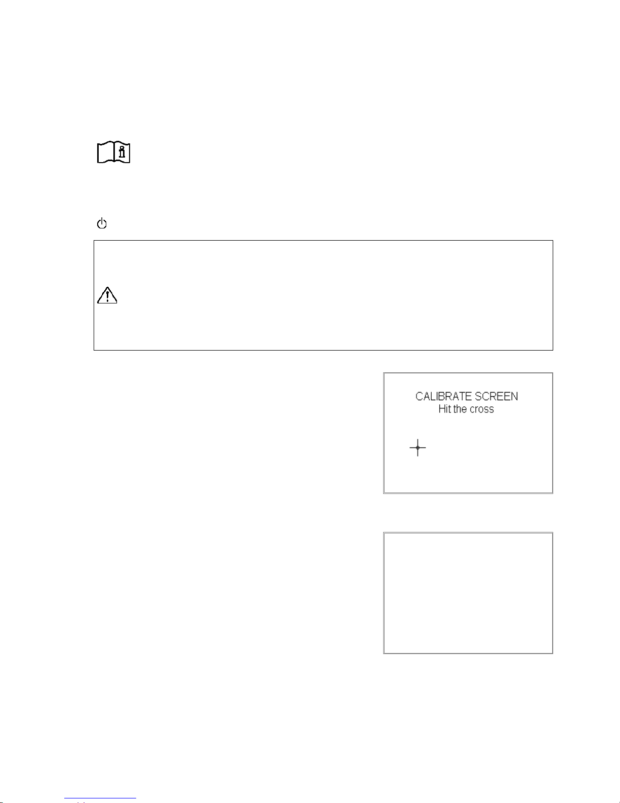
Calibrating the touch screen display
Once the device has been switched on, the IP address is first displayed then a prompt shown for approx. 10 seconds to calibrate the
display. This should only be done if operation is poor (that is, if the
sensitive fields do not align well with the displayed fields or if it is
necessary to press hard)
If calibration is necessary, then press the cross hairs with a blunt
object until the menu is shown in the default display.
3.2 Basic setting of AMBUS® Net
Default display
The menu is now in the default display. You see:
• At the bottom left, the maximum number of meters to be pro-
cessed, e.g. "AMBUS
®
Net 120"
• At the center top: the system designation (for programming see
3.2 System menu)
• At the center bottom: Status of the system (active only after
reading the connected meters)
10
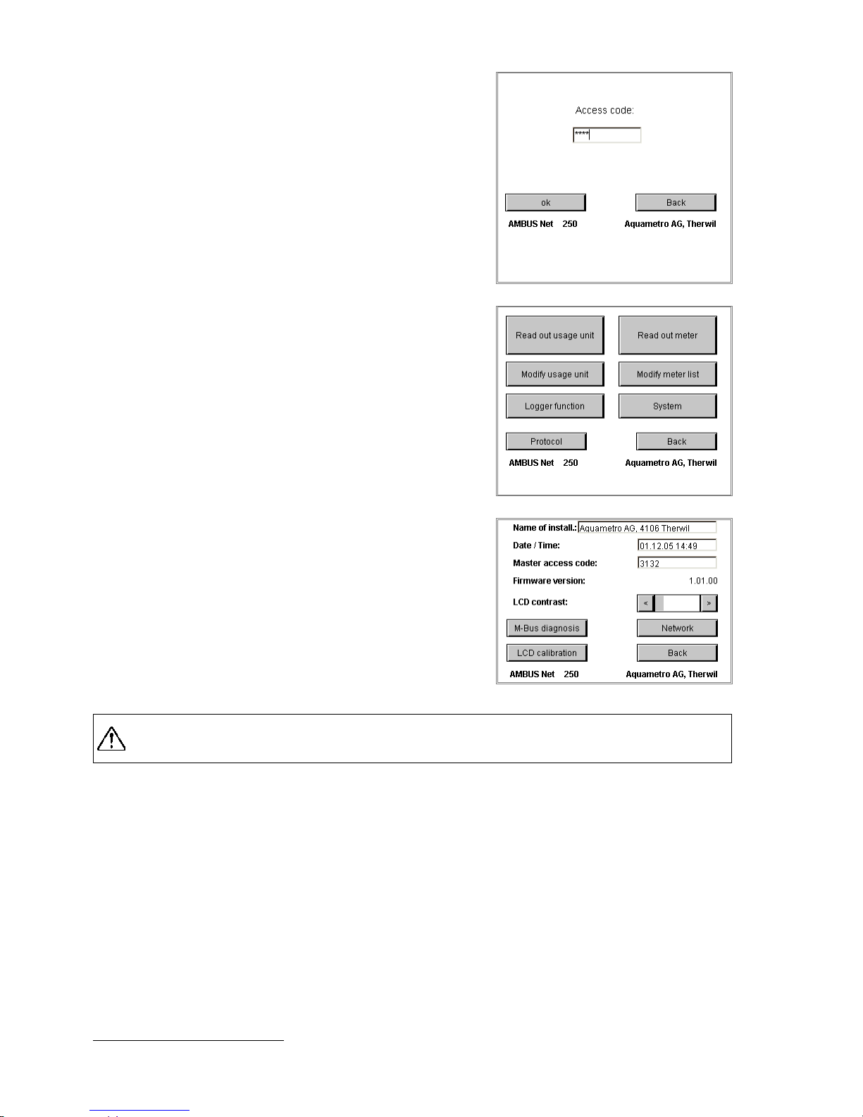
By pressing the display the following are called up:
Access code
AMBUS® Net differentiates between two access authorizations,
both of which are protected by a coded number.
1. System access code (shown on the right)
2. Usage unit access code (see sect. 4.4 The usage units)
When touching the field "Access-Code", a keyboard is displayed;
enter code “3132“(factory settings) and confirm with OK.
The main menu is displayed.
(The code must be re-entered if there is no operation after several
minutes.)
Main menu
Select "System" in the main menu for carrying out the basic settings of the device:
For other menu points see:
For read out meter / Modify meter list: see section 3.3 read
out meter
For Modify usage unit and Read out usage unit see section
4.4 The usage units
• For Logger function (option) see:
1.1 Fehler! Kein gültiges Resultat für Tabelle.
System menu
Check/correct the following basic settings:
• Name of the installation: Touch the field, a keyboard is
displayed; you can enter a name of max. 40 characters.
• Date and time: Setting the system time in the form of:
dd.mm.yy.hh.mm
• Access code: This can be a maximum of 8 characters
It is necessary to contact Aquametro Customer Service if the access code is lost!!
• Details of the current firmware version of the device
• LCD contrast
Adjust the contrast using the "<" and ">" keys so that there is sufficient contrast on the screen but
no shading.
*)
The calibration routine of the touch screen is done via the menu "LCD calibration" as described above.*)
*)
The LCD balance and contrast cannot be set over the remote control.
11
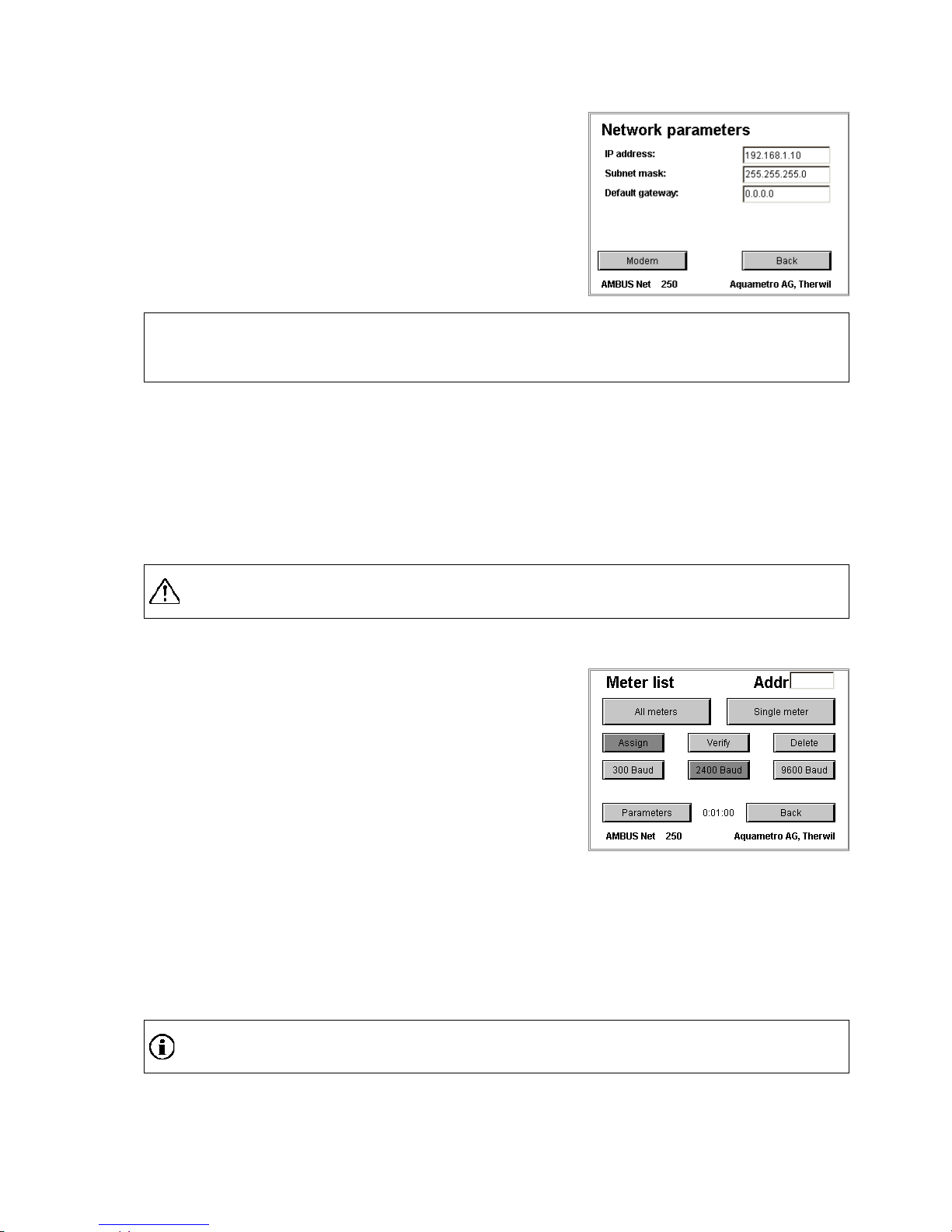
The communication parameters are checked and set via the menu "System / Network":
System / Network menu
Settings of the Ethernet interface:
• IP address, subnet mask and standard gateway are described
in greater detail in Section: 3.4 Network (Windows).
Entries are only required when using the network.
AMBUS® Net is now ready for operation!
Follow the instructions 3.3 Meter list, commissioning the M-Bus and automatic meter search.
3.3 Meter list, commissioning the M-Bus and automatic meter search
System requirements
• All M-Bus meters to be processed by AMBUS® Net must be wired up correctly according to the installa-
tion instructions AMBUS
®
Net.
• All meters must have previously been assigned a unique primary address (M-Bus EN 1434-3).
(Please refer to the operating instructions of the meters used in the system.)
• Select addresses in the range 1...250.
Ensure that the same address is not assigned to different meters otherwise no communication to
those meters will be possible!
When in the main menu select:
Modify meter list
Use the automatic meter search function in order to enter meters in
the AMBUS
®
Net as follows:
• Select Delete – All meters if meters from a previous applica-
tion have been entered incorrectly
AMBUS
®
Net indicates: “All meters deleted“
Start with the highest baud rate to automatically differentiate between meters with different baud rates:
Assign – 9600 Baud – All meters
Assign – 2400 Baud –All meters
Assign – 300 Baud –All meters
After completing a search, the AMBUS
®
Net indicates the number of meters found e.g. “15 meters detect-
ed“
AMBUS
®
Net can administer plants with mixed baud rates!
12
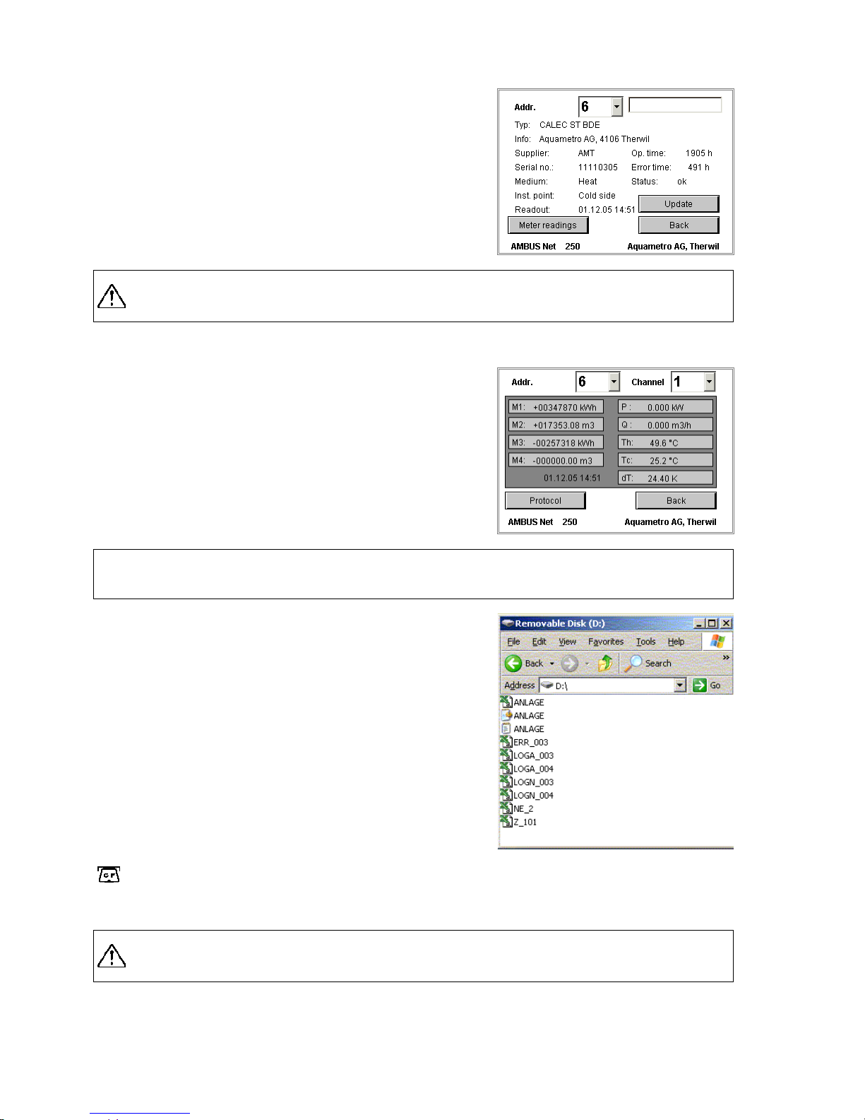
Select the meters to be read from the main menu:
Read out meter
• Select the appropriate address in the drop-down list to read out
a specific meter
• An additional text field is available for more detailed identifi-
cation. More information is given in 4.3 Reading the meter
AMBUS® Net shows meter readings from an internal m
emory, i.e. at the time of the last reading. If
the meters are to be read again, then select update.
To read out the latest meter reading, select:
Read out meter / Meter readings:
• AMBUS® Net displays a maximum of 4 meter readings and 5
actual values per device (address) and channel.
• 3 channels are available.
• Tariffs are dealt with exactly like channels.
AMBUS
®
Net can now read out and administer the asigned M-Bus meters!
Protocolling meters
A meter protocol can be stored for every meter available using the
option "data logger" and the CF card (see also 3.6 Data logger /
CF card):
After selecting e.g. the meter with the primary address 123, press
Protocol
• AMBUS
®
Net creates the file Z_123.CSV (example)
Select Protocol in the main menu (see section 3.2) to protocol the
entire plant:
• AMBUS
®
Net creates ANLAGE.CSV
The indicator lamp lights up for at least 2 seconds every
time the CF card is accessed.
CF card read out via PC
Never remove the CF card during a write operation as data could be destroyed!

13
3.4 Network ( Windows)
For configuring the network, you require the following instrument
data that are found in the system / network:
Parameter
Factory settings
Subnet mask
255.255.255.0
Standard gateway
- Mac address
In range 00 0A FF F0 00 00 ...
00 0A FF F0 FF FF
Parameter
Factory settings
If AMBUS® Net is connected to the Internet via a gateway/router, the IP address for the standard gateway is
to be set here.
The AMBUS® Net can be uniquely identified in the network via the MAC address (Media Access Control, or
LAN address). If this is required by the network administrator, the particular instrument can be read out from
the network via a PC:
1. Response of the instrument, e.g. with : ping "IP address"
→ AMBUS
®
Net must respond
2. Listing the "Address Resolution Table" with: arp –a
→ Your PC displays the IP address list with the appropriate MAC address list
after the device has been successfully connected to the network. If this is not the case, then contact Aquametro Customer Service stating the serial number.
Start the device again after reprogramming the IP address, the subnet mask or the standard
gateway address!
If the network parameters of your network are correctly set according to your system and the device restarted, the
AMBUS
®
Net can be connected to your Ethernet network using a standard RJ 45 network cable.
The following settings must be made on the PC so that the network connection functions correctly:
Network setting on the PC
All components must be located in the same network group for a
communications link via the Ethernet.
AMBUS
®
Net requires a fixed IP address.
(Example shown in Windows XP)
• Select in:
Control Panel / Network c on nections
’LAN/Local Area connection’
• Select Properties of:
’Internet Protocol (TCP / IP)’
Request a permanent IP address for the AMBUS® Net
for your network or Internet operator as
this does not support DHCP (Dynamic Host Configuration Protocol).

14
Select an IP address that is located in the same group: (The first 3
bytes must be identical.)
• ’Use the following IP address:’
• IP address: 192.168.1.1
(AMBUS® Net is delivered with 192.168.1.10 as standard)
• Subnet mask: 255.255.255.0
If the AMBUS® Net is operated in a major network, then the
system administrator will assign a fixed IP address for operating the device. In this case network settings have not to
be changed on the PC!
The PC must again be started up if network settings are made on the PC!
Java settings on the PC
Java is a programming language that permits programs to be transmitted over the Internet which are then
carried out. This presents a risk since Java functions on most network PCs are deactivated as standard.
In order for the AMBUS
®
Net remote control to function correctly, these Java applications must be made
available to the particular device.
The following settings are thus required:
• In Control Panel:
Internet Options select the label "Security"
• Select Trusted Sites:
"Sites..."
• Insert the page (IP address) for the AMBUS® Net, without
requiring server verification (https: bottom left)
http://192.168.1.10
*)
• End with OK
• Click on custom level in the previous window:
and select in "Reset custom settings“: "low"
All settings on the PC have now been completed!

15
Start your Internet browser and select:
http://192.168.1.10
*)
The AMBUS
®
Net offers two options that can be selected:
• CF Device / (Access the files on the CF card)
• start.html (remote opera tion, start page)
If AMBUS® Net has been equipped with the option: "data logger",
then select:
• CF Device /
For direct access to the logger files of your CF card.
By clicking the particular file, you can:
• either open it
• or save it to a disk
To jump back to the start menu, select:
• Parent Directory
Select
• start.html
for direct remote operation of AMBUS
®
Net.
This starts a Java application, which must be uploaded by
AMBUS
®
Net.
Be patient as the time to load the application is strongly dependent on your network capability and
performance of the PC!
AMBUS
®
Net can now be remotely operated using Ethernet!
*)
Delivery address

16
3.5 Communication via modem
Modem settings on the AMBUS® Net
Communication between the PC and AMBUS® Net can also be made using a telephone connection.
Step Type of modem: Analog ISDN GSM
1 Plug in bridges for analog or ISDN modem any
2 Select type of modem Analog ISDN GSM
3 Set MSN No. -
-
4 Connect telephone cable (symbol for connector ->)
-
5 Secure and connect the GSM antenna
-
-
Step 1: Jumpers for analog or ISDN modem
Ensure that the position of both pin strips on the circuit board in the
cover of the AMBUS® Net correspond to the figure shown. For the pin
strips the jumpers are to be plugged in vertically.
• The figure shows the position of the jumpers for the analog
modem (marked ANALOG)
• The jumpers must connect the lower pin with the centre pin for
the ISDN modem (marked ISDN).
• The jumpers have no relevance for the GSM modem.
Step 2 – 3: Modem settings
The following entries are required for data transmission with the
AMBUS
®
Net:
Network settings – Modem settings
• Type of modem
• MSN No. (Multiple Subscriber Number) for ISDN modem only
With the ISDN connection, the relevant part of the telephone number (MSN) must also be entered on the
page system / network. The MSN No. is mostly the telephone number without the area code, please refer to
the instructions of your telephone switchboard.
An MSN (Multiple Subscriber Number) does not consist of the complete telephone number but
instead of as many integers as are required for differentiation. As a rule, this is the telephone
number without the area code.

17
Step 4: Connect the telephone cabl e
Connect the AMBUS® Net to the telephone connection using the modem cable supplied.
AMBUS® Net connection system modem / RJ-45
Step 5: Secure and connect the GSM antenna
Attach the stick-on antenna supplied to where the best possible GSM reception is obtained (check this out
beforehand using a cellular phone from the same provider). Connect the plug of the antenna to the socket
for the antenna on the top of the housing and screw tightly.
GSM-Modem
For activating the GSM modem, an SIM board with a contract for data communication is needed.
Aquametro recommends the contract: NATEL
®
data basic from Swisscom for Switzerland. This SIM board
enables data only to be transmitted. Speech (voice) over the cellular phone is not possible.
No other services are required.
The PIN code of the SIM board is not supported by AMBUS
®
Net. It must be deactivated when in
operation. (Deactivation is possible with most cellular phones).
Modem setting on the PC (data transmission net-
work)
A data transmission connection to the plant must be created for
communicating via a modem:
(An example is given in Windows XP)
• Create with:
Control Panel / Internet options
a new connection:
• Select: Dial-up to private network
• Enter the telephone number of the plant and the type of PC modem
• Enter a name for the connection (plant designation)
• The Wizard will now make the connection
The connection is now available as an icon with Control Panel /
Network Connections.
• Change the properties (right mouse button) and select with:
Security the Advanced Settings

18
Select with Data encryption:
• Optional encryption (connect even if no encryption)
• With Allow these protocols only:
Unencrypted password (PAP)
• End with OK
• Confirm the following security messages with Yes
Select the label Networking
• Select as Type of dial-up server:
PPP: Windows 95/98 NT4 2000, Internet
• and activate among the items used for this connection only
Internet Protocol (TCP / IP)
Under Settings deactivate all PPP-settings
The user name and password are requested when creating a link.
Select:
User name:
Password:
user
password

19
Geben Sie im Browser als URL die fixe IP address for Modem
• http://192.168.0.1
AMBUS
®
Net can now be remotely operated using a modem connection!
3.6 Data logger / CF card
AMBUS®Net can record the data in the network on a compact flash
card (type 1) data.
Compact flash cards can be read or deleted by any PC with a suitable disk drive / reader. They are displayed just like a disk drive.
The card can be formatted with a PC if it is already written on or is
full from another application.
Format CF cards with FAT / FAT16 only!
Only use cards for this between 16 MB and 2 GB!
http:192.168.0.1

20
4 Operation
The large touch screen display has made it possible to achieve a high degree of operating skill never previously found with an instrument of this class. The plain text in a language of your choice enables the device to be
easily operated. AMBUS
®
Net is the natural choice wherever operating procedures have to be quickly learnt.
The section 3 Commissioning has already explained the first steps to take in operating procedures. This section describes the individual functions in greater detail for specific tasks.
4.1 Summary of menu
4.2 Status message and general alarm
The default window opens with a status message after switching on
or if there has been no operation for a few minutes.
A message of the level "Alarm" or higher will be output to the alarm
relay (see installation instructions AMBUS®Net).
Status message (based on priority)
Alarm
Remark
Initialization of modem has failed !
Yes
On commissioning
Please insert memory card
Yes
CF board not present
Logger interval too short!
Yes
See sect.3.6
No answer
Yes
Meter does not reply
Error
Yes
Meter error
Alarm
Yes
Meter alarm
OkNoMessage: No fault
The standby light (“Power” / “Alarm”) flashes with continuous alarm.
An update of the status message is only possible once the specific meter has been read!
21
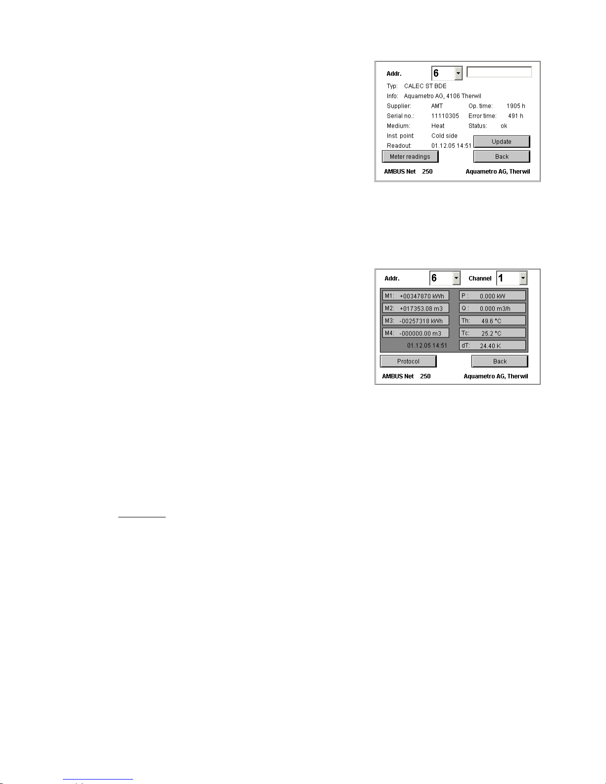
4.3 Reading the meter
The basic features for reading the meter are described in Section
3.3 Meter list, commissioning the M-Bus and automatic meter
search.
• Selecting the meter:
The meter is selected with a drop-down list, which lists all meters by their address.
• Meter data:
Values such as: Type, Info, Supplier, Serial No, Medium,
Installation point, Operating time, Error time and Status are
values that AMBUS
®
Net reads directly from the meter using
the M-Bus.
• Updating:
The date of the last readout is indicated by "Readout".
Press update to read the most current value.
• Designation:
A 10-character designation can also be assigned to each meter.
This designation is stored in the serial flash card.
The button Meter readings calls up the list of readings and instan-
taneous values which are sorted according to address and channel.
• The pages are sorted according to the meter address (0...250)
• 3 channels per address are possible (units and tariff as per M-
Bus)
• A maximum of 4 meter readings and 5 instantaneous values
are possible per address and channel. Sorting the values is according to the sequence in the M-Bus protocol.
See Section 3.3 for storing a meter protocol in the memory card or downloading a meter protocol via remote
control / Ethernet. For typical data, see section 7 Appendix.
4.4 The usage units
It is often useful to group readings from various meters. Creating usage units simplifies future invoicing when
invoicing refer to groups of meters
AMBUS® Net is able to group together any meter readings of similar or different meters. Such groups are
called usage units. Any meter reading assigned to a usage unit can be allocated a text for designation purposes.
22
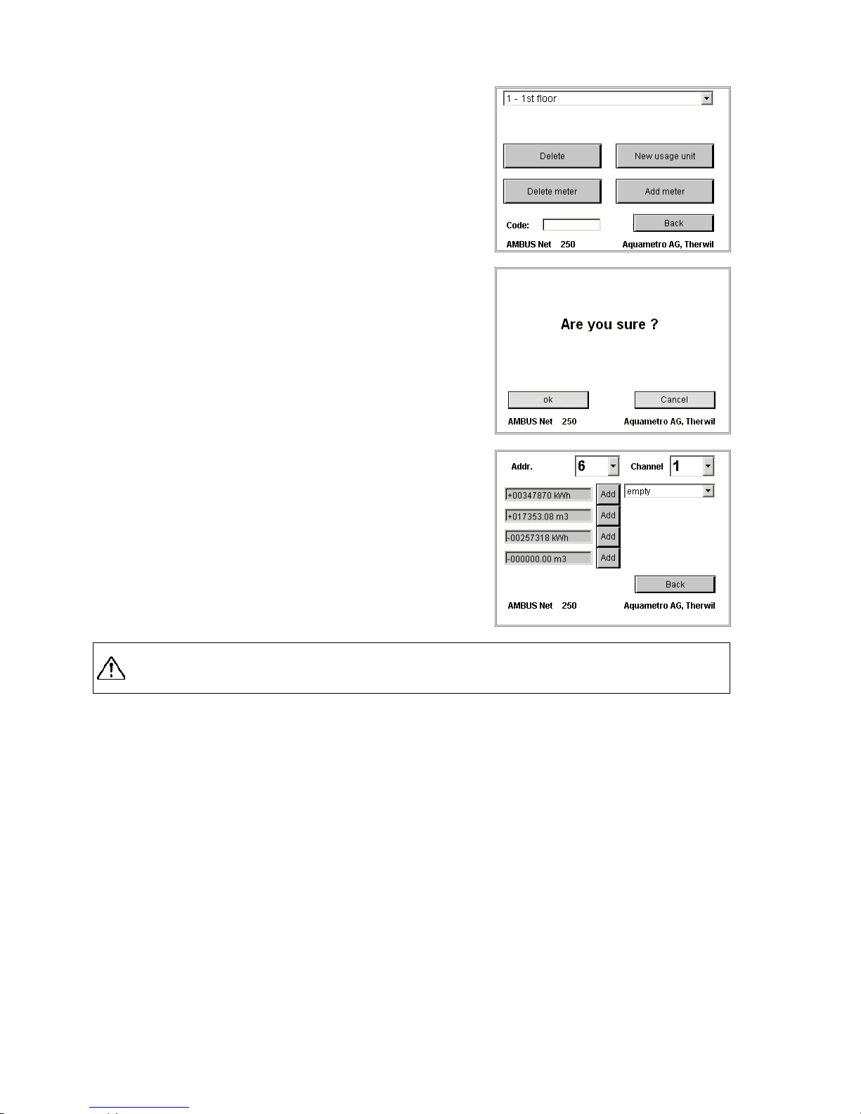
Select from the main menu to create a usage unit:
Modify usage unit
• With the button "New usage unit", the designation of a new
Usage Unit (UU) can be entered via the keypad which is then
displayed.
To the left, near the designation is the internal number of the
UU. This is important for protocols.
• The number of usage units available can be selected in the
scroll-down list.
Modify usage unit / Delete (security prompt)
• Usage units that are incorrectly entered or no longer required
can be deleted using the button "Delete". Since this process
cannot be reversed, the prompt requires confirmation
(ok / Cancel).
Modify usage unit / Add meter
• The button "Add meter" enables any meter readings be as-
signed to the selected usage units.
• Find the address of the particular meter to select (0…250). All
meter readings known to AMBUS
®
Net are available over the
additional channel selection (3 channels per address).
• A common media designation (heating, heat, hot water, cold
water, gas, electricity …) can be added to each meter reading
to be assigned using the drop-down list.
• Press "Add" to assign a meter reading: AMBUS® Net confirms:
“Meter ‚n’ added where n stands for meter reading 1...4.
The number of usage units and the number of assigned meters are limited.
Note: Number of UU times number of meters must be < 250.

23
Modify usage unit / Delete meter
Meter readings that are incorrectly entered or no longer required
can be removed from the usage unit.
• The button "Delete meter" calls up the delete menu:
• Select the meter reading to be deleted,
• And confirm with “Delete".
Access code for usage unit
• A separate 8 numerical character access code can be as-
signed at system level to each usage unit. Users with no system access have separate access to the usage unit by entering
the usage unit code.
• A user has access to several usage units by entering the same
code a number of times (authorization groups).
If a user is in the system having entered the usage unit code,
then only those usage units with the same code are visible.
Direct access to the meters or to the system settings is not
possible.
• Users with the usage unit code cannot alter the code.
All data concerning usage units are stored on the serial flash card.
Select from the main menu to read out a usage unit:
Read out usage unit
• The number of usage units available can be selected in the
scroll down list.
• Each line displays the medium, the meter reading, address and
serial number of the meter.
• Updating:
Updating the data is indicated by: "Readout:". Press "update" to
read the most current values.
o In addition, with the "Data logger" option it is possible to store a
protocol on the CF card or store it directly on the PC remotely.
Typical data are given in Section 7 Appendix.
4.5 Monitoring the m e t e rs: the analysis usage unit
It may be seen that, in the scroll-down list of usage units, there is one with the name "Analysis." One (optional) logger function is able to analyse one particular usage unit: The meters of the analysis usage unit are
protocolled in a fixed time raster for 15 minutes (see also section 1.1):
• The number of meters for which the analysis usage unit can be used is a maximum of 5.
• The analysis usage unit itself cannot be deleted.

24
4.6 Data logger (optional)
The optional data logger records event- or time-controlled data and stores these in the plug-in data memory (CF card).The time interval can be set to between 1 minute and
12 months. If the AMBUS® Net is not equipped with the logger function option, then the update rate is fixed at once per day. The reading is carried out shortly before 24.00.
The logger function (optional)
The keys on either side are used to determine:
1. Which data are to be recorded.
2. In which time interval the data are to be read and recorded.
3. the sequence of data by meters or usage units
4. Whether the data are partitioned according to size or time.
The following table describes the functions of the keys and the names of the logger
data:
Settings of the Logger format
Usage units protocol
Plant protocol
Settings of the
Logger function
Description
Max. size of data
(size-controlled)
Data per month/ data
per day (time-
controlled)
Max. size of data
(size-controlled)
Data per month/data
per day
(time-controlled)
Billing date 1,
Billing date protocols, readout is made at 23:30 on the given day
MEMN_nnn.CSV
MNyymmdd.CSV
MEMA_nnn*.CSV
MAyymmdd.CSV
Interval
Logger data, data recording within the preset time interval
LOGN_nnn.CSV
LNyymmdd.CSV
LOGA_nnn.CSV
Layymmdd.CSV
Fault
Error protocols. The following status messages from a meter are regarded
as faults: No answer, Error, Alarm
ERR_nnn.CSV
Eryymmdd.CSV
ERR_nnn.CSV
Eryymmdd.CSV
Analysis
Analysis data: 5 selected meters can be read in parallel to the logger
function in 15 minute intervals for a defined time period (see sect. 0
Monitoring the meters: the analysis usage unit.)
AN_nnn.CSV
ANyymmdd.CSV
AN_nnn.CSV
ANyymmdd.CSV
Logger format
Usage unit protocol
Meters are arranged according to usage units, meters not assigned to usage units are not shown.
Plant protocol
All meters are listed according to their address.
Max. fle size
Exceeding the file size causes the creation of a new data file (size-controlled)
Files per month
A new data file is created at the beginning of each month (time-controlled). For logger intervals typically between 1 hour and n days
Files per day
A new data file is created at the beginning of each day (time-controlled). For logger intervals typically between 1 minute and n hours
* ’nnn’ between 000 and 999 „…A…“ Plant protocol, i.e. meters are displayed according to their address
** ’yymmtt’ year, month, day, e.g. 061231 „…N…“ Usage units protocol, I.e. meters are di splayed according to the structured usage units
25
Setting the logger time interval
The logger time interval can be entered in the entry field on centre screen to the right. This value determines
the time intervals in which the meters are to be read. It can be set to the following ranges:
Minutes Hours Days Months
1 … 59 1 … 23 1 … 28 1 … 12
Important: Reading out an M-Bus plant can take from several seconds to over 1 hour depending
on the number of meters, the baud rate and the amount of data to be transmitted. The following
conditions must therefore be met:
Readout interval > M-Bus readout time
In cases of overflow the data can no longer be stored and the status message: Logger interval
too short! will appear in the default window
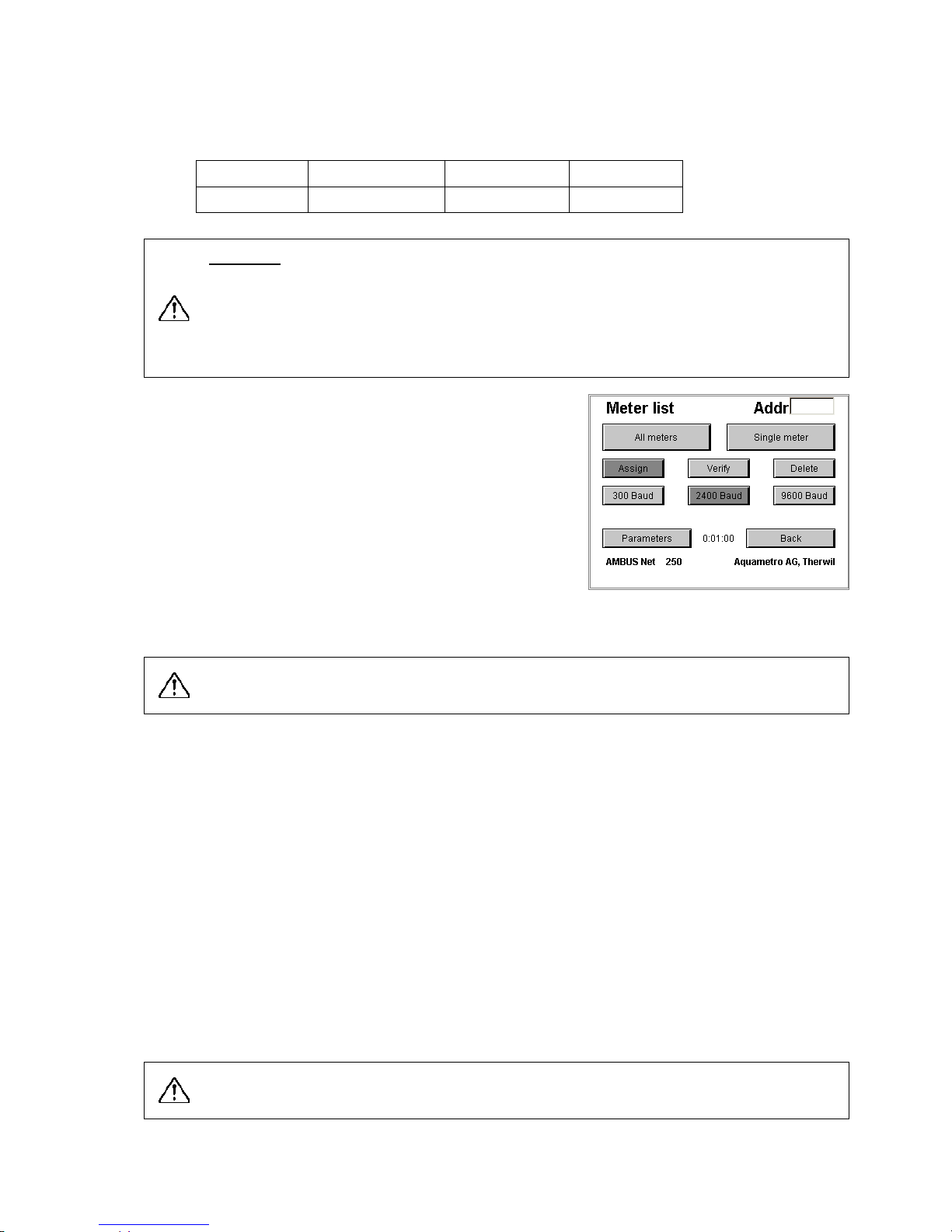
Measuring the M-Bus readout time
The time required for all M-Bus devices to be read out can be
measured as follows:
1. Select Meter list in the field
2. Press the Control button
3. Press the All meters button
AMBUS® Net now reads all meters and shows the time in the de-
fault window at the bottom of the field.:
Contents and format of the logger data are found in section 7 Appendix.
Note: Time-controlled data sizes are generally more advantageous because:
1. the time periods can be more easily limited,
2. an overflow of the memory board is automatically prevented (see below).
Logger: memory size, overflow
The size of the memory board limits the amount of data that can be stored.
Time-controlled logger data are a self-checking function and prevent the system creating an overflow since
the oldest data are automatically deleted.
Size-controlled logger data must be be prevented by the user by one of the following procedures otherwise
the data can no longer be stored in the memory:
• Select the size of the logger data so that:
the size of the memory board > 1000 x size of the data created periodi cally + other data
If the file index 999 is reached, the system then resets the index to 000 so that the oldest data are overwritten
• If this is not possible, the data must first be transferred to another data carrier and the data in the board
deleted.
Note the stipulation above in order to prevent an overflow of the memory board!
(Typical memory requirement in the logger file: 150 – 200 Bytes per meter and reading).

26
Checking the logger interval
To check the logger interval, first read all meters and proceed as
follows:
1 Activate the button "Check" in the field "Meter list"
2 Activate the button "All meters"
3 Wait until the reading time is shown in the field in the centre at
the bottom (example "0:00:25“)
4 Set the logger interval time to at least this time in the field
"Logger function"
Protocol files
The button "Data" shows a directory of all files stored on the
memory card.
If no memory card is available then the following error message is shown:
„Insert memory card please!“
4.7 Meter list, manual meter r eadings
Manual meter readings
Section 3.3 Meter list, commissioning the M-Bus and automatic
meter search described, how meters, e.g. are automatically looked
for and entered via:
Assign – 2400 Baud – all meters.
This search procedure checks the address range in the selected
baudrate from 1 to 250 and enters the addresses in the instru
ments
found.
Meters can also be entered manually, by which the appropriate address is entered in field: Adr.
and the search procedure is started with: Baud – assign – single meter
AMBUS® Net displays, e.g.: "0 meters detected" or "Meter detected"
Meters with an address from 0 to 250 can be entered manually.

27
Removing meters
To delete the entire list, select:
• Delete – all meters
If individual meters are to be removed, select:
• Delete – single meter (having first entered the address to be deleted in field "Adr")
• AMBUS
®
Net displays, e.g.: "all meters deleted or Meter deleted"
1.1.1.1 Checking meters
All meters entered, along with their baud rates, can be checked. Select:
• Verify – all meters
If individual meters are to be checked, select:
• Verify – single meter (having first entered the address to be checked in field "Adr")
This command enables all meters or individual meters to be read and thus checked.
• AMBUS
®
Net display, e.g. "All meters available" or for example "1 Meter not available!"
The time required to read the meters is shown in the display field in the centre at the bottom.
Modify meter list / Meter parameters
When recording, the AMBUS® Net tries to identify every meter
found and to set down the appropriate parameters of the meter
driver. These parameters are and stored in the serial flash card
structured by meters.
If the parameters found for a particular meter are to be checked or
changed, then select: Modify meter list / Meter parameters by
entering the address of the meter in the field: Adr.
The features of the meter are indicated by displaying the appropriate flags in a darker grey tone. By pressing the button, a feature
can be changed, if the meters allow to do so.
1.1.1.2 Baud rate
The 3 buttons at the bottom show the baud rate for which the meter was entered. If the meter can use another baud rates, this can be modified at this point.
1.1.1.3 Aquametro meters
The 3 buttons "AMTRON N“, “CALEC MB“, “Lock alarm“ activate special functions in these Aquametro me-
ters, e.g. reading the text field. The button Lock alarm suppresses an error message which the meters send
if the Lock level is not correctly set (to protect calibration parameters).
These flags are to be changed only by specialists with appropriate training or contact Aquametro
Customer Service for further information.
1.1.1.4 App-Reset (Application Reset)
When this button is activated, AMBUS® Net carries out an "Application reset" before a readout in the M-Bus
command procedure. This command initializes the meter protocol according to the M-Bus standard.
1.1.1.5 Snd_NKE (Send NKE)
When this button is activated, AMBUS® Net carries out a "Snd_NKE" command after every reading. This
command resets the address selection of the meter.
Not all meters respond correctly to the commands: "Application Reset" or "Snd_NKE'
". Check for
correct reading of the meters after a switchover!
1.1.1.6 Auto-Req
Certain meters inform the master with the command REQ_UD2 that more information is available than can
be called up by further read commands. When this button is activated, AMBUS
®
Net responds to this com-
mand by reading out all existing protocols.
28
This option can cause the readout to be considerably delayed. Select the "Auto-
Req" option only if
other important data are to be read!
1.1.1.7 Data in Mem(ory)
Parameters for meters which store the actual meter reading in memory 1 (e.g. EAM current meter).
1.1.1.8 Std-Sel (Standard Selection)
Activates the option Any VIF (alternative method for App Reset).
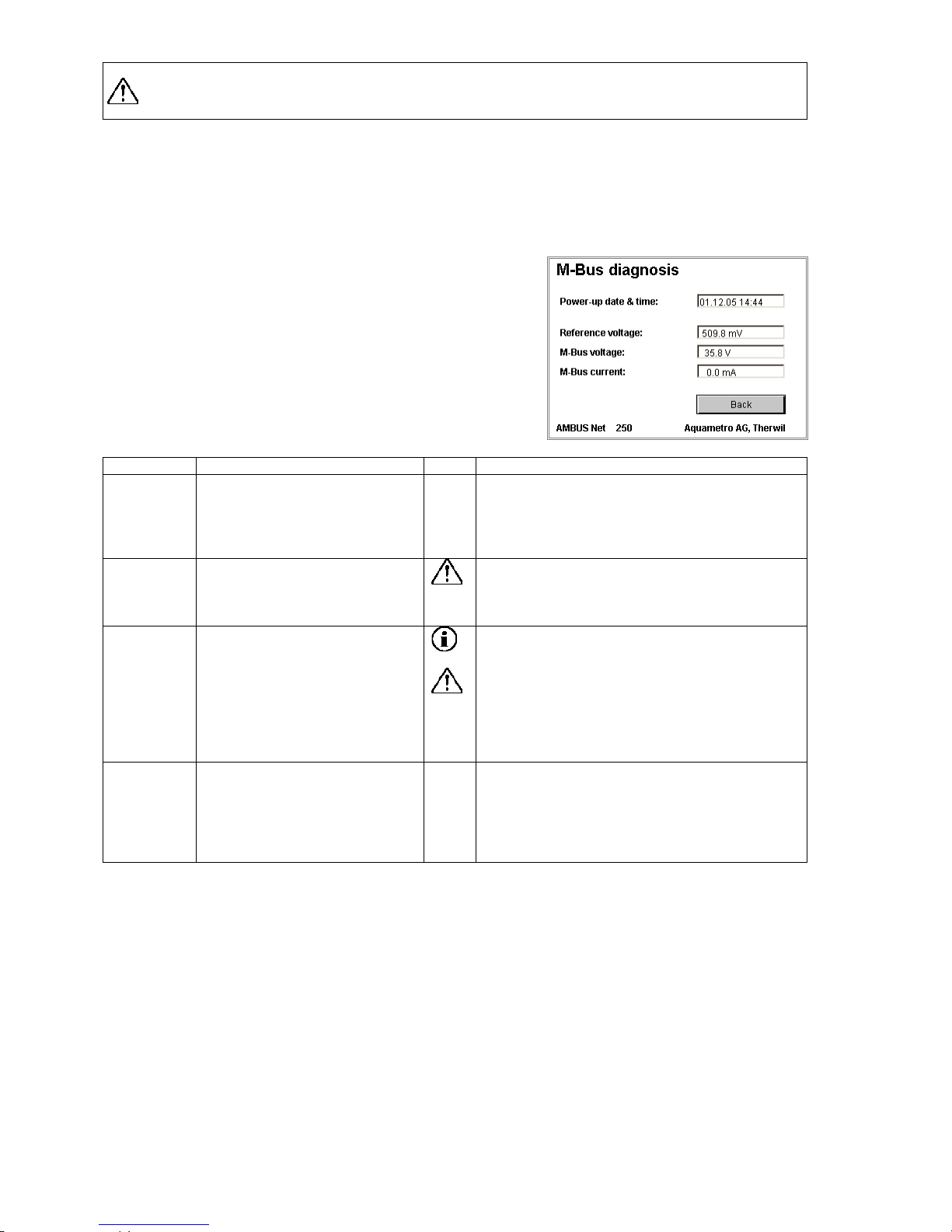
System / M-Bus diagnosis
The menu "M-Bus diagnosis" can be called up via the system me
nu
in order to show electric information about the M-Bus plant.
AMBUS® Net measures the system current, the M-Bus terminal
voltage and an internal reference voltage and then displays them.
Value
Description
Remark
Power-up
date
The date field shows when the
AMBUS® Net was last booted
up. Interruptions in voltage are
of fundamental importance when
monitoring plants.
Reference
voltage
Information on the reference
voltage is for function monitoring
of AMBUS
®
ZS modules. The
voltage is about 500mV.
Please contact Aquametro Customer Service is
the voltage varies by more than 30%!
M-Bus
voltage
The M-Bus voltage is the termi-
nal voltage of the M-Bus network
(terminals 26 / 27). The voltage
is just below 36V.
The voltage can vary slightly during communica-
tion.
• If the value is 24 V when measured over
several seconds, then there is an "Autobreak" error.
• If the value is near 0, then there is a short
circuit in the system.
Please contact Aquametro Customer Service!
M-Bus
current
The current of the M-Bus plant.
The value is proportional to the
number of M-Bus units connected. The theoretical value is
about 1.5mA per unit (1 M-Bus
load).

29
1.1.1.9
5 Remote operation and system integration
5.1 SOAP: Creating a client with .Net
SOAP is an XML-based interface that enables direct data connections to be created between clients over the
Internet, e.g. management software and servers (AMBUS
®
Net).
AMBUS
®
Net makes available data from meters and the usage units via a SOAP interface.
These instructions describe how to create a SOAP client for an AMBUS
®
Net plant.
The document does not claim to be an introduction into SOAP or .Net.
The code extracts are written in the programming language C#.
General description of the Web service
The Web service of AMBUS® Net provides two functions:
getMeter(PrimAddr As unsignedByte) As Meter
PrimAddr
The primary address of the meter
Returned value
The returned data are features of the meter with the primary address "Pri-
mAddr"
getUsageUnit(index As int) As UsageUnit
index
The index number of the usage unit
Returned value
The returned data are the features of the usage unit with the index number "in-
dex"
Features of a meter
If a meter is loaded with the function "getMeter(…)", then it is possible to use it like a local instance. A meter
has various features and is structured as follows:
Public class Meter
{
public byte primAddr;
public string deviceName;
public string desc;
public string type;
public string info;
public string supplier;
public string serial;
public string medium;
public string instPoint;
public string readout;
public string status;
public Display opTime;
public Display errorTime;
public Channel[] channel;
public Meter()
{
channel = new Channel[3];
// …
}
}
public class Channel
{
public Display P;
public Display Q;
public Display Th;
public Display Tc;
public Display dT;
public Display[] M;
public Channel()
{
M = new Display[4];
// …
}
}
public class Display
{
public string value;
public string unit;
public Display() { }
}

30
Features of a usage unit
If a usage unit is loaded with the function "getUsageUnit(…)", then it is possible to use it like a local instance.
A usage unit has various features and is structured as follows:
public class UsageUnit
{
public int index;
public string name;
public string readout;
public string deviceName;
public int size;
public Entry[] entries;
public UsageUnit() { }
}
public class Entry
{
public byte primAddr;
public byte channelNr;
public byte meterNr;
public string medium;
public Entry() { }
}
Linking the Web service to a network
The three steps below following describe how the Web service of AMBUS® Net is linked to a C# project.
1. The first step involves creating a new C#
Windows Application project in MS Visual
Studio .Net.
2. The next step involves creating a Web
Reference in the file AmbusNet.wsdl.
This file is in AMBUS® Net and describes
the Web service.
The following address is to be entered-
as a URL:
http://xxx.xxx.xxx.xxx/AmbusNet.wsdl.
where „xxx.xxx.xxx.xxx“ is the IP
address of the AMBUS
®
Net device. In
this example AMBUS
®
Net has the IP
address: “172.16.1.211“.
The name of the reference can be
freely selected but is still used in the
code.

31
3. The final step is to link the SOAP service to the code. In the example given, the Web reference is called
“NetService“. If another name is selected then this name must be used in the code. Note that a timeout of
approx. 100 ms should be set between two SOAP prompts. This pause guarantees that AMBUS
®
Net is
again ready for the next prompt and that no error occurs. However, if there is an error, then it might take
some minutes until the SOAP service is working correctly again in the AMBUS
®
Net device. The example
below shows how the Web service is linked up:
namespace AmbusNetClient
{
public class AmbusNet : System.Windows.Forms.Form
{
public AmbusNet()
{
InitializeComponent();
}
[STAThread]
static void Main()
{
Application.Run(new AmbusNet());
}
//...
// Function get single meter (m).
public void GetMeter(byte PrimAddress)
{
AmbusNetClient.NetService.Service1 ambus = new
AmbusNetClient.NetService.Service1();
ambus.Proxy = new System.Net.WebProxy(); // empty Proxy
ambus.Url = "http://172.16.1.211/";
AmbusNetClient.NetService.Meter m;
try
{
m = ambus.getMeter(PrimAddress); // remote call
if (m != null){
String deviceName = m.deviceName;
//...
}
}
catch (System.Exception ex)
{
// Error when loading the meter
}
}
// Function get one usuage unit (u).
public void GetUsageUnit (int UnitNr)
{
AmbusNetClient.NetService.Service1 ambus = new
AmbusNetClient.NetService.Service1();
ambus.Proxy = new System.Net.WebProxy(); // empty Proxy
ambus.Url = "http://172.16.1.211/";
AmbusNetClient.NetService.UsageUnit u;
try
{
u = ambus.getUsageUnit(UnitNr); // remote call
if (u != null){
String unitName = u.name;
//...
}
}
catch (System.Exception ex)
{
// Error when loading the usage unit
}
}
}
}

32
5.2 Download prot oc ol
Section 3.4 Network (Windows) explained
how all protocol files that AMBUS
®
Net stored
on the CF card
*)
can be saved to the PC
using a network.
By entering the address:
http://192.168.1.10/CF_Device/
**)
you get the file directory of the protocol files
from AMBUS
®
Net From which you can select.
*)
With data logger option only’
**)
Address when delivered
Click the individual file to:
• either open it
• or save it to a disk
The files can also be opened directly from the
application by entering the complete path with
the URL.
The figure to the right also shows an example
from the Office application: "Excel"
Open File / File name (example):
http://192.168.1.10/CF_Device/LOGA_003.CSV

33
6 Troubleshooting
Symptom
Cause
Remedy
Power symbol does not light
• No power supply
Check power supply including power isolating
terminal acc. to installation instructions
• Short-circuit in the
M-Bus
Check the M-Bus (4-wire) acc. to installation in-
structions AMBUS® Net.
Power symbol lights up but the
display cannot be operated or else
remains dark
• Display not connected
Display should be connected with three cables to
the electronics. Check the cables.
• Serial flash incorrectly
mounted or is defective
Check the seating and position of the serial flash
in its holder.
Power symbol flashes
• Error in M-Bus power
supply
The AMBUS® Net has identified an error in at
least one meter (sect.
4.2). Check the affected
meters (sect. 4.3
) and remove the error at the
meter itself.
No further operation after entering
the access code
• Incorrect access code
Enter the code acc. to sect. 3.2.
• Instruments incorrectly
operated
The code must be entered in the entry field and
confirmed on the access side with OK.
Status message “Initialization of
modem has failed !”
• Incorrect setting
• Modem not plugged in
correctly
• Modem faulty
Verify modem settings and restart device!
Verify telephone connection
Verify modem connection or exchange modem.
Status message "Please insert
memory card”
• Memory card not
plugged in (correctly)
Plug in memory card.
Status message “Logger interval
too short! “
• Logger interval shorter
than time required for
readout
Determine readout time (see section 1.1) and set
logger interval at a higher value.
Status message “No answer”
•
At least 1 meter does
not respond
Verify meter: power supply, M-Bus-connection,
temperature-sensor-connection…
Status message “Error”
• At least 1 meter detected an error
Verify meter: Meter display, temperature-sensorconnection.
Status message “Alarm”
• At least 1 meter detected an alarm
Verify meter: Meter display, temperature-sensorconnection.
Status message “Serial-Flash
not....“”
• Serial flash new or faulty
Verify position of serial flash in holder. Restart
device.
Status message “unlocked”
• AMBUS
®
IS was not
electronically locked
This is no error. The locking is optional.
Menu read meter cannot be se-
lected. The message "No meter
recorded" is displayed
• AMBUS® Net has not
identified meters
Proceed acc. to sect. 3.3.
• Serial flash new or defective
Check the seating and position of the serial flash
in its holder.
AMBUS® Net does not find any
meters
• No or incorrectly con-
nected meters
Check the M-Bus (4-wire) acc. to installation in-
structions AMBUS® Net.
• Incorrect baud rate selected
Check the selected baud rate when entering the
meter acc. to sect. 3.3.
AMBUS® Net does not find all
meters
• Addresses entered twice
Check the M-Bus network with a suitable M-Bus
tool for bus numbers entered twice.
• Poor M-Bus network
Check the M-Bus (4-wire) acc. to installation in-
structions AMBUS® Net.
• Meter with incorrect
baud rate
Check the baud rate of the meter or select a lower
baud rate, if possible.
AMBUS® Net does not find meters
with the address 0
• Address 0 is not auto-
matically supported.
Proceed acc. to sect. 4.7 Meter list, manual me-
ter readings Enter the meter manually or change
the address of the meter.
Menu logger function cannot be
selected.
• Data logger option missing
Logger functions are an option (sect. 2.8); please
contact Aquametro Customer Service.
Status message indicates:
“Serial Flash not....“
• Serial flash new or defective
Check the seating and position of the serial flash
in its holder and restart the instrument.
CF card remains empty
• Data logger option missing
Logger functions are an option (sect. 2.8); please
contact Aquametro Customer Service.
• Card wrongly formatted
Reformat the card acc. to sect. 3.6.
• Incorrect parameters
Check the card acc. to sect: 3.6
• CF card defective
Use a new CF card
Status message "unlocked"
• AMBUS®IS not locked No error: AMBUS® IS was not locked when using
the parameter setting software at start-up.

34
Modem does not function
• Modem incorrectly installed
Check the installation of the modem.
• Incorrect jumper position
on pc board
Check the rider position acc. to sect. 3.5
• RJ-45 cable incorrect
Check the cable and the power outlet.
Analog modem does not function
• MSN No. was erroneously entered
Do not enter a MSN No. with analog modem!
ISDN modem does not function
• MSN No. incorrect
Check the MSN No. acc. to sect. 3.5 .
GSM modem does not function
• Poor reception
Change the position of the adhesive antenna.
• Incorrect SIM card
Check Natel subscription acc. to sect. 3.5.
• PIN not deactivated
Deactivate PIN with Natel.
Ethernet connection does not func-
tion
• Incorrect cable
There are1:1 and crossed cable available!
• IP address / Subnet
mask is wrongly or else
not initialized
Check the network settings or ask your network
supervisor. See sect.: 3.4
Table 6: Troubleshooting

35
7 Appendix
Meter protocol
Meter protocol
Date of protocol:
30.09.2004 08:46
Installation:
Aquametro AG, 4106 Therwil
Type:
CALEC ST
Manufacturer:
AMT Designation:
Staircase 1
Comment:
Aquametro AG, 4106 Therwil
Primary address:
2
Nbr operating hours:
3942
h
Secondary address:
4313074
Nbr hours on alarm:
1 h Medium:
Heat
Status:
ok Installation side flow meter:
cold Side
Channel 1
Read out:
30.09.2004 08:42
Meter 1:
854033
kWh
Meter 2:
15288.9
m3
Meter 3:
Meter 4:
Power:
0
kW
Flow:
0
m3/h
Temperature hot side:
129.8
°C
Temperature cold side:
76.8
°C
Temperature difference:
52.99
K Channel 2
Read out:
30.09.2004 08:42
Meter 1:
0
HCA
Meter 2:
Meter 3:
Meter 4:
Power:
Flow:
Temperature hot side:
Temperature cold side:
Temperature difference:
Channel 3
Read out:
30.09.2004 08:42
Meter 1:
0
HCA
Meter 2:
Meter 3:
Meter 4:
Power:
Flow:
Temperature hot side:
Temperature cold side:
Temperature difference:
made out with AMBUS Net, Aquametro AG, Therwil
Table 7: Example of meter protocol

36
Usage unit protocol
Usage unit protocol
Date of protocol:
30.09.2004 08:58
Installation:
Aquametro AG, 4106 Therwil
Usage unit:
Primary address:
Serial Nr:
Designation:
Meter:
Channel
Medium:
Comment:
Status:
Read out:
Meter reading:
Power:
Appt 1st floor
2
4313074
Distributor 1
1 1 Heating
H-106
ok
30.09.2004 08:48
854033
kWh 0 kW
Appt 1st floor
7
22222222
Distributor 2
2 1 Hot water
W-170
ok
30.09.2004 08:48
1.014
m3 0 kW
Appt 1st floor
7
22222222
Distributor 2
4 1 Cold water
W-170
ok
30.09.2004 08:48
-4.432
m3 0 kW
Made out with AMBUS Net, Aquametro AG, Therwil
Flow: Temp. hot side:
Temp. cold side:
Temp. difference:
Nbr operating hours:
Nbr hours on alarm:
Type:
Manufacturer:
0
m3/h
129.8
°C
76.8
°C
52.99 K 3942 h 1 h CALEC ST
AMT 0 m3/h
30.9
°C
3.7
°C
27.23 K 5532 h 81 h CALEC ST BDE
AMT 0 m3/h
30.9
°C
3.7
°C
27.23 K 5532 h 81 h CALEC ST BDE
AMT
Table 8: Example of Usage unit protocol

37
Installation protocol
Installation protocol
Date protocol:
30.09.2004 08:48
Installation:
Aquametro AG, 4106 Therwil
Prim. address:
Serial Nr:
Chan.
Designation:
Comment:
Medium:
Status:
Read out:
Meter reading 1:
Meter reading 2:
Meter reading 3:
2
4313074
1
Device 1
Second. circuit
Heat
ok
30.09.2004 08:48
854033
kWh
15288.9
m3 2 4313074
2
Device 1
Second. circuit
Heat
ok
30.09.2004 08:48
0
HCA 2 4313074
3
Device 1
Second. circuit
Heat
ok
30.09.2004 08:48
0
HCA 7 22222222
1
Device 2
Main circuit
Heat
ok
30.09.2004 08:48
0.142
kWh
1.014
m3
-13.001
kWh 7 22222222
2
Device 2
Main circuit
Heat
ok
30.09.2004 08:48
0.204
kWh 7 22222222
3
Device 2
Main circuit
Heat
ok
30.09.2004 08:48
54321
HCA
Made out with AMBUS Net, Aquametro AG, Therwil
Meter reading 4:
Power:
Flow:
Temp. hot side:
Temp. cold side:
Temp. difference:
Nbr operating hours:
Nbr hours on alarm
Type:
Manufacturer
0
kW 0 m3/h
129.8
°C
76.8
°C
52.99 K 3942 h 1 h CALEC ST
AMT
3942 h 1 h CALEC ST
AMT
3942 h 1 h CALEC ST
AMT
-4.432
m3 0 kW 0 m3/h
30.9
°C
3.7
°C
27.23 K 5532 h 81 h CALEC ST BDE
AMT
5532 h 81 h CALEC ST BDE
AMT
5532 h 81 h CALEC ST BDE
AMT
Table 9: Example Installation protocol

38

39

Änderungen vorbehalten / Sous réserve de modifications / Modification rights reserved
Copyright © INTEGRA METERING AG, Switzerland
info@integra-metering.com
www.integra-metering.com
Art. Nr. 20275
 Loading...