

Page 1

Mounting and operating instructions
VD 9-925 e 02.2017
AMBUS® Link
The intelligent M-Bus data central for configuration, operation and monitoring of M-Bus
installations as a total system. The integrated web server offers a modern administration
of consumption data.
Table of contents
1 Safety 2
1.1 Intended use 2
1.2 Notes on safety instructions and symbols 2
1.3 Safety instructions and precautionary measures 3
1.4 About the operation manual 3
2 Product description 4
2.1 Areas of application 4
2.2 Device design 4
2.3 Power supply 5
2.4 Interfaces 6
2.5 Memory card 7
3 Scope of delivery and accessories 7
4 Mounting 8
5 Installation 9
5.1 Connection scheme 10
5.2 M-Bus network (field level) 11
6 Commissioning 17
6.1 Switchig on the AMBUS® Link 17
6.2 Operation via AMBUS® Link 18
6.3 Operation via web server 20
6.4 Configuration meter via web server 24
6.5 Creating usage units via web server 29
6.6 Configuring a reporting date reading via web server 32
6.7 Driver configuration via web server 34
6.8 Configuring a logger via web server 37
6.9 Data management via w eb server 45
6.10 System integration via web server 47
7 Maintenance and repair 51
8 Malfunctions and error messages 52
9 Decommissioning, disassembly and disposal 55
9.1 Decommissioning 55
9.2 Disassembly 55
9.3 Disposal 56
10 Technical data 56
10.1 Dimensions 58
11 Appendix 59
11.1 CE declaration of conformity 59
11.2 Export file type csv standard 60
11.3 Export file type csv FULL-DB 65
Page 2

indicates an action or measure which, if performed incorrectly,
CAUTION indicates an action or measure which, if performed incorrectly,
NOTE
COMMENT
1 Safety
1.1 Intended use
The device AMBUS® Link is exclusively intended for the configuration, operation and
monitoring of M-Bus installations as a total system.
Any improper or inappropriate use might result in a state in which the operational safety
of the device cannot be guaranteed anymore. The manufacturer waives any liability for
resulting damages of persons and materials.
1.2 Notes on safety instructions and symbols
The devices have been designed to fulfil modern safety requirements. They have been
tested and delivered in a condition that ensures safe operation. However, improper or
non-intended use of the device may result in it becoming dangerous. Please always pay
attention to the safety instructions in this manual which are accompanied by the following
symbols:
WARNING
WARNING
can potentially cause life-threatening injuries and lead to a high safety risk.
ATTENTION
can cause minor to medium severe injuries.
NOTE indicates a dangerous situation which might lead to material damage,
if not prevented.
COMMENT provides helpful tips and recommendations as well as information for efficient and trouble-free operation.
AMBUS® Link 2
Page 3

in this manual are
This installation instruction is intended for qualified personnel and contains
1.3 Safety instructions and precautionary measures
The manufacturer takes over no responsibility if the following safety instructions and precautionary measures are disregarded:
1. Changes to the device, which are implemented without prior written approval of
the manufacturer, lead to the immediate termination of product liability and warranty.
2. Installation, operation, maintenance, repair and decommissioning of this device
must only be performed by specialists authorised by the manufacturer, operator or
owner of the device. The specialist needs to read and understand the entire installation and operation manual and is obliged to follow these instructions.
3. Control the supply voltage and information given on the type plate, before the device is installed.
4. Check all connections, settings and technical specifications of any available peripheral devices.
5. Open the housing or parts of the housing, which contain electrical or electronic
components, only if the electric energy is turned off.
6. Touch no electronic compo ne nts (ESD sensitivity).
7. Expose the system concerning the mechanical load (pressure, temperature, IP
protection etc.) maximally to the specified classification.
8. For works concerning mechanical components of the system, the pressure in the
pipe system has to be released or the temperature of the medium needs to be
brought to values harmless for humans.
9. No information stated her e or anywhere else releases planners, engineers, fitt er s
and operators from their personal careful and comprehensive evaluation of the respective system configuration in terms of functionality and operational safety.
10. The local working and safety standards and statutes need to be met.
1.4 About the operation manual
The manufacturer reserves the right to change the technical details without prior notice.
The newest information and versions of this operation manual are available at your local
subsidiary or representation as well as on the website.
WARNING
Any liability is waived if the instructions and procedures
not followed!
NOTE
thus no basic working steps. Before putting AMBUS® Link or the system into
operation, the installation and operation manual needs to be read and understood completely.
Keep this manual for later reference!
AMBUS® Link 3
Page 4

2 Product description
We congratulate you for purchasing this high-quality M-Bus data central.
The device AMBUS® Link makes the configuration, operation and monitoring of M-Bus
installations as a total system easier. The integrated web server serves for easy provision
of your consumption data on any terminal devices or subordinate control systems.
2.1 Areas of application
AMBUS® Link is designed for technical building management and also for building services and can be used as follows:
Data concentrator
As central function of your consumption data for analysis and documentation purposes of
all flow and energy meters. For easy administration the integrated web server supports
on all web-enabled terminal devices the user in recording, presentation and provision of
consumption data for utility cost billing or monitoring.
System integration component
With the versatile interfaces AMBUS® Link has to offer you can integrate your consumption data in the simplest way in subordinate building control systems.
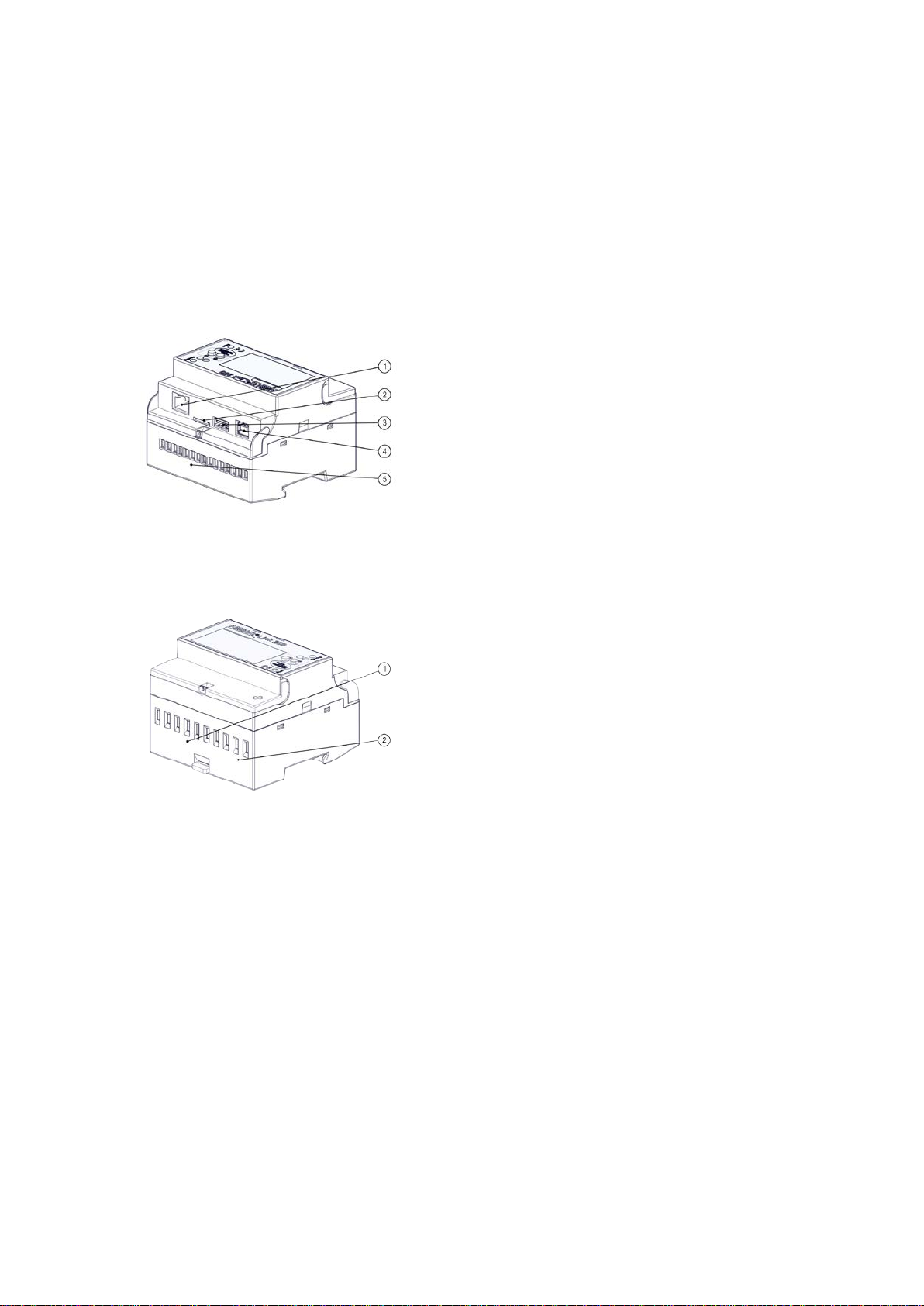
2.2 Device design
AMBUS® Link is intended for control cabinet installation. The device design is defined as
follows:
Optical signals/lights
LED reading and LED scanning
Operating elements
o Enter button
o Function button
AMBUS® Link 4
Page 5

External
Manufacturer recommendations
Switching power supply UNO POWER
Dimensions W x H x D 55×90×84 mm
Protection covers
Mounting rail protection
Mounting rail guide
Status logger, operating status
M-Bus slaves
IP address
Subnet mask
Default gateway
Firmware version
2.3 Power supply
For using the product outside a control cabinet the power supply can be realised as follows.
• Output voltage 24 VDC
• Output power 4.2 A
• Capacity 100 W
AMBUS® Link 5
Page 6
2.4 Interfaces
The data central consists of a TCP/IP interface with integrated data logger and combines
the function of an M-Bus data logger and an M-Bus reading software. Thus the following
software and hardware interfaces are implemented.
2.4.1. Connections
RJ45 LAN connection
Micro SD card slot
USB type A
USB type B
Terminal connection 1-15
Pulse inputs terminals 1-8
Power supply terminals 9-10
AMBUS® Link 6
Page 7

Communication protoc ol s
Micro SD
microSDHC card Transcend Pr emium 400x
1x
AMBUS® Link
1x
microSDHC card
1x
brief instruction
3x
protective covers
2.4.2. Protocols
• Ethernet/LAN/WLAN
• BACnet/IP
• FTP/sFTP
• HTTP
• JSON
• CSV
• POP3
2.5 Memory card
The medium stores all system-specific parameters and contains parts of the operating
system. It is a requirement for op er ati ng the AM BU S® Link.
Options retrofittable via external
router
• LTE
• UMTS/HSPA
• GPRS/EDGE
• Storage capacity 32 GB
• Class 10
• Reading (max.) 60 MB/s
• Writing (max.) 25 MB/s
3 Scope of delivery and accessories
The scope of delivery is described on the delivery note and the content is displayed on
the packaging. Please check all components and delivered parts immediately after receiving the product. Transport damages need to be reported immediately!
AMBUS® Link 7
Page 8

ATTENTION
Control cabinet mounting
AMBUS
ing rail
Control cabinet removal
AMBUS
rail
4 Mounting
Material damage caused by neglected ambient conditions
Danger of malfunction or damag e!
• Assuring accessibility for installation, operation and maintenance
• Protected, dr y surroundings
• Avoid exposure to heat/sun
• Keep a safe distance to sources of electrical nois e
1. Place recesses of the device at the top
edge of the mounting rail
2. Press lightly on the AMBUS®Link
3. AMBUS®Link snaps onto the mounting
rail
®
Link is firmly connected to the mount-
1. Remove the piston
2. Lift AMBUS®Link up from the mounting
rail
®
Link is separated from the mounting
AMBUS® Link 8
Page 9

Life hazard due to electrical shock!
NOTE
5 Installation
Carefully read the following calls for action and warning information to assure a troublefree commissioning.
WARNING
Burns and paralysis resulting in death when touching or grabbing energised system parts.
• Perform installation and maintenance work only when the system is
off power
• W ork on and with voltage shall only be performed by authorised spe-
cialists under consideration of applicable regulations
Apply voltage only to the terminals intended
•
• Safeguarding by external protection elements to assure a safe
switch-off in case of an error
• Install a labelled disconnector (fuse) at an accessible location
• Use a separate fuse circuit for installation
Terminal connections cable cross section
• Terminal connections relay, temperature sensor and M-Bus
• Terminal connections S0 inputs and power supply
o Braid up to 2.5 mm2
o Torque 0.4 Nm
o Braid up to 6 mm2
o Torque 1.3 - 1.6 Nm
AMBUS® Link 9
Page 10

Terminals
Function
Rel 1 NO/Rel 1 C
Relay 1
Normally open
Rel 2 NO/Rel 2 C
Relay 2
Normally open
PT1000 1/PT1000 C
Temperature sensor
PT1000
PT1000 2/PT1000 C
Temperature sensor
PT1000
M-BUS1-/M-BUS1+
M-BUS output 1
Master
M-BUS2-/M-BUS2+
M-BUS output 2
Master
M-BUS3-/M-BUS3+
M-BUS output 3
Master
S0 1A/S0 1B
S0 pulse input 1
Active encoder signal
S0 2A/S0 2B
S0 pulse input 2
Active encoder signal
S0 3A/S0 3B
S0 pulse input 3
Active encoder signal
S0 4A/S0 4B
S0 pulse input 4
Active encoder signal
RJ45
Ethernet port
USB type A
USB interface of type A
WLAN and modems
Level converter and mainte-
5.1 Connection scheme
+24V/GND 24VDC supply voltage
USB type B USB interface of type B
AMBUS® Link 10
nance
Page 11

5.1.1. Power supply:
1. Assure that the power cable
AMBUS
5.1.2. Attach the protective covers
The interfaces are protected
ATTENTION
is voltage-free!
2. The disconnector needs to be switched
off!
3. Flip up the protective cover
4. Loosen the terminal connection
(terminal 9 (+24V DC) /10 (GND))
5. Connect the power supply to
terminal 9 (+24V DC) /10 (GND).
6. Tighten the terminal connection
7. Close the protective cover
®
Link is ready for use
1. Attach included protec t i on cover with
slight pressure
2. Attach included protec t i on cover with
slight pressure
3. Attach included protec t i on cover with
slight pressure
5.2 M-Bus network (field level)
In the following the installation of the M-Bus network with AMBUS® Link is described
Material damage caused by neglected installation conditions
Danger of malfunction or damag e!
• Generously dimension the main cable cross section and possibly
divide it into 3 terminal groups
Apply voltage only to the intended terminals
•
AMBUS® Link 11
Page 12

NOTE
Bus cables between data central and
5.2.1. Connect M-Bus meter
AMBUS
M
5.2.2. Connect the temperature sensor
The temperature sensor is connected
High voltage drops of 5 VAC on the Mterminal node need to be avoided.
• Divide the main strand into several part strands (largest strands)
• Increase cable cross section
• Apply star shape network topology instead of chained network
topology
• Apply no circular network topologies
1. Open the protective cover
2. Loosen the terminal connection
(terminals 10-15)
3. Connect M-Bus participant to terminal
10/11, 12/13 or 14/15
4. Tighten the terminal connection
5. Close the protective cover
®
Link is physically connected with the
-Bus participants
1. Open the protective cover
2. Loosen the terminal connection
(terminals 6-9)
3. Connect the temperature sensor with the
terminal 6/7 or 8/9
4. Tighten the terminal connection
5. Close the protective cover
AMBUS® Link 12
Page 13

COMMENT
5.2.3. Connect alarm relay 1
The relay output is connected
COMMENT
Operating principle alarm relay 1
• Operating principle as normally open
• The following signals appear
o Meter cannot be read out
o Parameter error flag
o M-Bus short circuit
1. Open the protective cover
2. Loosen the terminal connection
(terminals 1/2)
3. Connect the participant to terminal 1/2
4. Tighten the terminal connection
5. Close the protective cover
Operating principle alarm relay 2
• Operating principle as inverted normally open
• The following signals appear
o Meter cannot be read out
o Parameter error flag
o M-Bus short circuit
AMBUS® Link 13
Page 14

5.2.4. Connect alarm relay 2
The relay output is connected
5.2.5. Connect pulse inputs
The pulser is connected
5.2.6. Connect USB type A
The external USB device is
1. Open the protective cover
2. Loosen the terminal connection
(terminals 3/4)
3. Connect the participant to terminal 3/4
4. Tighten the terminal connection
5. Close the protective cover
1. Open the protective cover
2. Loosen the terminal connection
(terminals 1-8)
3. Connect pulser to terminal 1/2,
3/4, 5/6 or 7/8
4. Tighten the terminal connection
5. Close the protective cover
1. Plug the USB type A into the intended
port
connected.
AMBUS® Link 14
Page 15

5.2.7. Connect USB type B
The external USB device is connected.
5.2.8. Connect network cable RJ45
The network cable is connected
1. Plug the USB type B into the intended
port
1. Plug the RJ-45 connector into the intended port
AMBUS® Link 15
Page 16

5.2.9. I nserting a mini SD card
The microSD card is connected.
NOTE
In case of improper handling the microSD card falls into the housig between the
slot and the surface.
• Control the exact positioning of the microSD card before inserting it
Use a slotted screwdriver to insert it.
•
1. Insert the microSD card centred into the
intended port
2. Press the microSD card with slight pressure over the snap-in point
3. The microSD card snaps in the port
AMBUS® Link 16
Page 17

Life hazard due to electrical shock!
Switching AMBUS® Link on
AMBUS
6 Commissioning
AMBUS® Link can be commissioned in two ways, which are described in the following
chapter.
6.1 Switchig on the AMBUS® Link
WARNING
Burns and paralysis resulting in death when touching or grabbing energised system parts.
• Perform installation and maintenance work only when the system is
off power
• W ork on and with voltage shall only be performed by authorised spe-
cialists under consideration of applicable regulations
Apply voltage only to the intended terminals
•
• Protection by external protection elements to assure a safe switch-off
in case of an error
• Install a labelled disconnector (fuse) at an accessible location
Use a separate fuse circuit for installation
1. Start the supply via the disconnector
2. AMBUS® Link starts
3. The reading and scanning LEDs are
"slightly" glowing
4. The display is flashing after 30 sec.
®
Link is ready for use
AMBUS® Link 17
Page 18

COMMENT
COMMENT
6.2.1. Quick commissioning M-Bus network
All meters have been read in
COMMENT
6.2 Operation via AMBUS® Link
The delivery state of the network configuration ex works
• DHCP is activated, IP address is automatically obtained
Functionality of the secondary search
DHCP is deactivated by manual entry of the network parameters
•
Activating DHCP by entering zeros for all network parameters
o
• The search via secondary address is conducted as reverse search
1. Hold the button for more than 5 sec.
2. M-Bus meter search is started via
secondary address
3. The reading and scanning LEDs are glowing "brightly"
4. The operating mode reports SCAN
5. Scanned meters are shown on the
display (slaves)
Finalising the quick configuration of the network parameters
• The set parameters are activated after the configuration has been
finished
• The configur ati on is fi n i shed after de-selecting the last digit
AMBUS® Link 18
Page 19

6.2.2. Quick configuration network parameters
IP address, subnet
are set, the network is configured
6.2.3. Re s tar t AMBUS® Link
AMBUS
preserved
1. Hold the button for more than 2 sec.
first position at IP is selected and
configurable
2. When pressing the button the marked
digit increases by one (0-9)
3. The button confirms the set digit and
jumps to the next
mask and default gateway
1. Hold the button and button
together longer than 5 sec.
2. After releasing the buttons a restart is performed
®
Link restarts and the settings remain
AMBUS® Link 19
Page 20

COMMENT
COMMENT
not connected (connection failed)
COMMENT
COMMENT
6.3 Operation via web server
Operation
• Button for home screen view
• Automatic logout a fter 10 minutes without operation
Role rights
• The rights of each role are fixed and cannot be changed
Administrator «all rights»
•
Standard user «read rights» cannot make changes to the system
•
• In the delivery state a user is predefined
o Admin (administrator role)
Reachability of the web server concerning the firewall
• The communication takes place via TCP, HTTP and websocket
• Port 80 is the communication por t
Explanation of the connection indicator
connected (connection established)
connecting (connection in establishment)
AMBUS® Link 20
Page 21

6.3.1. Language settings
Language is loaded
COMMENT
6.3.2. Create a user profile
The user is created
1. Change language
• German
• English
• French
User administration, password
• Any number of users can be registered in the system
Username minimum length 3 characters
•
Password minimum length 3 characters
•
• Each logged in user can change their personal password
• The standard password for the «admin» user is 123
It is recommended to change the standard password!
1. Enter a username
2. Select role
3. Enter password
4. Enter password again
5. Press
AMBUS® Link 21
Page 22

COMMENT
6.3.3. Change a user profile
The settings are changed
COMMENT
User management as administrator
• A role change for other users is possible
• A password change for other users is possible
1. Select a user
2. Change role
3. Press for role change
4. Enter password
5. Enter password again
6. Press for password change
User management as administrator
• Deleting other users is possible
AMBUS® Link 22
Page 23

6.3.4. Deleting a user profile
The user is deleted
6.3.5. Changing the personal
The
6.3.6. Basic settings
Basic settings are defined and displayed in the
banner
1. Select a user
2. Press
3. Confirm the prompt
password
1. Enter current passwor d
2. Enter new password
3. Enter new password again
4. Press
password is changed
1. Enter name and location
2. Choose time zone
3. Press
AMBUS® Link 23
Page 24

6.3.7. Setting date and time
Date and time
footer
COMMENT
COMMENT
6.4 Configuration meter via web server
1. Set date and time
2. Press
are set and displayed in the
Registration procedure of M-Bus partic ipants
• Network search of connected M-Bus participants
o All meters in the M-Bus network can be registered
• Offline registration of M-Bus participants
o Configuration of the M-Bus network without M-Bus partici-
pants
o Registration of participants after installation in the M-Bus net-
work and first-time network reading
Restrictions of the address range
• When searching with the primary address the range can be freely
selected between 1-250
AMBUS® Link 24
Page 25

6.4.1. Search all meters
The meters in the M
6.4.2. Recording individual meters
The individual meter is saved
6.4.3. Check recorded meters
All meters are available
1. Choose Baud rate
2. Start scan or
-Bus network are registered
1. Choose recording or
2. Set Baud rate
3. Enter the primary and sec on dar y address
of the meter
4. Confirm
1. All registered meters are listed in a table
2. Check status
Found meters - successfully read
Existing meters - M-Bus alarm
Existing meters - Reading error
Missing meters - not yet read out
AMBUS® Link 25
Page 26

COMMENT
6.4.4. Configuring a global reading
All meters are cyclically read out
Definition of the global reading cycle
• The reading cycle is set with «15 min» as a standard
• The reading cycle can be set between 10 sec. - 48h
• The reading cycle is dependent on the entire M-Bus network
cycle
1. Choose reading cycle
2. Press
AMBUS® Link 26
Page 27

COMMENT
COMMENT
NOTE
Bus participants might lead to wrong consumption
M-Bus protocol-specific parameters
• M-Bus protocol-specific values can be overmodulated via
AMBUS® Link
o Meter type
o SND_NKE
o Application reset (including subcodes)
o Designation
o Unit
o Decimal place
o Phase (phase number for electricity meters)
o Tariff (tariff number for meters with several counting modules
for different tariffs)
o Mon. (Month number of a record date meter value)
Single meter configuration for Aquametro and third party meters
• Easy meter configuration for individual meters
• Individual configurations can be saved as templates and applied for
all identical meters
• As a standard for each M-Bus request an SND-NKE and an application reset with subcode «0» are set. The function can be deactivated
by using the checkbox
• Application reset subcodes can be entered into the field
• Meter-specific reading cycles overmodulate global reading cycles
Correct the deci mal pl aces for v alue units
• For decimal places to the left «factor 1000»
• For decimal places to the right «factor 0.001»
Parameter changes for Mdata
• In case of manipulated meters (M-Bus), the meter s need to be new l y
registered (registration)
AMBUS® Link 27
Page 28

6.4.5. Editing meter details
1. State name, location, cost centre and
The individual meter configuration is finished
6.4.6. Deleting a meter
All/individual meters are deleted
or
comment
2. choose meter
type
3. Choose recording or
4. Choose reading cycle
5. Choose Baud rate
6. Tick battery operation
7. Press
8. Confirm the designatio n
9. Mark the designation
10. Choose the unit
11. State phase, divisor, tariff
12. Press
1. Select all or individual meters
2. Press
3. The data is updated
AMBUS® Link 28
Page 29

COMMENT
6.5.1. Defining a usage units
The usage unit is created
6.5 Creating usage units via web server
In the following chapter the creation of user-defined, organisational units (usage units) for
administration of M-Bus participants is described
Administration of usage units
• Formation of organisational units
• User-specific meter gr oup al loc ati o n
1. Press to create a usage unit
1. Enter the name of the usage unit
2. Enter a description
3. Press
AMBUS® Link 29
Page 30

6.5.2. Deleting a usage unit
The usage unit is deleted
6.5.3. Allocating a meter to a usage
The meter
1. Select a usage unit
2. Press
unit
1. Select a usage unit
2. Press
1. Press
2. Select the meter for the usage unit
3. Press
is now allocated to a usage unit
AMBUS® Link 30
Page 31

6.5.4. Deleting a meter from a usage
The meters are now deleted from the
unit
6.5.5. Add a user for a usage unit
The user is now allocated to the usage unit
unit
1. Select a usage unit
2. Press
3. Select the meter of the usage unit
4. Press
usage
1. Select a usage unit
2. Press
3. Press
4. Select the user for the usage unit
5. Press
AMBUS® Link 31
Page 32

6.5.6. Delete a user from a usage
The user is now deleted from the usage unit
COMMENT
6.6.1. Creating a reporting date
The reporting date reading is set for the last day
of the month and the specified reporting date
unit
1. Select a usage unit
2. Press
3. Select the user for the usage unit
4. Press
6.6 Configuring a reporting date reading via web server
Configuration of reporting date reading
• Use numeric input for month, day and hour
o Month (1 -12)
• Report date data available in the export file
o Day (1-31)
o Hour (0 -23)
1. Press
2. Enter month, day and hour
3. Confirm the last day
4. Actively press
AMBUS® Link 32
Page 33

6.6.2. Deleting a reporting date
The reporting date reading is deleted
1. Mark the line
2. Press
AMBUS® Link 33
Page 34

COMMENT
COMMENT
NOTE
Bus participants might lead to wrong consumption
6.7 Driver configuration via web server
Driver configuration for Aquametro and third party meters
• Easy driver configuration for all meters
• M-Bus protocol-specific values can be overmodulated via AMBUS
Link
o Designation
o Unit
o Decimal place
o Phase (phase number for electricity meters)
o Tariff (tariff number for meters with several counting modules
for different tariffs)
• Templates are appl i ed on the bas i s of the following criteria
• Driver templates can be exported and sent to Aquametro
o Mon. (Month number of a record date meter value)
o Manufacturer code
o Version byte
o Number of data records
o Inclusion in third party meter library
o Export file in JSON format
o The exported file is saved in the download folder of the web
browser
®
Correct the decimal places for value units
• For decimal places to the left «factor 1000»
• For decimal places to the right «factor 0.001»
Parameter changes for Mdata
• In case of manipulated meters (M-Bus), the meter s need to be new l y
registered (registration)
AMBUS® Link 34
Page 35

6.7.1. Creating a driver template
The driver template for meters is created
6.7.2. Editing a driver template
1. Select a driver template
Update and save the driver template
1. Select a meter
2. Press
3. Press
2. Press
3. Enter the device designation
4. Choose the device designation from the
value definitions
5. Set the target unit
6. Enter the phase and div is or
(if required)
7. Mon. enter (if required)
8. Enter tariff (if required)
9. Press
AMBUS® Link 35
Page 36

6.7.3. Apply driver template to meter
All meters with the same manufacturer code are
configured
6.7.4. Export driver template
The meter driver template is exported
1. Select a driver template
2. Press
3. Press
according to the driver template
1. Select a driver template
2. Enter a file name
3. Press
4. Execute save file as
AMBUS® Link 36
Page 37

6.7.5. Import driver template
Import driver template
6.7.6. Delete driver template
The reporting date reading is deleted
COMMENT
1. Press
2. Press
3.
4. Press
6.8 Configuring a logger via web server
1. Select a driver template
2. Press
Correctly choose reading times
• Reading times depend on the circumstances and the dimensioning
of the M-Bus network
The reading cycle applies for the entire M-Bus network
•
For 100 or more meters at least 2 min per reading
•
For 250 meters at least 5 min per reading
•
AMBUS® Link 37
Page 38

COMMENT
COMMENT
6.8.2. Set up an NTP time server
The system time is synchronised with the defined server
6.8.1. Network settings
Established connection with AMBUS
Define network parameters via DHCP
• DHCP needs to be activated at the router
• Set that the IP address is automatically allocated from the DHCP
server
1. Enter IP address of the AMBUS® Link
2. Enter subnet mask
3. Enter the gateway of the router
4. Enter the DNS server address 1 and 2 on
demand
5. Activate on demand
6. Press
®
Link
Requirements for correct logging of consumption data
• The system time is correctly set (see basic settings)
• AMBUS® Link is working with UTC time
• The UTC time is calculated with the defined local time and time zone
The system time is defined via an NTP server
•
e.g. metasntp 11.admin.ch
o
AMBUS® Link 38
1. Define the NTP server
2. Press
Page 39

6.8.3. Logging the temperature sen-
The temperature
6.8.4. Logging the S0 inputs
S0 input is logged
COMMENT
sors
1. Mark the line
2. Activate
sensor is logged
1. Mark the line
2. Enter the starting value
3. Activate
Using the level converter
• Using the level converter via USB type B interface
• Setting «Default» complies with 2400 Baud
• When the level converter is activated the status changes
o to web server «Level converter RS232» is on
o to AMBUS® Link «[< - - >]» is on
• The logger function is deactivated in the level converter operation
AMBUS® Link 39
Page 40

6.8.5. Switching on the level con-
The level converter is activated
COMMENT
verter
1. Choose the Baud rate of the meter
2. Activate the level converter
3. Press
Filtering the status messages
• Status details
o 0 - After switching on the device, start process "logger"
o 1 - M-Bus overcurrent
o 2 - Start cloud upload
o 3 - Error cloud upload
o 4 - Cloud upload successfully completed
o 5 - Start FTP/sF TP upl oad
o 6 - Error FTP/sF TP upl oad
o 7 - FTP/sFTP upload successfully completed
o 8 - Meter (serial number), reading failed
o 9 - Email transmission failed
o 10 - Error on a meter
It is recommended to regularly delete the status messages to prevent
•
long updating times.
AMBUS® Link 40
Page 41

6.8.6. Status messages
Status information is displayed
6.8.7. Message type selection
Message type selected
1. Enter status number
2. The data is updated
3. Press for actualisation
1. Select a message
a. Error
b. Warning
c. Info
2. The data is updated
3. Press for actualisation
AMBUS® Link 41
Page 42

6.8.8. Delete status messages
All status messages are deleted
COMMENT
6.8.9. Sending alarms via email
1. Enter email server and port
Alarms have been sent via email
1. Press
Configuration email
• Several email addresses possible by using a semicolon as separator
• Sending of
o M-Bus alarm (warning)
o Reading error (error)
2. Enter name and email address o f the
sender
3. Enter email address of the recipient
4. Select connection type
• TCP
• SSL
• TLS
5. Select login
• Login
• Plain
6. Adjust timeouts
7. Enter username and password
8. Activate/deactivate function
9. Press
AMBUS® Link 42
Page 43

COMMENT
6.8.10. Export logger configuration
Data is exported
6.8.11. Import logger configuration
Logger configuration is imported
NOTE
Configuration logger
• Backup file
o Export file in JSON format
o The exported file is saved in the download folder of the w eb
browser
• Contains complete logger configuration
o Without meter
1. Press for saving the current
logger configuration
2. Data is downloaded
1. Press (format JSON)
2. Select file
3. File is
displayed
Failed firmware updates might lead to a loss of data
• Perform configuration logger «Backup» (6.8.10)
AMBUS® Link 43
4. Press
5. Backup is imported
Page 44

COMMENT
6.8.12. Firmware package update
Updates have been installed
COMMENT
Install firmware updat e s
• Updating individual functional units
o M-Bus logger
o BACnet/IP
o Connect
o Websocket
o Web server
• Package update as for mat «*.ipk»
• Multiple selection for package updates possible
• Fail-safe firmware update with intermediate storage
1. Press
2. Select file
3. Press
4. File is uploaded
5. Data is displayed in table
6. Repeat step 1-4 for ad dit ional fil es
7. Updates are installed
8. Execute firmware package overview
(see 6.8.13)
9. Press
Installed firmware pack ages
• View of all firmware packages with time stamp and status
• Control of successful installations with the time stamp
• The update process might take several minutes
AMBUS® Link 44
Page 45

6.8.13. Firmware package overview
The overview of installed updates is refreshed
6.9.1. Overview of meter statuses
The table with current meter statuses is displayed
COMMENT
1. Press
6.9 Data management via web server
The function "Update" reads the current data of the last reading process from a
database. No M-Bus reading is performed.
1. Select of a meter
AMBUS® Link 45
Page 46

6.9.2. Viewing meter statuses
Data of selected meters are shown
Meter statuses are
Comparison with the previous day, week,
month or year is displayed
6.9.3. Print/save charts
Charts are saved or printed
1. Selecting a meter
2. Press
1. Select for diagram view
2. Choose starting time
displayed from starting time.
1. Select for diagram view
2. Choose starting time
3. Press
4. Select Print or Save
AMBUS® Link 46
Page 47

COMMENT
6.10 System integration via web server
Data export
• Data can be exported manually or via FTP/sFTP
• For a larger time period the process takes several minutes
• Export type CSV
o Option «Standard» see chapter 11.2
o Option «Standard» see chapter 11.3
o Enter separator
• The exported fil es ar e saved in a compressed ZIP archive (DataExport.zip) in the download folder of the web browser.
• FTP files are saved after each reading cycle in the indicated directory (push process)
Integration of a cloud solution
• ISO 500001 certified energy management software solution
• Please contact your Aquametro contact person
Integration via BACnet/IP
• All registered M-Bus meters are also available as BACnet objects
• AMBUS® Link is BBMD-capable
• At maximum 16 BBMD servers can be set up
• The M-Bus can be permanently read out
o Permanent reading: It is not waited for the next reading cycle. As
soon as the reading is finished the next query is started
AMBUS® Link 47
Page 48

6.10.1. Export meter data
Export file is generated and saved in the ZIP
archive
6.10.2. Meter data upload via
1. Define information about FTP/sFTP
Data is pushed to the FTP/sFTP server
COMMENT
1. Select individual meters or all meters
2. Select a time period
3. Choose a medium (optional)
4. Select export type
5. Select options
6. Select a separator
7. Press
FTP upload File path
10-46110815-20161122102732
ID-Secondary address-YearMonthDayHourMinuteSecond
ID : Internal AMBUS Link identification number (configur ati on met er 6.4.5)
FTP /sFTP
server
• Server address
• Port
• Username
• Password
• Path
2. Activate/deactivate upload
AMBUS® Link 48
3. Activate/deactivate
4. Select export type
5. Select a separator
6. Select options
7. Select language
8. Press
9. Press (manual upload)
Page 49

6.10.3. Upload of meter data via cloud
1. Specify information about the cloud
Data is pushed in the cloud
6.10.4. Switch on BACnet/IP
1. Define BACnet settings
BACnet/IP is switched on
server
• Server address
• Port
• ID
2. Activate/deactivate upload
3. Press
4.
5. Press (manual upload)
6.
• D-Net number
• Port number
• Device inst ance nu mb er
2. Activate/deactivate
3. Activate/deactivate
4. Activate/deactivate
5. Press
AMBUS® Link 49
Page 50

6.10.5. Define a BACnet BBMD server
BACnet BBMD server has been defined
6.10.6. Delete BACnet BBMD server
BACnet BBMD server is deleted
1. Define BACnet BBMD settings
• IP address
• Subnet mask
• UDP port
2. Press
1. Select server
2. Press
AMBUS® Link 50
Page 51

WARNING
used.
7 Maintenance and repair
The product requires no maintenance. Cleaning shall only be performed with a moistened cloth. No solvents or other aggressive agents shall be applied.
Risk of death by electric shock from live cables and parts.
Risk of electric shock!
1. Perform installation and maintenance work only when the system is off
power.
2. Work on and with voltage shall only be performed by authorised specialists under consideration of applicable regulations.
3. For connections to the power supply only the intended terminals shall be
AMBUS® Link 51
Page 52

Symptom
Reason
Correction
LEDs are not glowing
• No supply available
Check power supply incl.
AMBUS®Link finds no me-
• No or wrongly installed
Check meter installations
• Wrong Baud rate select-
Check the selected Baud
AMBUS®Link finds not all
• Addresses have been
Control M-Bus network with
• Meter with wrong Baud
Control the Baud rate at the
The operating status shows
• No mini SD ca rd in the
• Disconnect AMBUS® Link
8 Malfunctions and error messages
supply isolation termi n al
according to installation
manual
ter
meters
«OFF» during startup and
«MMC Missing» appears
on the display
meters
ed
assigned twice
rate
slot.
rate according to chapter
6.4.1
a suitable M-Bus tool f or bus
numbers, which have been
assigned twice
meter, select a lower Baud
rate at the meter, if possible.
from the power supply
• Enter a microSD card in the
respective slot
Switch AMBUS® Link on
•
AMBUS® Link 52
Page 53

Login
• Wrong username or
• Enter correct username
Create a user profile
• The current password is
• Enter the password correct-
• The minimum length of 3
• Enter a password with at
• The details have not
• Repeat the registration and
password
not corresponding with
the repeated password
characters has not been
complied with
and password
ly again
least 3 characters
AMBUS® Link 53
been filled out completely.
fill out all details
Page 54

Changing the password
• The current password is
• Enter the password correct-
• The minimum length of 3
• Enter a password with at
Search all meters
• Primary address range
• Set the primary address
Define BACnet/IP BBMD server
• A BBMD server with an
• Select new, unique IP
not corresponding with
ly again
the repeatedly entered
password
characters has not been
least 3 characters
complied with
set too small
identical IP address already exists.
range generously
address
AMBUS® Link 54
Page 55

WARNING
used.
Control cabinet removal
9 Decommissioning, disassembly and disposal
Risk of death by electric shock from live cables and parts.
Risk of electric shock!
1. Perform installation and maintenance work only when the system is off
power.
2. Work on and with voltage shall only be performed by authorised specialists under consideration of applicable regulations.
3. For connections to the power supply only the intended terminals shall be
9.1 Decommissioning
1. Disconnect from all sources of energy
2. Remove all cables and
connections from the device
3. Remove the device from the
system
AMBUS® Link is out of service
9.2 Disassembly
1. Remove the piston
2. Lift AMBUS®Link up from the mounting
rail
AMBUS® Link 55
AMBUS®Link is separated from the
mounting rail
Page 56

Basic data
Power supply:
24 VDC
Power consumption
Max. 1A
Temperature range
0 - 55°C
Display
LCD display with background lighting (128x64 dots)
Weight
Approx. 400g
Installation
35mm DIN rail
Housing:
Polycarbonate, recyclable, non-flammable
Evaluation
Web server/diagram
Data export
As JSON or CSV file
Data memory
Micro SD card (needs to have more than 32 GB free
Firmware update
Yes, is possible
Configuration
Local and remote configuration with web browser
Inputs
3x M-Bus
9.3 Disposal
At the end of the life cycle this product must be recycled or disposed according to the
local provisions.
Remove batteries and accumulators and dispose them separately.
The separate collection and recycling of old devices helps to preserve natural resources
and assures that they are disposed in a way that the protection of the environment and
nature is assured.
10 Technical data
space available)
2x temperature PT1000 (-20°C to +100°C)
4x S0
AMBUS® Link 56
Page 57

M-Bus
Baud rates
300, 600, 1200, 2400, 4800, 9600
Compatibility
Heat, water, fas and electricity meter with M-Bus accord-
Level converter
Integrated
M-Bus closed current
Max. 375mA (250 x 1.5mA)
Number of M-Bus slaves
Max. 250 (see order information)
Galvanic separation
Yes
Short-circuit protection
Yes
Overload protection
Yes
BACnet/IP
Specifications
All M-Bus meters registered on AMBUS® Link are auto-
BBMD
Yes
Protocol Implementation Con-
The PICS document can be found on our website at:
Outputs
2 x relay
Interfaces
1x Ethernet 10/100 Base RJ45
1x USB type A
1x USB type B
ing to EN 13 757-2,-3 (former EN1434-3)
Transparently operatable via USB type B
matically translated into BACnet/IP objects.
formance Statement
www.aquametro.com/ambuslink
AMBUS® Link 57
Page 58

Approvals and norms
Safety
CE-declaration
EMC metering
EN 610000-6.2
Interference immunity
EN 61000-6-3
M-Bus norm
EN 13757-2,-3
Energy management
Suitable for ISO 50001
BACnet
Certified
10.1 Dimensions
AMBUS® Link 58
Page 59

11 Appendix
11.1 CE declaration of conformity
AMBUS® Link 59
Page 60

Date/Time(UTC) PrimaryAddress Serial ManufacturerId Version
26.01.2017 16:12 10 4800181 AMT 192
26.01.2017 16:27 10 4800181 AMT 192
26.01.2017 16:43 10
4800181 AMT 192
Medium Energy Energy_Einheit Volume
Volume_Einheit
Heat (outlet) 2709840000 Wh 43240.1 m^3
Heat (outlet) 2709870000 Wh 43240.5 m^3
Heat (outlet) 2709890000 Wh 43240.8 m^3
Units for H. C. A . Units for H. C. A._Einheit
Units for H. C. A . Units for H. C. A._Einheit
Power
0 0 86269.3
0 0 86212.8
0 0
86216.5
Power_Einheit Volume flow Volume flow_Einheit Flow temperature Flow temperature_Einheit
W
1.37621 m^3/h 131.759 Degree C
W 1.37584 m^3/h 131.766 Degree C
W 1.37555 m^3/h 131.759 Degree C
Return temperature Return temperature_Einheit Temperature difference Temperature difference_Einheit Energy (per kelvinliter)
76.9198 Degree C 54.8394 K 1.14265
76.9266 Degree C 54.8395 K 1.14264
76.9061 Degree C 54.8531 K 1.14264
Energy (per kelvinliter)_Einheit Mass (per liter) Mass (per liter)_Einheit On time On time_Einheit
Wh 0.974371 kg 45865 h
Wh 0.974366 kg 45866 h
Wh 0.974362 kg 45866 h
On time / V T =3 (Error) On time / VT=3 (Error)_Einheit Volume (per input pulse ch. 0) Volume (per input pulse ch. 0)_Einheit Units for H. C. A. (per input pulse ch. 0)
0 h 0.00101 m ^3 1
0 h 0.00101 m ^3 1
0 h 0.00101 m ^3 1
Units for H. C. A. (per input pulse ch. 0)_Einhe
Units for H. C. A. (per input pulse ch. 0)
Units for H. C. A. (per input pulse ch. 0)_Einh
Address Address_Einheit
1 10 None
1 10 None
1 10 None
11.2 Export file type csv standard
AMBUS® Link 60
Page 61

Date/time (UTC)
Coordinated world time
PrimaryAddress
Primary address
Serial
Secondary address/serial number
ManufacturedId
Manufacturer identification number according to M-Bus
Version
M-Bus version byte
Medium
Medium
Energy
Energy value
Energy unit
Unit of the energy value
Volume
Volume
Volume unit
Unit of the volume
Fabrication Fabrication_Einheit Timestamp (future value) / Monat 1 Timestamp (future value) / Monat 1_Einheit Timestamp (future value) / Monat 2
4800181 None 2024246144
UTC 2040143744
4800181 None 2024246144
UTC 2040143744
4800181 None 2024246144
UTC 2040143744
Timestamp (future value) / Monat 2_Einheit Customer Customer_Einheit Metrology (firmware) version Metrology (firmware) version_Einheit
UTC 0 None 10500 None
UTC 0
None 10500 None
UTC 0 None 10500 None
Hardware version Hardware version_Einheit
0 None
0 None
0 None
AMBUS® Link 61
Page 62

Units for H.C.A.
Heat Cost Allocator allocation formula
Units for H.C.A. Unit
No unit ("none")
Units for H.C.A.
Heat Cost Allocator allocation formula
Units for H.C.A. Unit
No unit ("none")
Power
Power
Power unit
Unit of the power
Volume flow
Flow value
Volume flow_unit
Unit of the flow
Flow temperature
Flow temperature
Flow temperature_unit
Unit of the flow temperature
Return temperature
Return temperature
Return temperature_unit
Unit of the return temperature
Temperature difference
Temperature difference
Temperature difference_unit
Unit of the temperature difference
Energy (per kelvin litre)
Correction factor
Energy (per kelvin litre)_unit
Unit of the correction factor
Mass (per litre)
Density
AMBUS® Link 62
Page 63

On time
Operating hours
On time_unit
Unit of the operating hours
On time/VT=3 (error)
Error hours
On time/VT=3 (error)_unit
Unit of the error hours
Volume (per input pulse ch. 0)
Pulse value
Volume (per input pulse ch. 0)_unit
Unit of the pulse value
Units for H.C.A. (per input pulse ch. 0)
Pulse value auxiliary meter 1
Units for H.C.A. (per input pulse ch.
No unit ("none")
Units for H.C.A. (per input pulse ch. 0)
Pulse value auxiliary meter 2
Units for H.C.A. (per input pulse ch.
No unit ("none")
Address
Primary address
Address_unit
No unit ("none")
Fabrication
Fabrication number
Fabrication_unit
No unit ("none")
Time stamp (future value)/month 1
Reporting date 1
Time stamp (future value)/month 1_unit
Unit of the reporting date
0)_unit
0)_unit
AMBUS® Link 63
Page 64

Time stamp (future value)/month 2
Reporting date 2
Time stamp (future value)/month 2_unit
Unit of the reporting date
Customer
Customer text field
Customer_unit
Text
Metrology (firmware) ve rsio n
Firmware version
Metrology (firmware) version_unit
No unit ("none")
Hardware version
Hardware version
Hardware version_unit
No unit ("none")
AMBUS® Link 64
Page 65

Device .ID
Internal AMBUS Link i dentification number (configuration meter)
AddressMode
Primary switch - secondary reading
PrimaryAddress
Primary address
ManufacturedId
Manufacturer identification number according to M-Bus
Serial
Secondary address/serial number
Version
M-Bus version byte
Device.Id AddressMode PrimaryAddress ManufacturerId Serial Version Medium Device.Active ReadoutCycle BaudRate
29 0 10 AMT 4800181 192 H eat (outlet) -1 0 2400
29 0 10 AMT 4800181 192 H eat (outlet) -1 0 2400
29 0 10 AMT 4800181 192 H eat (outlet) -1 0 2400
BACNetDevInstNumber
Name Site CostUnit CommentStr LoggerLastReadoutOk LoggerReadoutState LoggerReadoutCycle MediumGroup Battery
4194077 CALEC ST 1485440274 1 0 3 0
4194077 CALEC ST 1485440274 1 0 3 0
4194077 CALEC ST 1485440274 1 0 3 0
Position
DescriptionStr UnitStr ScalePower ScaleMantissa EncodeType ValueType StorageNum Tariff ValueDesc.Active
0 Energy Wh 0 0 0 0 0 0 -1
0 Energy Wh 0 0 0 0 0 0 -1
0 Energy Wh 0 0 0 0 0 0 -1
LoggerLastValue
CfgDescription CfgUnit CfgPhase CfgFactor CfgStorageNum CfgTariff TimeStamp Val1 ValueDesc.Id
2709680000 0 0 0 0 0 0 1485303093 2706390000 3438
2709680000 0 0 0 0 0 0 1485304020 2706420000 3438
2709680000 0 0 0 0 0 0 1485304945 2706440000 3438
11.3 Export file type csv FULL-DB
Explanation CSV export (FullDB)
AMBUS® Link 65
Page 66

Medium
Medium
Device.Active
Defines if a meter is logged during reading and transferred with the report. Value 1: Me-
ReadoutCycle
Meter-specific reading cycle (only configuration, without reading)
Baud rate
Baud rate
BACNetDevInstNumber
BACnet device instance number
Name
Name
Site
Location
CostUnit
Cost centre
CommentStr
Comment
LoggerLastReadoutOk
Last successfuly readout (UNIX time stamp)
LoggerReadoutState
Satus of readout
LoggerReadoutCycle
Individual reading cycle (position in dropdown)
ter is logged and transferred
Value 0: Meter is not transferred
Value -1: not configu r ed
Value 0: not defined
Value 1: OK
Value 2: Error
AMBUS® Link 66
Page 67

MediumGroup
Individual meter type (value from dropdown)
Battery
Battery flag
Position
N/A
DescriptionStr
M-Bus parameter name
UnitStr
M-Bus unit
ScalePower
Scale factor for the integrated reading value
ScaleMantissa
Scale factor (mantissa)
EncodeType
Encoding type of the meter in the M-Bus package (e.g.: INT8, INT32, BCD8 or
ValueType
Value MAXIMUM: Meter value is a maximum value over a timespan.
StorageNum
The storage number of the meter value defined by the meter.
VARIABLEDATA).
Within the logging integer-based meter values are listed as numbers, text-based meter
values as text and binary data as text-based hexadecimal characters.
Value MINIMUM: Meter value is a minimum value over a timespan.
Value ERRORSTATE: Meter value is in error status.
Value INSTANTANEOUS: Meter value is an instantaneous value.
Value 0 defines that the associated meter value for the current time has been recorded.
AMBUS® Link 67
A value unequal 0 defines that a meter value at a specific time (defined by the meter
manufacturer) has been recorded.
Page 68

An associated time stamp is also included in the CSV log (time stamp).
Tariff
Tariff
ValueDesc.Active
N/A
LoggerLastValue
Last value
CfgDescription
Designation (manual fr om template)
CfgUnit
Unit (manual from template)
CfgPhase
Phase (manual from template)
CfgFactor
Factor
CfgStorageNum
Storage number (transmitted by meter)
CfgTariff
Tariff (manual from template)
TimeStamp
Time stamp
Val1
Value
ValueDesc.Id
Value identification number
AMBUS® Link 68
Page 69

info@integra-metering.com
www.integra-metering.com
Änderungen vorbehalten / Sous réserve de modifications / Modification rights reserved
Copyright © INTEGRA METERING AG, Switzerland
 Loading...