

Page 1

LOCOnTROLLER
Model LT 150 A
User Manual
Page 2

Page 3

Table of Contents
1. Introduction 5
What’s in the box? 5
1a. THE LT150A HANDSET 6
2. Handset - Before rst use 7
Inserting the rechargeable batteries into the handset. 7
Charging the handset batteries 7
Charger LED indicator codes: 8
Turning the handset on. 8
Turning the handset o. 8
3. System startup procedure 9
Startup: 9
4. System and Error Messages 10
User Induced E-STOP: 10
5. Control of your locomotive 11
Setting speed: 11
Changing direction: 11
Applying brakes: (With brake controller) 12
Stopping/slow down:(Without brake controller) 12
Locking brakes: (With brake controller) 13
Unlocking brakes: (With brake controller) 13
Checking locomotive battery voltages 13
Turning on the lights 14
Sounding the horn 14
Turning the bell on and o 14
Ditch lights 15
6. Setup Menu 15
Entering the Setup Menu: 15
Changing menu settings. 16
Description of functions: 17
Description of functions(continued): 18
Event System: 19
7. The LT150A (hardware setup) 20
Connections of the LT150A 20
Installing the radio Tranceiver 21
Installing the system connector 22
Installing the Light and Aux Connector 23
Locomotive Brake connector 24
Train brake connector 25
MU connector 26
Brake Controller types 27
Installing the speed sensor 28
9. Wiring Diagram 30
Integral Circuits Critter Control Model LT150A Manual
Document Version 1.0 ©2016 Integral Circuits,
Page 4
4
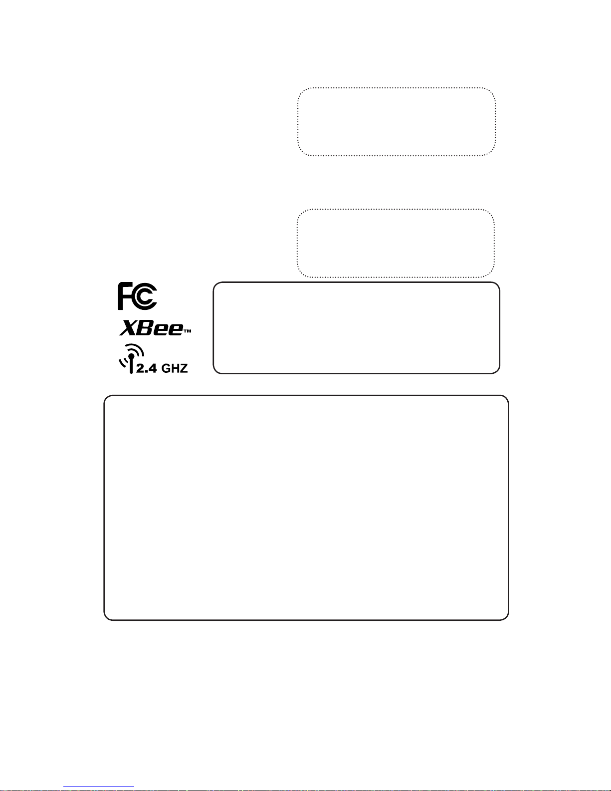
PRELIMINARY
Locomotive MAC Address and S/N
Handset MAC Address and S/N
The LT150A utilizes a matched pair of radios . the following two labels are the addresses and serial numbers of the locomotive unit and handset
If there is no label here , the same label/
information can be also found on the radio
tranceiver and the mounting side of the
Locomotive unit.
If there is no label here, the same information can be found on the back of the
handset.
Contains FCC ID: MCQ-PROS2B
The enclosed device complies with Part 15 of the FCC Rules.
Operation is subject to the following conditions:
(i.) this device may not cause harmful interference and
(ii.) this device must accept any interference received,
including interference that may cause undesired operation.
WARNING
Radio Transmitting Device
This handset contains a low power “spread spectrum”
radio transmitter. While the eective radiation of this
device is less than 200mW and though care has been
taken to design this handset such that the location of
the antenna minimizes human exposure to its 2.4GHz
energy, care should be taken to hold the handset per design to limit futher exposure and to improve operational
performance.
Page 5
5
PRELIMINARY
1. Introduction
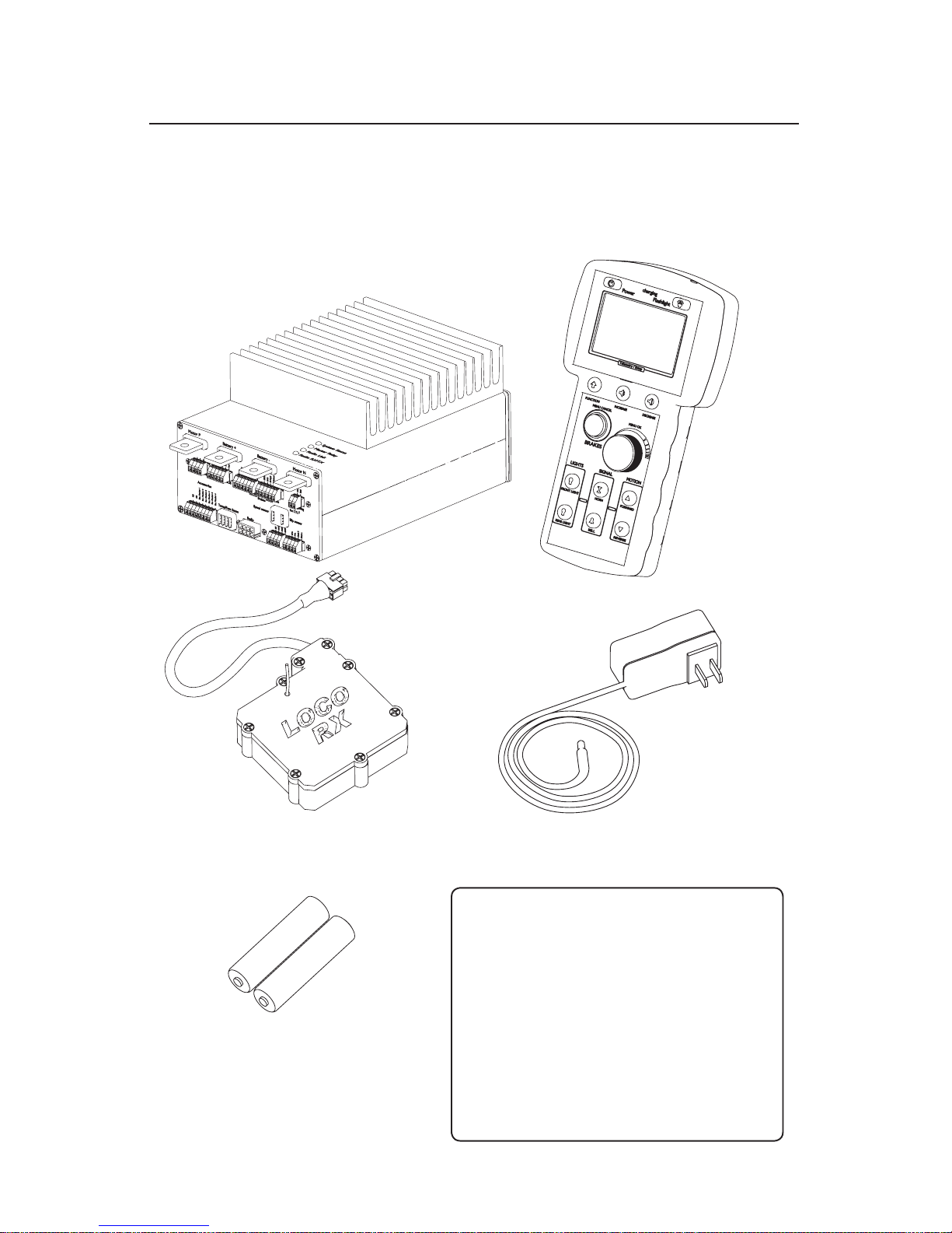
What’s in the box?
LT150A Locomotive control unit
LT150A Remote control Handset
LT150A Radio Tranceiver (picture might
dier, depending if the wire antenna or External
antenna version was ordered)
12V Charger for LT150A Handset With
MU Port Socket
Make sure your box contains everything listed below. If any pieces are missing, contact
the seller.
If this system got delivered pre-built into a locomotive, make sure that these items are
listed by your seller and nothing is missing.
Set of AA Rechargeable Batteries
Additional Items:
1. Bag of Phoenix connectors ( 1x 8pin, 2x
6pin, 1x 5pin, 3x 4pin, 1x 2 pin)
2. MU Rear Port Cable, for handset charging
3. This manual
4.(optional) Ballast resistors for LED lighting
5.(optional) Radio Tranceiver Extension Cord
Page 6
6
PRELIMINARY
D
U
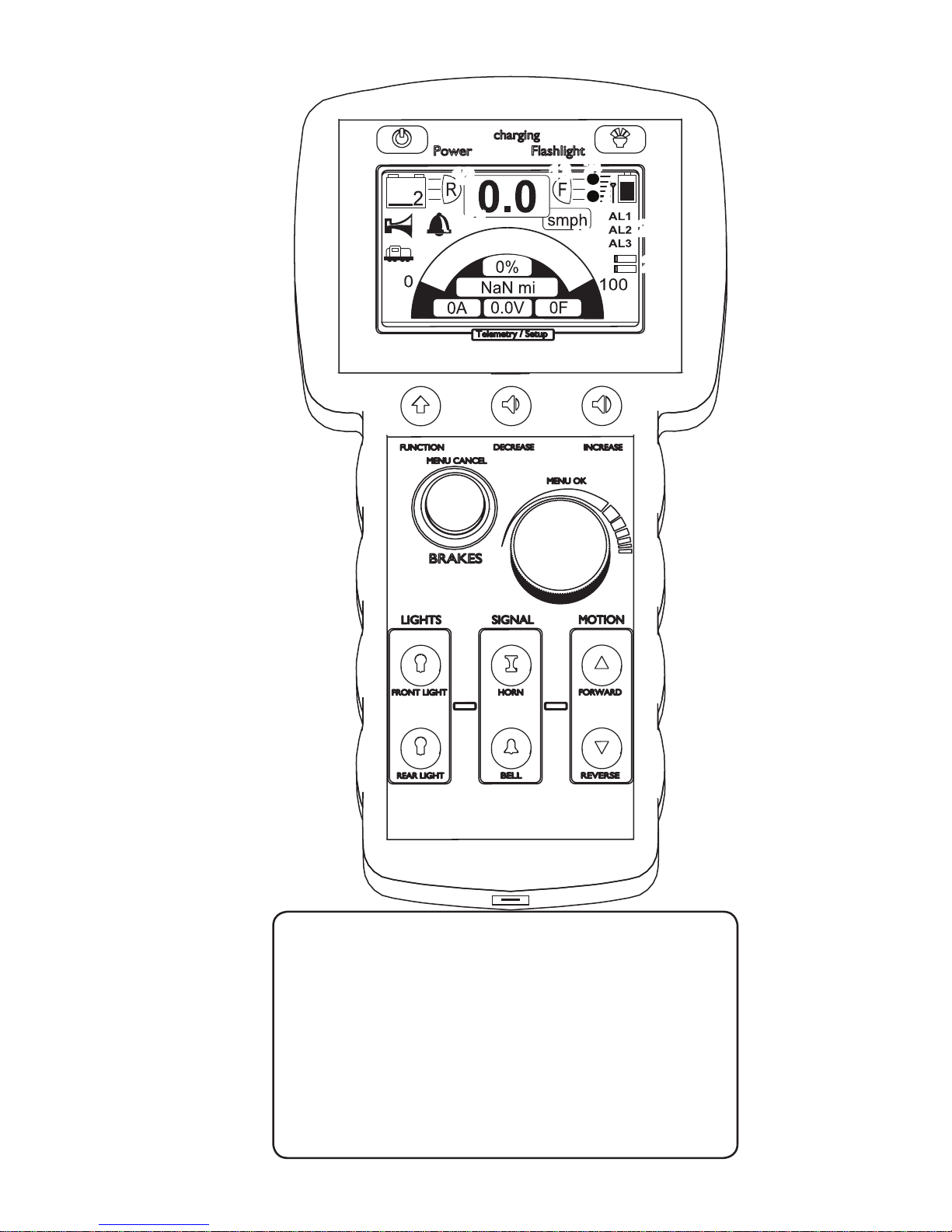
1a. THE LT150A HANDSET
1. Main Display
2. Power Button
3. Flashlight button
4. Light buttons
5. Horn button
6. Bell button
7. Forward button
8. Reverse button
9. Charging indicator
10. Locomotive Battery
Indicator
11. Remote Battery Indicator
12. Rear light Indicator
13. Front light indicator
14. Speed/PSI indicator
15. Speed format indicator
16. reverse indicator
17. forward indicator
18. brake button
19. control Knob
20. Charging port
21. Function button
22. Volume up
23. Volume down
24. Ditch Light Indicator
25. Signal Strength indicator
26. Data Load Meters
(Down and upstream)
27. Aux Panel
20
1.
2
3
4
5
6
7
8
9
10
11
12
14
15
16 17
18
19
21
22
23
13
25
26
24
27
Page 7
7
PRELIMINARY
2. Handset - Before rst use
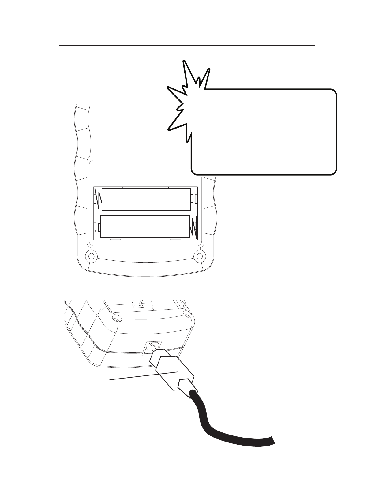
Inserting the rechargeable batteries into the handset.
!
Charging the handset batteries
The handset can also be operated
with 2 regular AA Alkaline batteries.
However, the internal charger will only
work with rechargeable batteries.
WARNING: Do not attempt to use
the charger with alkaline batteries
installed!
+
-
To charge the handset batteries, plug the
charger into the receptactle on the bottom
of the handset.
The LED on the front face of the handset
marked “charging” will indicate the charging mode and status. How the codes for
charging are read is described on page 8.
Charging
Cable
+
-
Page 8
8
PRELIMINARY
D
U
Press and hold the power button for a seconds.
You will see the splash-screen before the handset shows the main dashboard. The handset is
now ready to use
Turning the handset on.
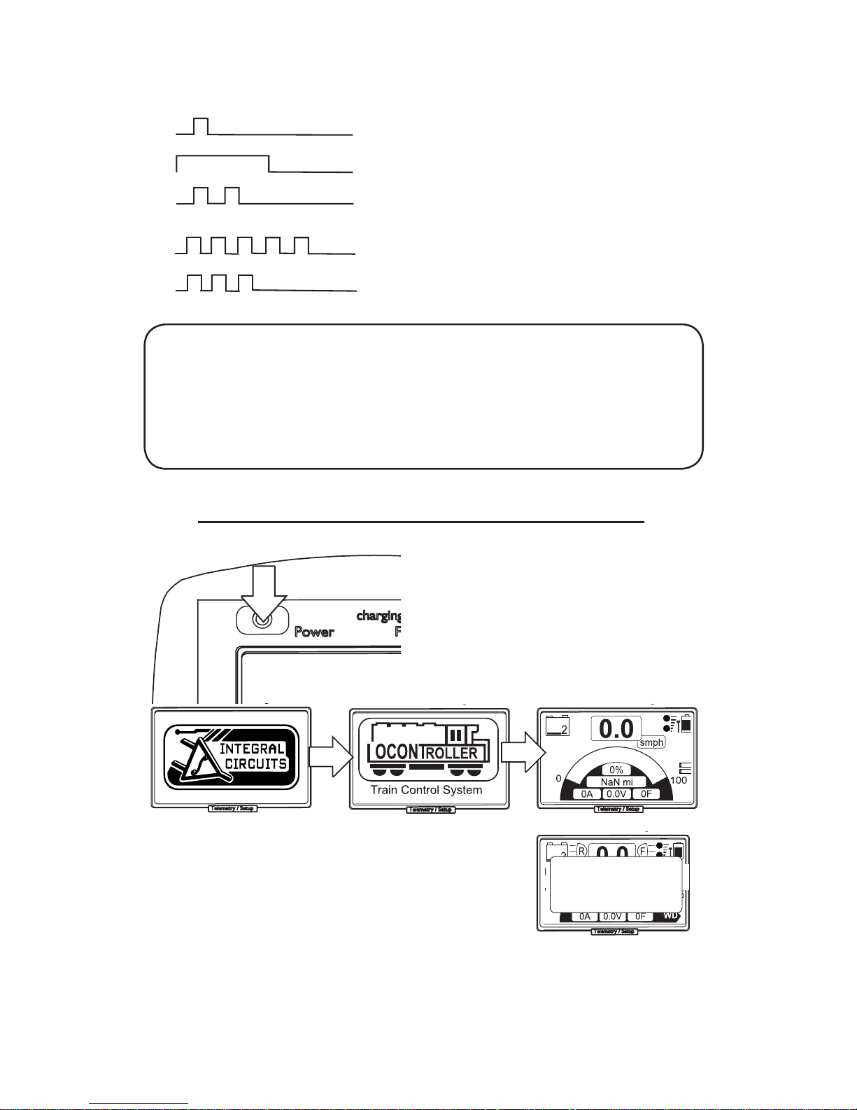
Charger LED indicator codes:
Code:
Pre charge state - 1 short ash per second
Rapid Charge - led is equally on/o per sec
Post charge - led ashes short twice
No battery detected - 5 short pulses
Post charge constant voltage mode - 3
short ashes
During charging, if the battery is deeply discharged, the charger will indicate it is in a “pre-charge” state in which the battery voltage is brought up to
approximately .8V per cell before commencing rapid charge.
If the batterys are at .8V per cell or above, the charger will enter rapid
charge mode in which the batteries are charged at 500mA for a maximum
time of 5 hours
Please note: The charger will not start rapid charging the batteries if they are still more than 50% charged.
Turning the handset o.
To turn the handset o you have to press and hold the power button for another 2 - 3
seconds until it shows “info shutdown”
D
U
D
U
D
U
NO LOCO!
couldn’t nd loco
Turn on loco power!
When the locomotive is not turned on within 10
to 15 seconds the Handset will Time-out and
show that it can’t nd the locomotive.
Turn the locomotive on, and then press the
brake button once it is running. The message
will disappear and the system is ready.
No Link To locomotive.
Page 9
9
PRELIMINARY
3. System startup procedure
1. Turn on the handset by pressing the power button for 2
seconds
2. Turn the Key switch on your locomotive to ON. Position.
3. The LT150 A will go through a startup sequence.
4. When all system checks are done and turn out OK, it will start
ashing the system LED indicator while the Master Relay led will
become lit solid
4.a The Locomotive Link symbol (on left of screen) will show up
5. press the brake button on the handset until the system LED
lights up solid . System, Master Relay and Radio link should be
solid
Startup Error Messages:
These error messages appear if any of the system checks at startup return a
negative result.
The controller will check for battery voltage and motor drive/motor health, before
it unlocks the system for use
Low locomotive battery error:
Symptom: Solution:
Battery voltage shows 0 Check the wire and fuse for the battery monitors
Battery voltage is ~ 22V 24V sys Locomotive batteries need recharged.
Battery voltage is ~ 33V 36V sys Locomotive batteries need recharged.
Motor test failed error:
Symptom: Solution:
Motor short detected! Check the wiring of the motors for shorts.
Check the motors directly for shorts.
Startup:
1.
2.
3.
4.
5.
all initially o
press
D
U
LOCO BATTERY LOW
Low Battery Voltage: 0.02V
D
U
MOTOR TEST FAILED
Motor short detected!
D
U
D
U
0A
25.0V 78F
Dashboard lls with Telemetry.
Locomotive Link symbol appears(left)
3 Leds Solid
Page 10
10
PRELIMINARY
D
U
OVERHEAT!
Motor controller overheat!
turn o system for cooldown!
D
U
E-STOP
User E-STOP triggered
push brake to reset
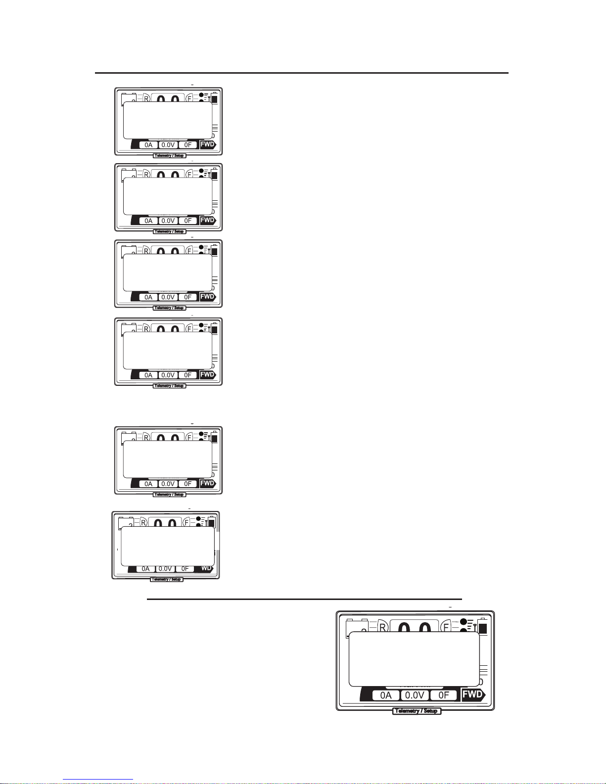
4. System and Error Messages
User E-STOP:
This message shows when the power button is pressed while the
system is in operation.
It indicates that the locomotive entered the emergency stop state.
This can be cancelled with a push of the brake button.
Dropped handset E-STOP:
This message shows whenever the handset is dropped and been in
freefall for longer than the period specied in the setup menu. (“fall
time” page 17.)
Handset battery low warning:
This message shows whenever the batteries of the handset fall below
a charge voltage of 1.9v . This message is only shown for a short mo-
ment before the handset turns itself o. (safety shutdown)
Immediate recharging of the Handset batteries is adviced.
Overcurrent Warning:
The system triggers this message whenever the internal current limit of
approximately 175A is overstepped. This is a safety feature to prevent
damages to the motor or motor drive due to mechanical blockage or
overburdening of the locomotive.
Please note that the locomotive wont stop when this occurs, but the
internal safety will turn o the drive on a per PWM cycle basis, and
limiting the current.
To dismiss this message you need to rotate the knob of the handset a notch.
Overheat E-STOP:
The system triggers an Cycle STOP whenever the internal temperature
sensors measure a tamperature above the safe zone for the internal
components.
This message can not be dismissed until the locomotive and handset have been power cycled
System cool down before further use is adviced!
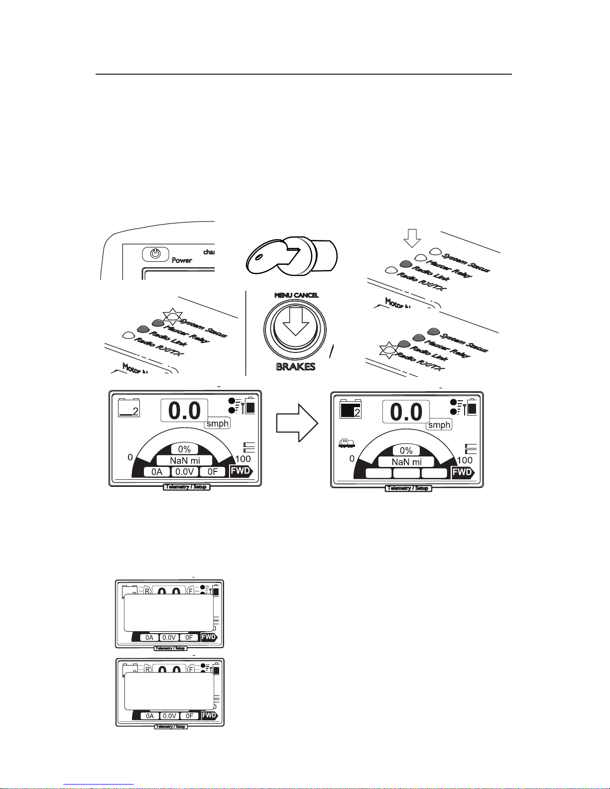
User Induced E-STOP:
If you press the power button at any given time
the locomotive will go into an User requested
E-Stop. To cancel this you need to push the
brake - button once.
D
U
E-STOP
User E-STOP triggered
push brake to reset
D
U
E-STOP
TX dropped!
push brake to reset
D
U
TX Battery Low!
shutting down handset..
D
U
Overcurrent!
Current above 175A
reduce speed to continue
D
U
LINK LOSS!
Link to locomotive lost
Check Locomotive power
LINK LOSS!:
The Remote is not receiving any telemetry or heart-beat signal from
the locomotive. This can be the result of a bad reception, out of signal
range or loss of power in the locomotive.
This message can be dismissed with the push of the brake-button.
However, it will come back until the link to the locomotive has
been re-established.
Page 11
11
PRELIMINARY
D
U
0A
25.0V 78F
10%
D
U
0A
25.0V 78F
80%
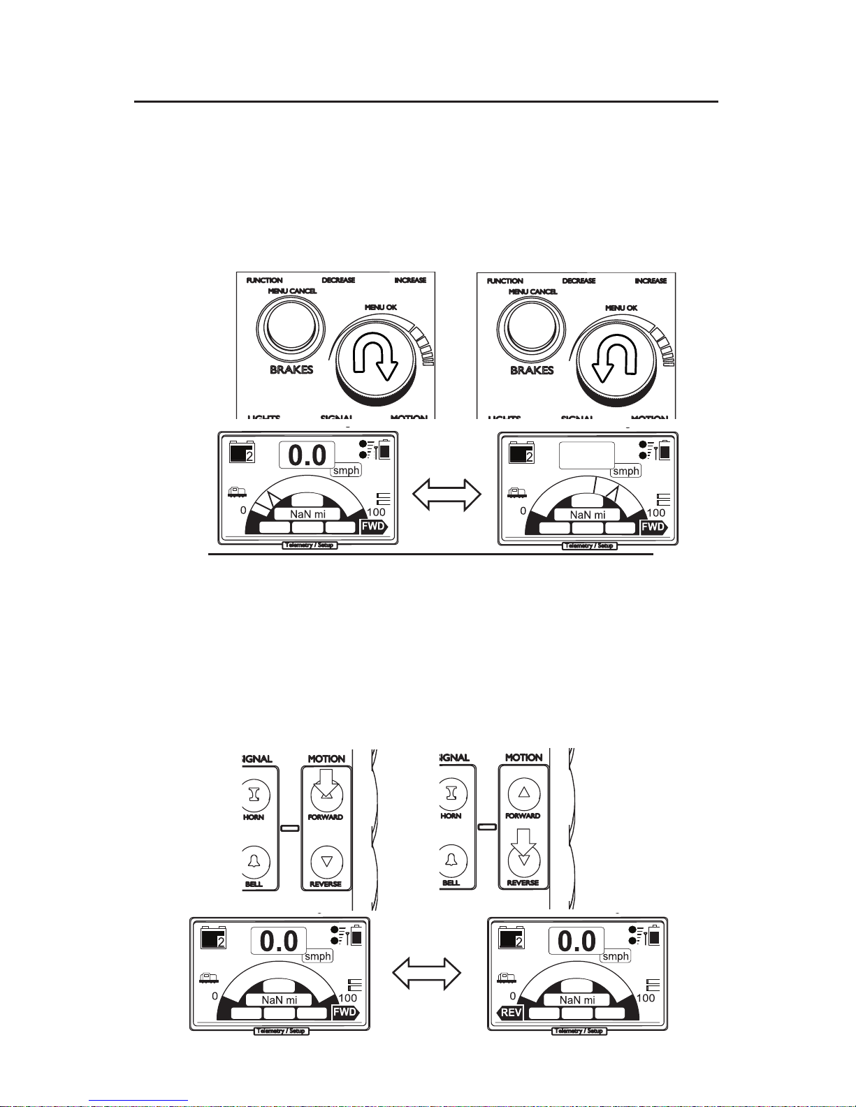
5. Control of your locomotive
Setting speed:
Make sure the brakes or brake lock are not active.
1. Turn the knob clockwise to increase speed.
2. turn the knob counter clockwise to decrease speed.
1.
2.
Changing direction:
1. press ‘forward’ to change the direction to forward
travel
2. press ‘reverse’ to change the direction to backward
travel.
Depending on the setting of reverse limit in the
Setup menu (page 18). you can change the direction
into the opposite way of travel while the locomotive
is throttled up. It will slow down and then reverse
into the opposite direction
1.
2.
7.8
D
U
0A
25.0V 78F
D
U
0A
25.0V 78F
0% 0%
Page 12

12
PRELIMINARY
Applying brakes: (With brake controller, or custom air-brakes installed)
1. Press and hold the brake button. Throttle will be automatically reduced to 0% and brake pressure applied
at the set value. (factory setting is 25psi)
2. Rotate the knob clockwise to increase pressure.
3. Rotate the knob counter clockwise to decrease pressure.
Stopping/slow down:(Without brake controller)
1. Press the Brake button. Throttle will be reduced to 0%.
The four quadrant motor drive of the LT150A will slow
down the locomotive to a stop on an even surface.
if you are on an inclined track piece , the locomotive
might continue to slowly creep forward or backward
down the track. You can prevent this by giving a little
bit of throttle in the opposite direction of travel
Warning! This method is
only useful for short stops.
DON’T
keep the locomotive
throttled up stationary on an
inclined track piece for too
long. It can cause heat damage to your motors!!
press
+
hold
1.
2.
3.
press
1.
!
D
U
D
U
15
15
D
U
D
U
27
26
Page 13

13
PRELIMINARY
Locking brakes: (With brake controller, or custom air-brakes installed)
1. Press and hold the Brake button.
2. Press knob.
3. Release both brake button and knob.
The brake button will light up, indicating that the brakelock mode is now active
Unlocking brakes: (With brake controller, or custom air-brakes installed)
1. Press and hold the Brake button.
2. Press knob.
3. Release both brake button and knob.
The brake button light will turn o, indicating that the
brake-lock mode is now inactive.
Note: Without brake - controller, this function does only maintain a
throttle value of 0. The locomotive might still creep on an inclined
track piece.
press
+
hold
1.
2.
3.
brake LED lights up
press
+
hold
1.
2.
3.
brake LED turns o
press
press
Checking locomotive battery voltages
This function does not work
in Brake Lock mode
1. Press the knob while not in brake-lock mode. The display switches from showing the regular dash to a screen
showing the voltages of the locomotive batteries.
1.
!
D
U
0A
24.4V 78F
0%
Page 14

14
PRELIMINARY
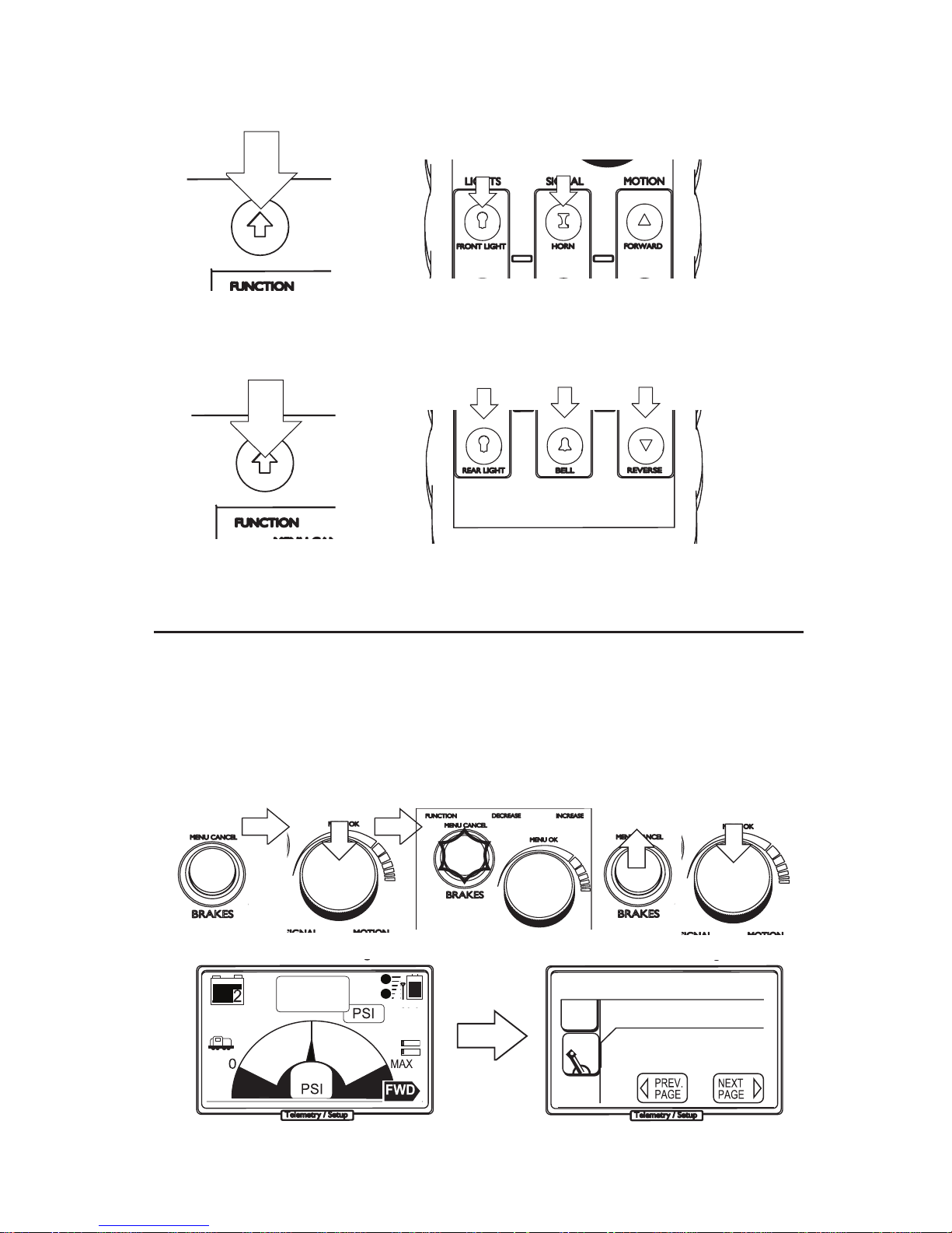
Turning on the front light
Sounding the horn
Turning the bell on and o
1. Press the front light button
2. Once the front light is on, you may dim it by pressing
the button again. It will toggle back and forth between
bright and dim setting.
3. To turn the front light o, press and hold the button
until the front light symbol on the LCD disappears and
the front-light turns o.
1. Press the “bell” button. This will turn the bell pulse
signal on and will repeat until you turn the bell o again.*
2. Press the button again to turn the bell signal o.*
1. Press the “horn” button, the horn should blow and
keep blowing as long as you keep the button pressed. It
will turn o as soon as you release the button*
Turning on the rear light
1. Press the rear light button
2. Once the rear light is on, you may dim it by pressing
the button again. It will toggle back and forth between
bright and dim setting.
3. To turn the rear light o, press and hold the button
until the rear light symbol on the LCD disappears and the
rear-light turns o.
* Please note that both functions (horn and bell) are
bound to the installed sound-module. And depending on
what module was used, there might be a slight lag of response (we use Econami,Tsunami or Loksound modules,
depending on customer order)
Page 15
15
PRELIMINARY
Entering the Setup Menu:
1. Press and hold the brake button.
2. With the brake button held, press the knob.
3. release both brake button and knob. The red LED on
the brake button will be lit (brake lock mode see page 9.)
4. Now press and hold the knob for a few seconds.
until the handset enters the setup menu.
6. Setup Menu
1.
2.
3.
brake LED lights up
press &
hold 3-4sec.
release
press
4.
5.
press
+
hold
D
U
D
U
15
15
D
U
D
U
Handset Setup 10
Throttle Resolution
25
clicks
1
2
4
5
3
Aux channel:
Press and hold press any of the Aux buttons
Aux1 Aux2 Aux3
Ditch Lights
Press and hold
Ditch On/o Ditch Flash
You can change the menu page via ‘increase’ and ‘decrease’ buttons
Page 16
16
PRELIMINARY
D
U
D
U
Handset Setup 10
Throttle Resolution
34
clicks
1
2
4
5
3
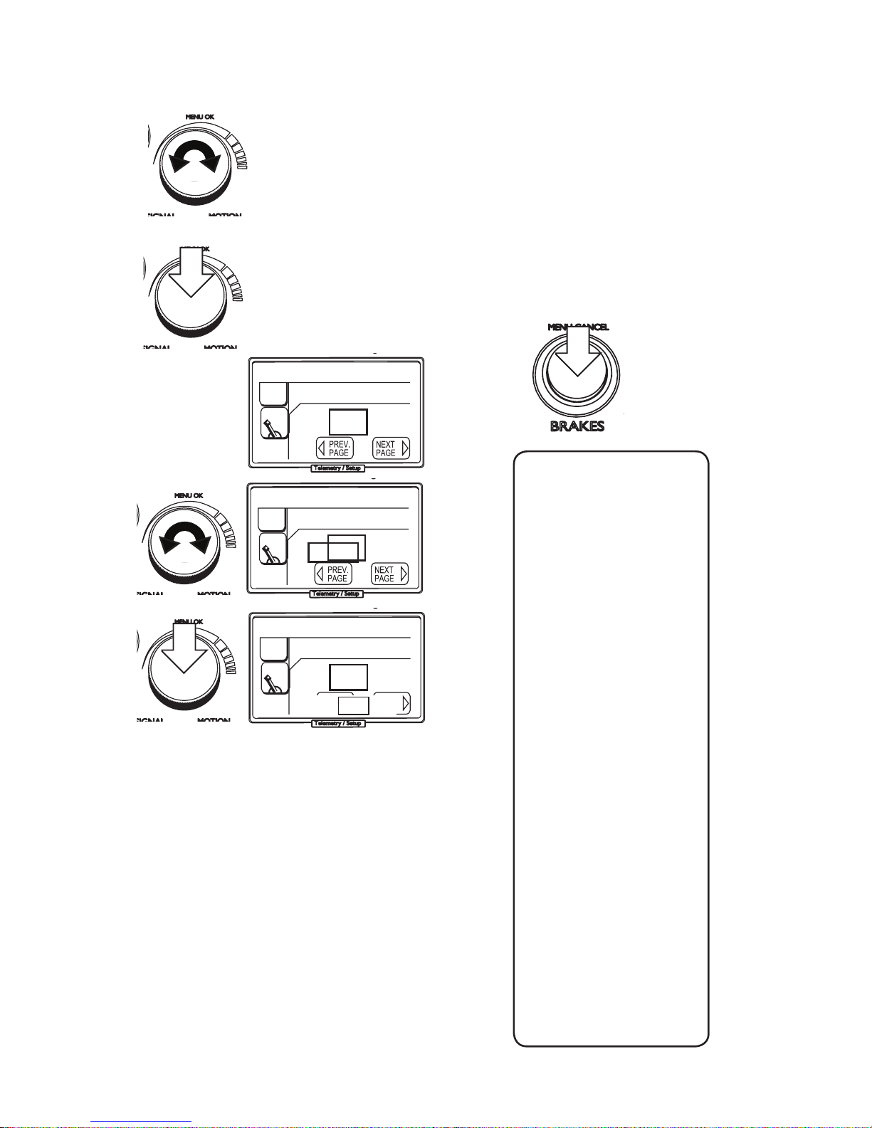
Changing menu settings.
1. Use the knob to choose which menu setting you want to
change.
2. Press the knob to change the currently selected setting.
3. A rectangle will appear around the value.
4. Now use the knob to change the value.
5. Press the knob again and the menu will ask you if you want
to save: Yes = save change. No = dismiss change.
6. Press the brake button (menu cancel) at any time and the
handset will return to the dash in brake-lock mode. You can
re-enter the menu by just holding down the knob again for a
moment.
List of available settings:
Throttle Resolution
Backlight on/off
Dead manTimeout
Speed Format
Drop Sensor
Autoreverse Limit
Maximum Speed
DefaultBrake PSI
Max Brake PSI
Acceleration
Deceleration
Wheel diameter
Electric or Gasoline
Battery Count
Load Current Gain
Sensor Input 1
Sensor Input 2
Sensor Input 3
Sensor Input 4
Front Light Level
Rear Light Level
Ditchlight time
Lighting System
EStop deceleration
EStop Brake Pressure
Front light Dim
Rear Light Dim
Brake Prsr. deadband
Brake Prsr. offset
Current gain
Current offset
ADC Calibration
Temp Calibration
Sound prole
Rung 1
Rung 2
Rung 3
Rung 4
Rung 5
Rung 6
Rung 7
Rung 8
press to exit
D
U
D
U
Handset Setup 10
Throttle Resolution
25
clicks
1
2
4
5
3
Save? YES NO
1.
2.
3.
4.
5.
6.
press
press
D
U
D
U
Handset Setup 10
Throttle Resolution
34
clicks
1
2
4
5
3
Page 17

17
PRELIMINARY
Sets the amount of clicks on the encoder it takes to get to full 100% of
throttle
Sets the backlight to either On (fade mode) or o (stays o)
Sets the time it takes for the deadman to stop the locomotive when no
input is received, in seconds
Sets the format the system shows speed and distance.
Sets the sensitivity of the accelerometer inside the handset. This is the
amount of time the handset has to be in free-fall before it E-stops
Sets the threshhold for the autoreverse limit. The locomotive can be
reversed, as long as it is not throttled up beyond this limit.
Sets the maximum available throttle that can be set. Limits the maximum
speed of the locomotive.
Sets the default brake pressure that is available upon system start. This is
also the setting the Emergency stop feature uses by default.
Sets the absolute maximum brake pressure the system can reach.
Sets the acceleration behavior of the locomotive (how fast or slow it accelerates) in percent per second . a higher value means a faster acceleration
Set the deceleration behavior of the locmotive (how fast or slow it decelerates) in percent per second. a higher value means a faster stop
Sets the wheel diameter of your locomotive. This is needed for correct
speed calculation via speed-sensor input. If you use the sensor on a ywheel (before a reduction occours) you need to divide your wheel diameter
by that reduction and set it accordingly. (5” wheel 1:2 reduction = 2.5”)
reserved setting. no function currently
Sets the amount of batteries in the system. This is needed to correctly
calculate voltages and battery levels.
Sets the gain for the sound module’s rung calculation. at high loads the
engine will sound more tasked.
Can be set either to fuse input (fuse detection) or Temperature sensor.
(This feature is currently only implemented but not enabled)
Sets the global brightness of the front lights. Dim will be calculated from
this too. (about half)
Sets the global brightness of the rear lights. Dim will be calculated from
this too (about half)
Determines how long the ditchlights keep ashing when triggered
Selects the type of lighting system and system voltage.
Incandescent 24 or 36V
1 LED per channel @ 24 or 36 v
2 LED per channel @ 24 or 36V
(continued on page 18)
Handset setup:
Throttle Resolution
(range 8-100)
Backlight on/off
(range on/off)
Deadman Timeout
(0-30 seconds)
Speed Format
(mph/smph/kph/skph)
Drop sensor
(5-100ms)
Auto-reverse Limit
(1-50%)
Locomotive setup:
Maximum Speed
(10-100%)
Default Brake Prsr.
(0-50psi)
Maximum Brake Prsr.
(10-80psi)
Acceleration
(1-50%/s)
Deceleration
(1-50%/s)
Wheel diameter
(1.000 to 8.000 inch)
Electric or Gasoline
Battery Count
(2-6 bat)
Load Current Gain
(1-20)
Sensor input 1 to 4
Front Light Level
(0-15)
Rear Light Level
(0-15)
Ditchlight time
Lighting System
Description of functions:
Page 18

18
PRELIMINARY
Description of functions (cont):
Sets the deceleration for the Emergency stop situation. This setting allows
for a rapid deceleration without stoping the locomotive too hard.
Sets the pressure that is used in an Emergency Stop.
Sets the Dim-level of the front light
Sets the Dim-level of the rear light
*These are Factory Calibrations that we set before shipping of the unit and
usually do not ned to be changed manually*
Sets the deadband of the brake pressure sensor. Default is 1PSI
Sets the voltage oset for the pressure sensor in use. The oset voltage
can be found in the datasheet of most pressure sensors.
by default this is set to a MPX5500 pressure sensor oset voltage
Sets the scale multiplier for the current gain
Sets the voltage oset of the current sensor in use.
Sets the multiplier for the Analog to Digital converter inside the Unit
Sets the Compensation value for the internal Temperature sensors
Sets dierent proles which distribute the rungs being send to the
sound module at dierent positions of the speed gauge. This is mainly
used to match the various dierent sound modules available.
Sets the amount of throttle where Rung 1 will be triggered
Sets the amount of throttle where Rung 2 will be triggered
Sets the amount of throttle where Rung 3 will be triggered
Sets the amount of throttle where Rung 4 will be triggered
Sets the amount of throttle where Rung 5 will be triggered
Sets the amount of throttle where Rung 6 will be triggered
Sets the amount of throttle where Rung 7 will be triggered
Sets the amount of throttle where Rung 8 will be triggered
Loco Setup(Cont):
EStop deceleration
EStop Brake PSI
Front light Dim
Rear Light Dim
Calibration Setup:
Brake Prsr.
deadband
Brake Prsr. offset
Current gain
Current offset
ADC Calibration
Temp Calibration
Sound Setup:
Prole
Rung 1
Rung 2
Rung 3
Rung 4
Rung 5
Rung 6
Rung 7
Rung 8
Page 19

19
PRELIMINARY
The Event System:
The event system gives the ability to assign functions of the
locomotive controller to certain events happening during
operation. At default the front and rear headlight are assigned
for dimming operation on direction change. The ditchlights are
assigned to the horn trigger.
Events
On Forward
On Reverse
On Brake
On B.Lock
On Horn
A1 A2 A3 FL RL DL
o = dim= on=
Selecting a Event:
1.
1. Use the knob to select the event on the grid you want to modify
2. press the knob
3. a menu will pop up that shows the dierent settings you can
choose.
4. select the setting and press the knob again. The event is now
assigned.
no action = nothing will happen, all functions remain as they
were
on = the selected channel will turn on with the event and o
again when the event is over.
o = the selected channel will be always on and only turns o
with the event happening, same as the on state but inverted.
dim = only used for the headlights, choose if the lights dim on
direction change or not.
2.
press
Events
On Forward
On Reverse
On Brake
On B.Lock
On Horn
A1 A2 A3 FL RL DL
o = dim= on=
no action
on
o
dim
3.
Page 20
20
PRELIMINARY
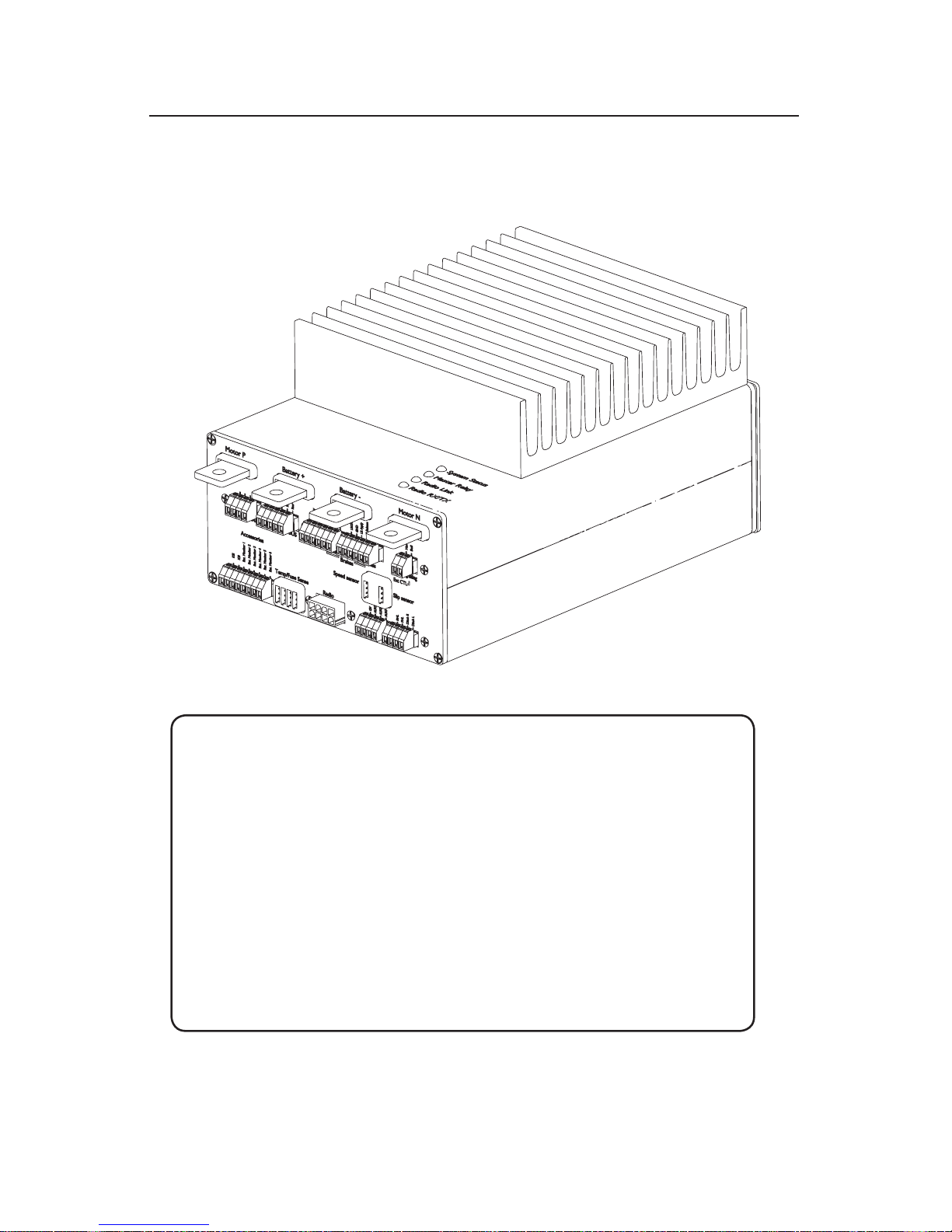
7. The LT150A (hardware setup)
1
2
3
4
5
6
7
8
9
10
11
12
13
14
1. System Connector
2. Lights / Aux Connectors
3. Radio Connector
4. Handset charge /
Mu connector
5. Loco Brakes connector
6. Train Brakes connector
7. Speed sensor input
8. Fuse sensor input
9. System LED panel
10. Positive Motor Lug
11. Negative Motor Lug
12. Positive Battery Lug
13. Negative Battery Lug(GND)
14. Heatsink
-
connector connections
Parts of the LT150A
Page 21

21
PRELIMINARY
7a. Front panel Pinout
Page 22

22
PRELIMINARY
Page 23

23
PRELIMINARY
Page 24

24
PRELIMINARY
Installing the radio Tranceiver
When you install the tranceiver you need to make
sure that the antenna is clear of any obstructions
1. 8pin radio tranceiver plug
2. Radio antenna
3. Activity / Connection LED (on backside)
!
Plug the radio tranceiver into the 8 pin receptacle on the frontpanel of the LT150A controller
1
2
3
Page 25

25
PRELIMINARY
Installing the system connector
Plug the 8 pin Phoenix plug into the system monitor receptacle
The pinout for this connector is as described here:
KSI and the battery monitors are absolutely mandatory for operation of the unit!
!
Key switch input (KSI)
This connection should be fused
with a 3A Fuse (minimum)
(mandatory connection)
Battery monitors
Bat Type: 6v 12v
Bat1 6v 12v
Bat2 12v 24v
Bat3 18v 36v
Bat4 24v
Bat5 30v
Bat6 36v
Battery Monitor connections
should be fused with a 0.5A
fuse (minimum)
Page 26

26
PRELIMINARY
Make sure you do not mix the connection shemes up!
The Lighting pins can drive up to 4A (switched ground)
The Aux pins can drive up to _A (switched 12V)
The 12V Pin can drive up to _A
!
Installing the Lights and Aux Connector
Constant 12V
Aux 1 (12V)
Aux 2 (12V)
Aux 3 (12V)
Left Ditchlight
Right Ditchlight
Front Head Light
Rear Head Light
AUX/12V:
Lights:
VCC
LT150A
10/20w
3A Fuse
GND
LT150A
device
Page 27
27
PRELIMINARY
Integral circuits brake controllers come with a ready made control cable or an
attached cable, depending on the model.
Integral circuits brake controllers come with a
ready made control cable or attached cable depending on the model.
!
Installing the Loco brake connector
Plug the 6 pin brake phoenix connector into the Loco brake receptacle.
The pinout for this connector is as described here:
12V
GND
Apply
Release
GND
Pressure Sensor
Page 28

28
PRELIMINARY
Integral circuits brake controllers come with a ready made control cable or an
attached cable, depending on the model.
Integral circuits brake controllers come with a
ready made control cable or attached cable depending on the model.
!
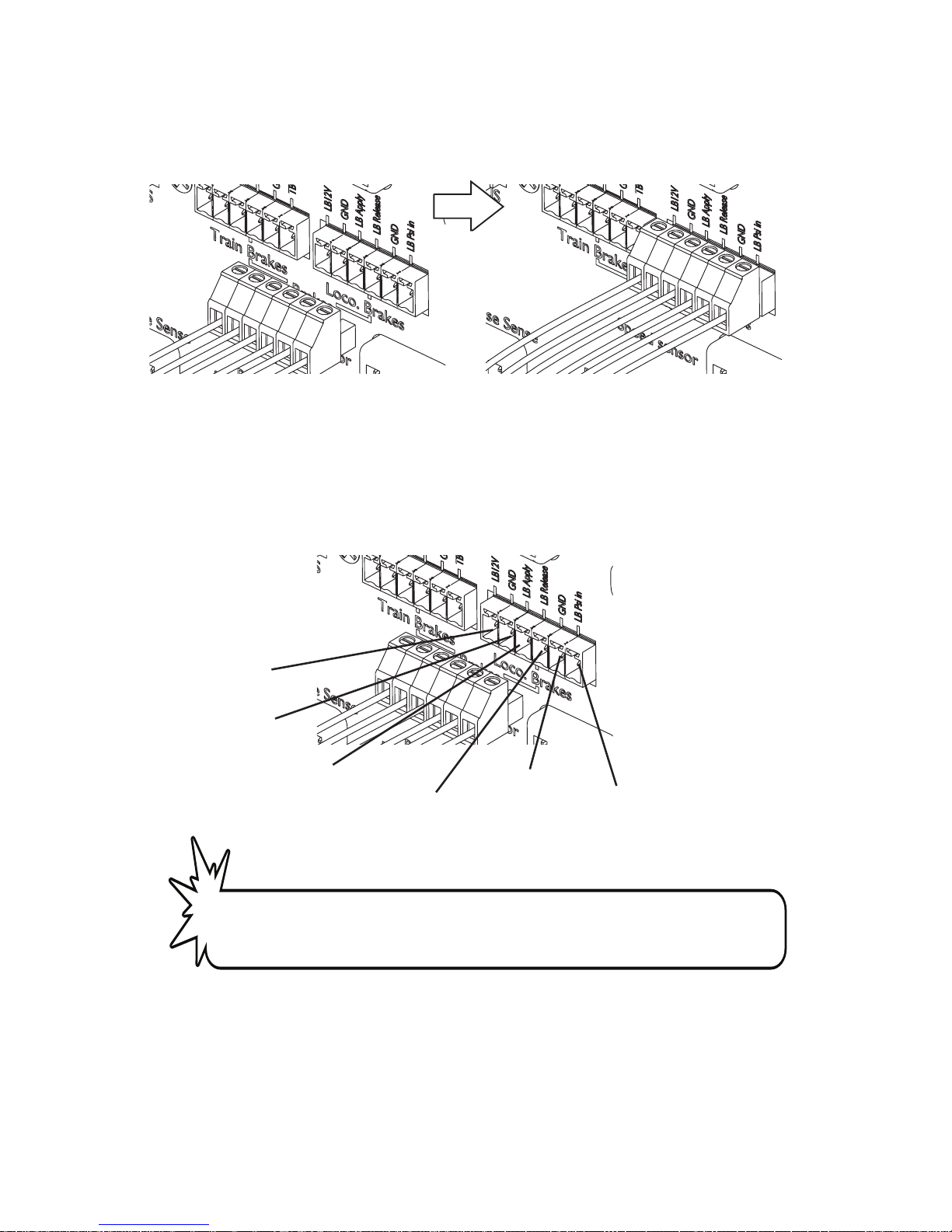
Installing the Train brake connector
Plug the 6 pin brake phoenix connector into the Loco brake receptacle.
The pinout for this connector is as described here:
12V
GND
Apply
Release
GND
Pressure Sensor
Page 29
29
PRELIMINARY
Integral circuits brake controllers come with a ready made control cable or an
attached cable, depending on the model.
The LOCOnTROLLER comes with one pre-made
MU connector for installation in the Locomotive
body
!
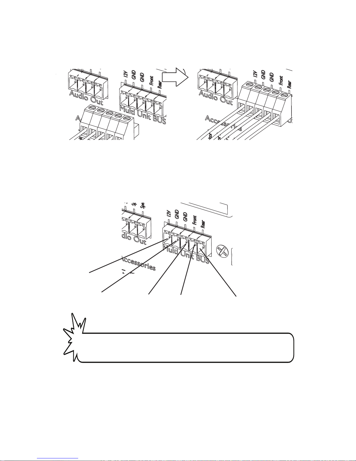
Installing the Multi unit connector
Plug the 6 pin brake phoenix connector into the Loco brake receptacle.
The pinout for this connector is as described here:
12V
GND
GND
Front MU
Rear MU
Page 30

30
PRELIMINARY
Brake controller installation diagram (BC100)
Brake controller installation diagram (BC50)
LT150A
LT150A
Page 31
31
PRELIMINARY
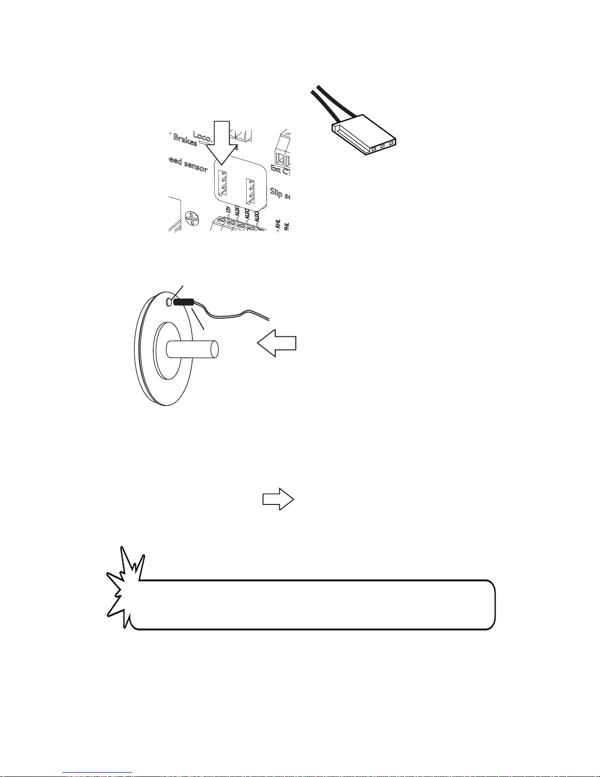
Installing the speed sensor
3 pin futaba servo connector
Sense
Ground
The LT150A needs a pulse signal to ground on
its speed input connection to measure speed.
A simple reed switch and one single magnet on
one of the wheels of the locomotive is sucient
for this.
Magnet
Sensor
Locomotive Wheel
The Handset will show the speed at the top of
the dashboard . The speed is shown in the format you have set in the setup menu “speed format” (mph, smph , kph, skph)
Like in the the example on the left where it shows
the locomotive traveling at 5.4 miles per hour.
Integral circuits brake controllers come with a ready made control cable or an
attached cable, depending on the model.
For this to work right, you need to set the according wheel diameter of your locomotive in the
Setup menu (page 17)
!
Page 32

32
PRELIMINARY
9. Wiring Diagram (provided Externally)
Page 33

33
PRELIMINARY
Page 34

34
PRELIMINARY
Notes
Page 35

Notes
Page 36

©2016 Integral Circuits, LLC.
 Loading...