

Integral Audio MCSS630SW-RAM, MCSS630-RAM Installation Manual

INSTALLATION GUIDE
SOUNDSTAGE + SUBWOOFER SYSTEM
WITH REAR AMP MOUNT (MCSS630SW-RAM) ver. 4/2014
SKILL LEVEL REQUIRED APPLIES TO
DO-IT-YOURSELF
INSTALLATION DIFFICULTY
3 OUT OF 5
INSTALLATION TIME
6-8 HOURS
OVERVIEW ........................................................................................................................................ 2
BEFORE YOU BEGIN .......................................................................................................................... 2
WHAT’S IN THE BOX - SOUNDSTAGE .................................................................................................. 3
WHAT’S IN THE BOX - SUBWOOFER ................................................................................................... 4
TOOLS YOU WILL NEED ...................................................................................................................... 5
INSTALLATION:
A. Prep Vehicle ........................................................................................................................ 6
B. Power & Ground Wiring ........................................................................................................ 7
C. Signal Wiring ....................................................................................................................... 8
D. Amplifier Installation & Speaker wiring...............................................................................9
E. Soundstage speaker installation ....................................................................................... 11
F. Install the Subwoofer [sub only] ........................................................................................ 14
G. Testing & Recommended Initial Settings .......................................................................... 16
TIPS & TUNING ................................................................................................................................ 18
TROUBLESHOOTING ......................................................................................................................... 18
2007+ R56 STANDARD 6 SPEAKER
2007+ R56 HIFI/HK
IMPORTANT
• Read this Guide completely BEFORE you begin.
BEFORE YOU BEGIN
• Disconnect the battery negative terminal while working on the vehicle.
• DO NOT PLACE THE KEY FOB in the vehicle with the battery connected and
the seat airbag wiring disconnected. Doing so will set off the airbag light,
and must be reset by your dealer.
• ALWAYS check behind panels and components before drilling, cutting,
or screwing into any part of a vehicle.
• This guide covers several different vehicle models and options. Some
steps only apply to certain installations. Steps images are labeled with
a black bar across the top:
- [6SPK ONLY]
apply only to vehicles equipped with the standard 6 speaker audio system.
- [HIFI/HK ONLY] apply only to vehicles equipped with the upgraded 10 speaker HIFI and
Harmon Kardon audio system. If the vehicle has tweeters in the A-pillar (near the bottom
outer corners of the windshield), you have the HIFI or HK systems.
- [SUB ONLY] apply only if you are installing the Integral Audio Subwoofer System
- If there is no label, the step applies to ALL installations
- Because each kit applies to more than one vehicle, your kit may include extra items.
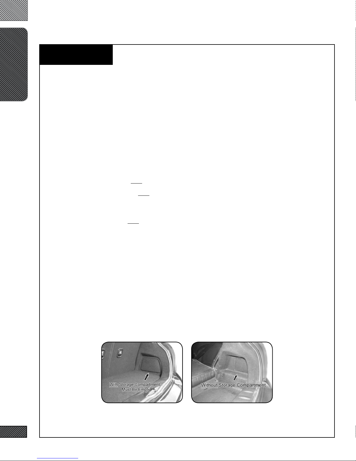
• ARE YOU USING THE CORRECT INSTALL GUIDE? There are two installa-
tion guides: one for installing the amp in the right-rear of the luggage
compartment, the other for installing the amp under one of the front
seats. This guide is for the Rear Amp Mount kit. (All R55, R57, R58,
R59, and ‘07-09 R56 JCW vehicles are Underseat Amp Mount). Compare the passenger side of your vehicles boot area to the images below.
If your vehicle looks like the image on the left, proceed with this installation guide. If not refer to the Underseat Amp Mount Installation
Guide.
Use This guide: Use Underseat Guide:
2

SOUNDSTAGE
WHAT’S IN THE BOX
I. SOUNDSTAGE SPEAKER PACKAGE
1. IASS-T 1” Silk Dome Tweeter (Pair)
2. IASS-4 4” Midrange (Pair)
3. IASS-6 6” Midwoofer (Pair)
II. SOUNDSTAGE CROSSOVER NETWORKS WITH
VEHICLE-SPECIFIC TUNING & EQUALIZATION
4. MCSS630MW Mid-Woofer Network (Pair)
5. MCSS630T Tweeter Network (Pair)
III. ARC AUDIO KS MINI AMPLIFIER (2CH W/
SOUNDSTAGE, 4CH W/SOUNDSTAGE + SUBWOOFER)
IV. SIGNAL & SPEAKER WIRING HARNESSES
6. Signal Wiring Harness (MCWH-SIG-R)
7. Mid-Woofer Connection Harness (Pair)
8. Tweeter Pigtail (Pair)
V. SOUNDSTAGE HARDWARE
9. Midrange Mounting Adapter (Pair)
10. Midwoofer Mounting Adapter (Pair)
11. #8 x 1/2” Midwoofer Mounting Screws (12)
12. #6 x 3/8” Midrange Mounting Screws (12)
13. Integral Audio Logo Badge (Pair)
VI. AMPLIFIER INSTALLATION & WIRING
14. Amplfier Power Wiring Harness (complete)
15. Threadlock Wire Splice Connectors (4) [HIFI/HK ONLY]
16. Threadlock Wire Tap (1)
17. Cable Ties (10)
18. 3M Electrical Tape
VII. AMPLIFIER MOUNTING (REAR AMP MOUNT)
19. Amplifier Mounting Bracket
20. M6 Flange Nut
21. Screw Grommet
22. #8 x ½” Truss Head Screw (1)
23. #6 x 3/8” Pan Head Screw (4)
VIII. FACTORY A-PILLAR TRIM W/TWEETER MOUNTS
3
Continued on the next page . . .
SUBWOOFER
WHAT’S IN THE BOX
IX. MC1101S SUBWOOFER ENCLOSURE
X. SB ACOUSTICS 10” SUBWOOFER
XI. SUBWOOFER COVER PANEL
XII. SUBWOOFER HARDWARE
24. Neutrik Speak-On Terminal & Gasket
25. #10 x 2.5” Pan Head Screw (3)
26. #10 x 1.5” Pan Head Screw (6)
27. ¼” x 1” Hex Head Bolt
28. #10 x 1” Black Pan Head Screw (8)
29. #10 x ¾” Pan Head Screw (8)
30. #4 x ½” Black Flathead Screw (2)
31. Threaded Insert (3)
32. Threaded Insert Installation Wrench
33. Cup Washer (6)
34. Rubber Stand-off (9)
35. Subwoofer Mounting Bracket (2)
36. Rosette Thumbscrew (2)
37. Connection Harness (Sub to Neutrik)
XIII. REMOTE LEVEL CONTROL
38. Integral Audio Remote Level Control
39. 3M VHB Double-Sided Mounting Tape (3in)
26
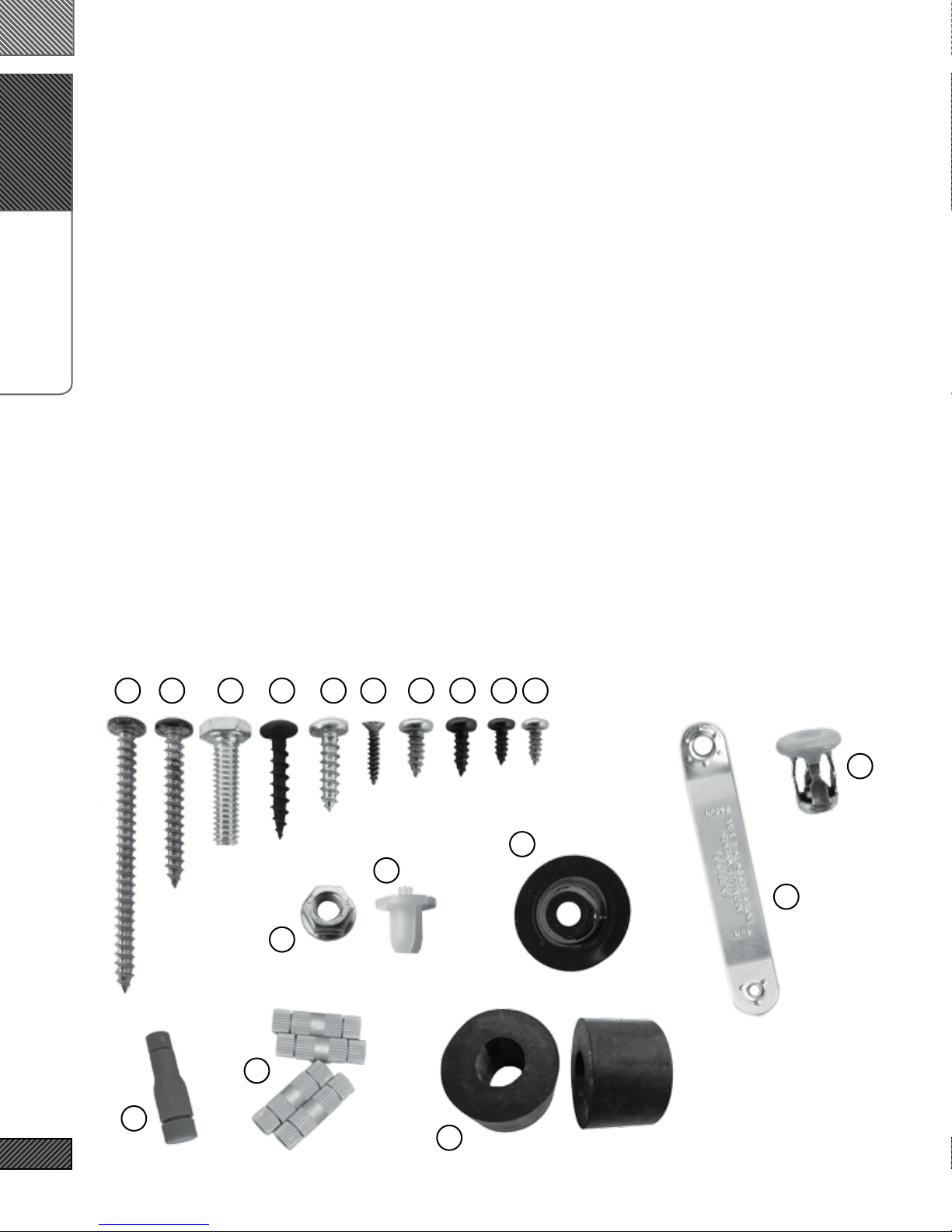
SeSelect Hardware for Identification:
2725 29
20
15
231211223028
31
33
21
32
16
4
34

I. PLASTIC PANEL REMOVAL TOOLS
II. TORX BITS:
1. T25
2. T30
3. T40
4. T50
III. DRILL
IV. DRILL BIT:
TOOLS YOU WILL NEED
5. 7/16” [MUST be correct size!]
V. WRENCHES OR SOCKETS:
6. 7/16”
7. 8mm
8. 10mm
9. 10mm Deep [optional}
10. 19mm
VI. ELECTRICIAN’S WIRE FISH
VII. SCISSORS
VIII. UTILITY KNIFE
IX. PLIERS
X. CENTER PUNCH [SUB ONLY]
XI. WIRE STRIPPER [HIFI/HK ONLY]
XII. PICK & HOOK SET [OPTIONAL]
XIII. MAGNETIC PARTS TRAY [OPTIONAL]
5
Images Not to Scale
A.
PREP VEHICLE
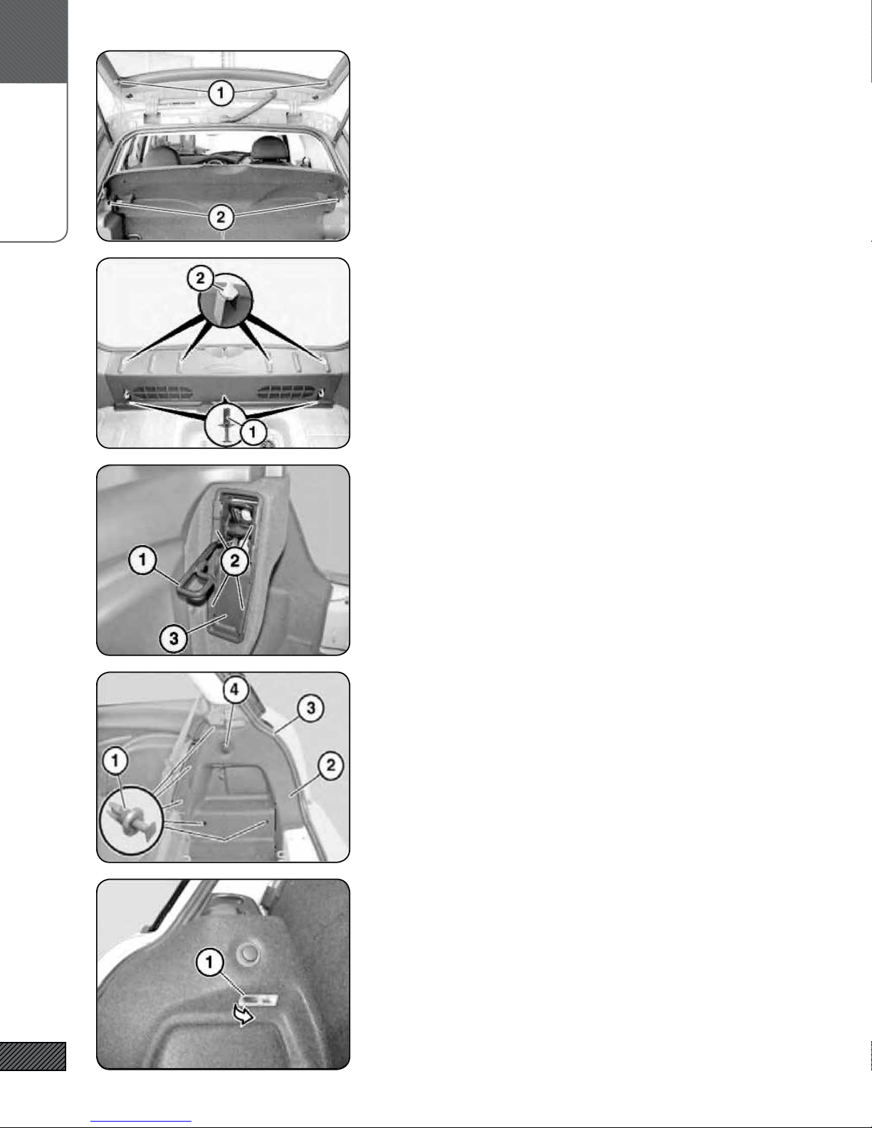
1. REMOVE REAR PARCEL SHELF & FLOOR PANEL
Detach straps (1) and slide the parcel shelf out of guides (2).
Remove the luggage compartment oor panel. The oor panel will
not be placed back into the vehicle and can be stored.
2. REMOVE REAR SILL
Locate the three expansion rivets (1) at the lower edge of the rear
sill. Remove the center-pin of each expansion rivet with a at
screwdriver or panel removal tool. Pry out the base of the expansion rivet. Pull the bottom of the rear sill toward the front of the
vehicle to clear the luggage “D” rings. Pull the whole panel upwards, releasing the friction clips (2). Keep the center-pins with
the expansion rivets to avoid confusion with similar pins removed in later steps.
3. REMOVE RIGHT WHEEL ARCH TRIM (PART 1)
{DOES NOT APPLY TO 2010+] Fold down the rear seats. Lift the
seat catch (1) up halfway. Using a 90 degree pick or other needged tool, pry the retaining clips (2) inwards and upwards to
release them. Remove the trim piece (3).
NOTE: This step can be tedious. If you are careful, you can remove the arch trim without removing this trim piece by angling
the panel and sliding it over the seat catch.
4. REMOVE RIGHT WHEEL ARCH TRIM (PART 2)
Remove the ve expansion rivets (1). Feed out the Wheel Arch
Trim panel (2).
NOTE: When re-installing the panel, make sure to feed the seal (3)
over the top of the edge of the trim panel (2).
6
5. REMOVE LEFT WHEEL ARCH TRIM (PART 1)
Remove the luggage compartment light (1) by prying the rear edge
down and forward. On some vehicles the light may be reversed—
if the rear edge does not release, try the front edge. Unplug the
light.
CAUTION: the light can get quite hot!
A.
PREP VEHICLE
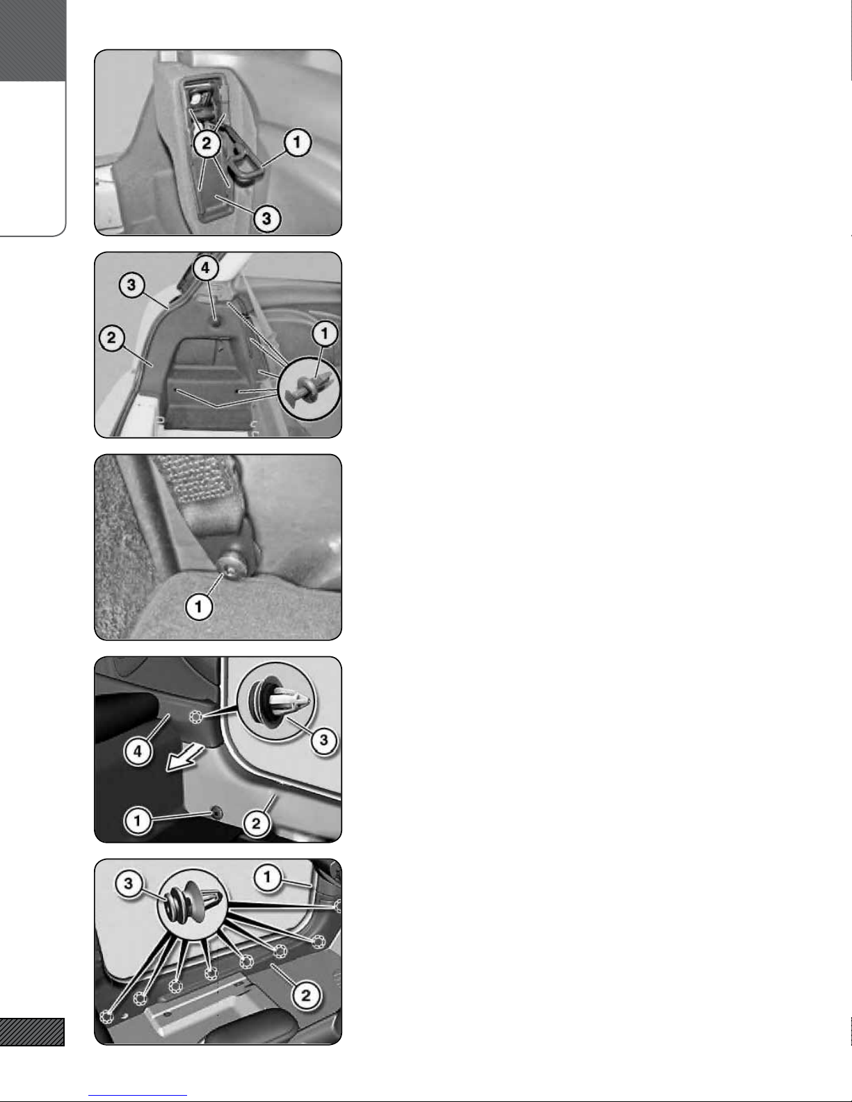
6. REMOVE LEFT WHEEL ARCH TRIM (PART 2)
Same as Right Side. Fold down the rear seats. Lift the seat catch
(1) up halfway. Using a 90 degree pick or other ne-edged tool,
pry the retaining clips (2) inwards and upwards to release them.
Remove the trim piece (3).
7. REMOVE LEFT WHEEL ARCH TRIM (PART 3)
Remove the ve expansion rivets (1). Feed out the Wheel Arch
Trim panel (2). Disconnect the 12V plug (4). NOTE: When reinstalling the panel, make sure to feed the seal (3) over the top of
the edge of the trim panel (2).
Don’t forget to reconnect the 12V plug on reinstall.
8. REMOVE LEFT DOOR SILL TRIM (PART 1)
Using a Torx T-50 bit, remove the seat belt screw (1) where it
passes through the rear of the door sill trim.
9. REMOVE LEFT DOOR SILL TRIM (PART 2)
Remove metal seat belt bushing (1) if not removed in the previous
step. Pull Rear Side Trim Panel (4) in, releasing clip (3) and freeing
tab of Door Sill (2) located behind Side Panel (4).
7
10. REMOVE LEFT DOOR SILL TRIM (PART 3)
[Seat shown removed for clarity]
Remove the door seal over the entire length of the right door sill
by lifting it up and off. Pull up/loosen the rubber door seal gasket along the length of the door. Pull Door Sill Panel (2) inward,
releasing clips (3). This requires a rm pull at each of the clip
locations. Remove the small trim piece (1) by pulling it toward
the rear of the vehicle, releasing spring clip.
 Loading...