

Integral Audio MCSS630MW, MCSS630T Installation Manual

INSTALLATION GUIDE
SOUNDSTAGE + SUBWOOFER SYSTEM
FOR 2013+ BMW 3-SERIES (F30) ver. 5/2016
SKILL LEVEL REQUIRED APPLIES TO
DO-IT-YOURSELF
INSTALLATION DIFFICULTY
3 OUT OF 5
INSTALLATION TIME
4 HOURS
OVERVIEW ........................................................................................................................................ 2
BEFORE YOU BEGIN .......................................................................................................................... 2
WHAT’S IN THE BOX - SOUNDSTAGE .................................................................................................. 3
WHAT’S IN THE BOX - SUBWOOFER ................................................................................................... 4
TOOLS YOU WILL NEED ...................................................................................................................... 5
INSTALLATION:
A. Prep Vehicle ........................................................................................................................ 6
B. Power & Ground Wiring ........................................................................................................7
C. Signal Wiring .......................................................................................................................8
D. Amplifier Installation & Speaker wiring...............................................................................9
E. Soundstage speaker installation ....................................................................................... 11
F. Install the Subwoofer [sub only] ........................................................................................ 14
G. Settings ............................................................................................................................ 16
TIPS & TUNING ................................................................................................................................ 18
TROUBLESHOOTING ......................................................................................................................... 18
2012+ F30 W/O ACTIVE SOUND
DESIGN

IMPORTANT
•Read this Guide completely BEFORE you begin.
BEFORE YOU BEGIN
•Disconnect the battery negative terminal while working on the vehicle.
•DO NOT PLACE THE KEY FOB in the vehicle with the battery connected and
the seat airbag wiring disconnected. Doing so will set off the airbag light,
and must be reset by your dealer.
•ALWAYS check behind panels and components before drilling, cutting,
or screwing into any part of a vehicle.
•This guide covers several different vehicle models and options. Some
steps only apply to certain installations. Steps images are labeled with
a black bar across the top:
- [SUBWOOFER ONLY]
- If there is no label, the step applies to ALL installations
- Because each kit applies to more than one vehicle, your kit may include extra items.
step applies only if you are installing the Integral Audio Subwoofer
System
2

I. SOUNDSTAGE SPEAKER PACKAGE
1. IASS-T 1” Silk Dome Tweeter (Pair)
2. IASS-4 4” Midrange (Pair)
SOUNDSTAGE
3. IASS-6 6” Midwoofer (Pair)
II. SOUNDSTAGE CROSSOVER NETWORKS WITH
VEHICLE-SPECIFIC TUNING & EQUALIZATION
4. MCSS630MW Mid-Woofer Network (Pair)
5. MCSS630T Tweeter Network (Pair)
III. ARC AUDIO KS MINI AMPLIFIER (2CH W/
SOUNDSTAGE, 4CH W/SOUNDSTAGE + SUBWOOFER)
IV. SIGNAL & SPEAKER WIRING HARNESSES
WHAT’S IN THE BOX
6. Signal Wiring Harness (MCWH-SIG-R)
7. Mid-Woofer Connection Harness (Pair)
8. Tweeter Pigtail (Pair)
V. SOUNDSTAGE HARDWARE
9. Midrange Mounting Adapter (Pair)
10. Midwoofer Mounting Adapter (Pair)
11. #8 x 1/2” Midwoofer Mounting Screws (12)
12. #6 x 3/8” Midrange Mounting Screws (12)
13. Integral Audio Logo Badge (Pair)
VI. AMPLIFIER INSTALLATION & WIRING
14. Amplfier Power Wiring Harness (complete)
15. Threadlock Wire Splice Connectors (4) [HIFI/HK ONLY]
16. Threadlock Wire Tap (1)
17. Cable Ties (10)
18. 3M Electrical Tape
VII. AMPLIFIER MOUNTING (REAR AMP MOUNT)
19. Amplifier Mounting Bracket
20. M6 Flange Nut
21. Screw Grommet
22. #8 x ½” Truss Head Screw (1)
23. #6 x 3/8” Pan Head Screw (4)
VIII. FACTORY A-PILLAR TRIM W/TWEETER MOUNTS
3
Continued on the next page . . .

I. SOUNDSTAGE SPEAKER PACKAGE
1. IASS-T 1” Silk Dome Tweeter (Pair)
2. IASS-4 4” Midrange (Pair)
SOUNDSTAGE
3. IASS-6 6” Midwoofer (Pair)
II. SOUNDSTAGE CROSSOVER NETWORKS WITH
VEHICLE-SPECIFIC TUNING & EQUALIZATION
4. MCSS630MW Mid-Woofer Network (Pair)
5. MCSS630T Tweeter Network (Pair)
III. ARC AUDIO KS MINI AMPLIFIER (2CH W/
SOUNDSTAGE, 4CH W/SOUNDSTAGE + SUBWOOFER)
IV. SIGNAL & SPEAKER WIRING HARNESSES
WHAT’S IN THE BOX
6. Signal Wiring Harness (MCWH-SIG-R)
7. Mid-Woofer Connection Harness (Pair)
8. Tweeter Pigtail (Pair)
V. SOUNDSTAGE HARDWARE
9. Midrange Mounting Adapter (Pair)
10. Midwoofer Mounting Adapter (Pair)
11. #8 x 1/2” Midwoofer Mounting Screws (12)
12. #6 x 3/8” Midrange Mounting Screws (12)
13. Integral Audio Logo Badge (Pair)
VI. AMPLIFIER INSTALLATION & WIRING
14. Amplfier Power Wiring Harness (complete)
15. Threadlock Wire Splice Connectors (4) [HIFI/HK ONLY]
16. Threadlock Wire Tap (1)
17. Cable Ties (10)
18. 3M Electrical Tape
VII. AMPLIFIER MOUNTING (REAR AMP MOUNT)
19. Amplifier Mounting Bracket
20. M6 Flange Nut
21. Screw Grommet
22. #8 x ½” Truss Head Screw (1)
23. #6 x 3/8” Pan Head Screw (4)
VIII. FACTORY A-PILLAR TRIM W/TWEETER MOUNTS
4
Continued on the next page . . .
IX. MC1101S SUBWOOFER ENCLOSURE
X. SB ACOUSTICS 10” SUBWOOFER
XI. SUBWOOFER COVER PANEL
XII. SUBWOOFER HARDWARE
SUBWOOFER
WHAT’S IN THE BOX
24. Neutrik Speak-On Terminal & Gasket
25. #10 x 2.5” Pan Head Screw (3)
26. #10 x 1.5” Pan Head Screw (6)
27. ¼” x 1” Hex Head Bolt
28. #10 x 1” Black Pan Head Screw (8)
29. #10 x ¾” Pan Head Screw (8)
30. #4 x ½” Black Flathead Screw (2)
31. Threaded Insert (3)
32. Threaded Insert Installation Wrench
33. Cup Washer (6)
34. Rubber Stand-off (9)
35. Subwoofer Mounting Bracket (2)
36. Rosette Thumbscrew (2)
37. Connection Harness (Sub to Neutrik)
XIII. REMOTE LEVEL CONTROL
38. Integral Audio Remote Level Control
39. 3M VHB Double-Sided Mounting Tape (3in)
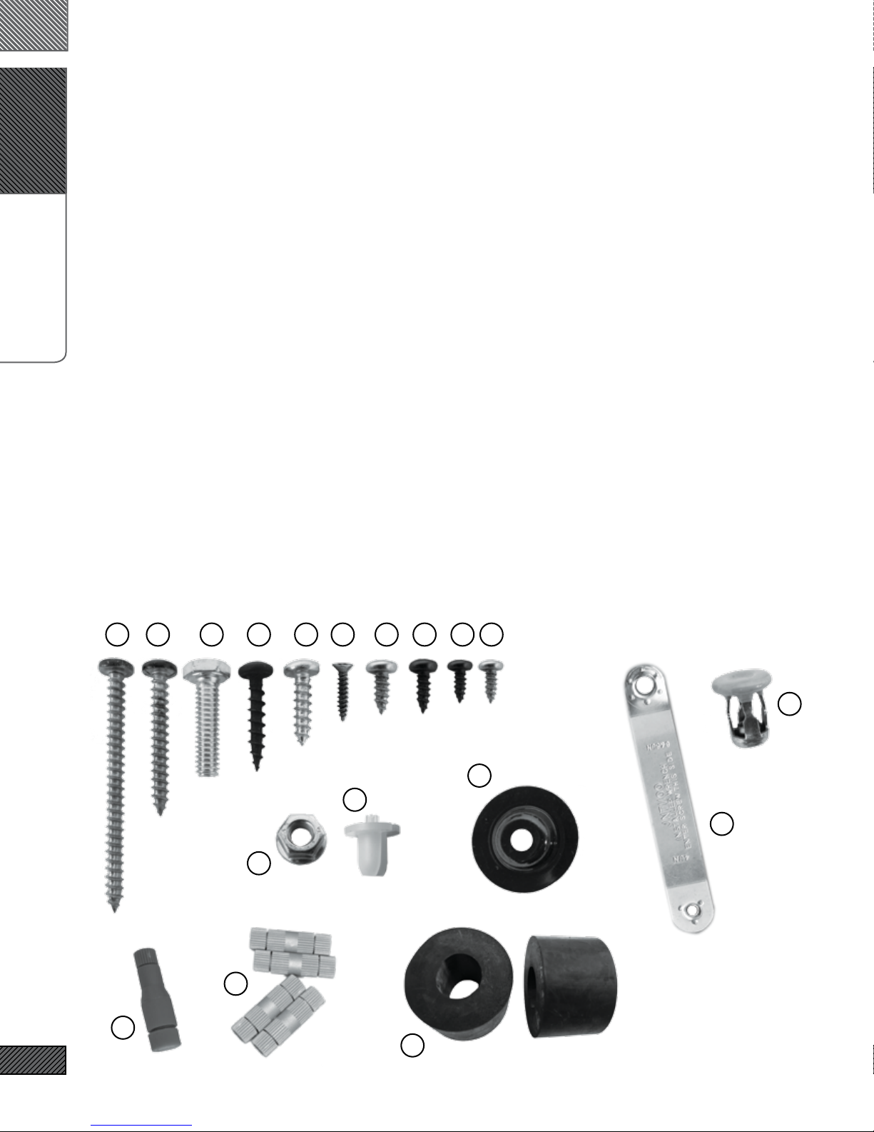
26
SeSelect Hardware for Identification:
2725 29
20
15
231211223028
31
33
21
32
16
5
34

I. PLASTIC PANEL REMOVAL TOOLS
II. TORX BITS:
1. T25
2. T30
3. T40
4. T50
III. DRILL
IV. DRILL BIT:
TOOLS YOU WILL NEED
5. 7/16” [MUST be correct size!]
V. WRENCHES OR SOCKETS:
6. 7/16”
7. 8mm
8. 10mm
9. 10mm Deep [optional}
10. 19mm
VI. ELECTRICIAN’S WIRE FISH
VII. SCISSORS
VIII. UTILITY KNIFE
IX. PLIERS
X. CENTER PUNCH [SUB ONLY]
XI. WIRE STRIPPER [HIFI/HK ONLY]
XII. PICK & HOOK SET [OPTIONAL]
XIII. MAGNETIC PARTS TRAY [OPTIONAL]
6
Images Not to Scale
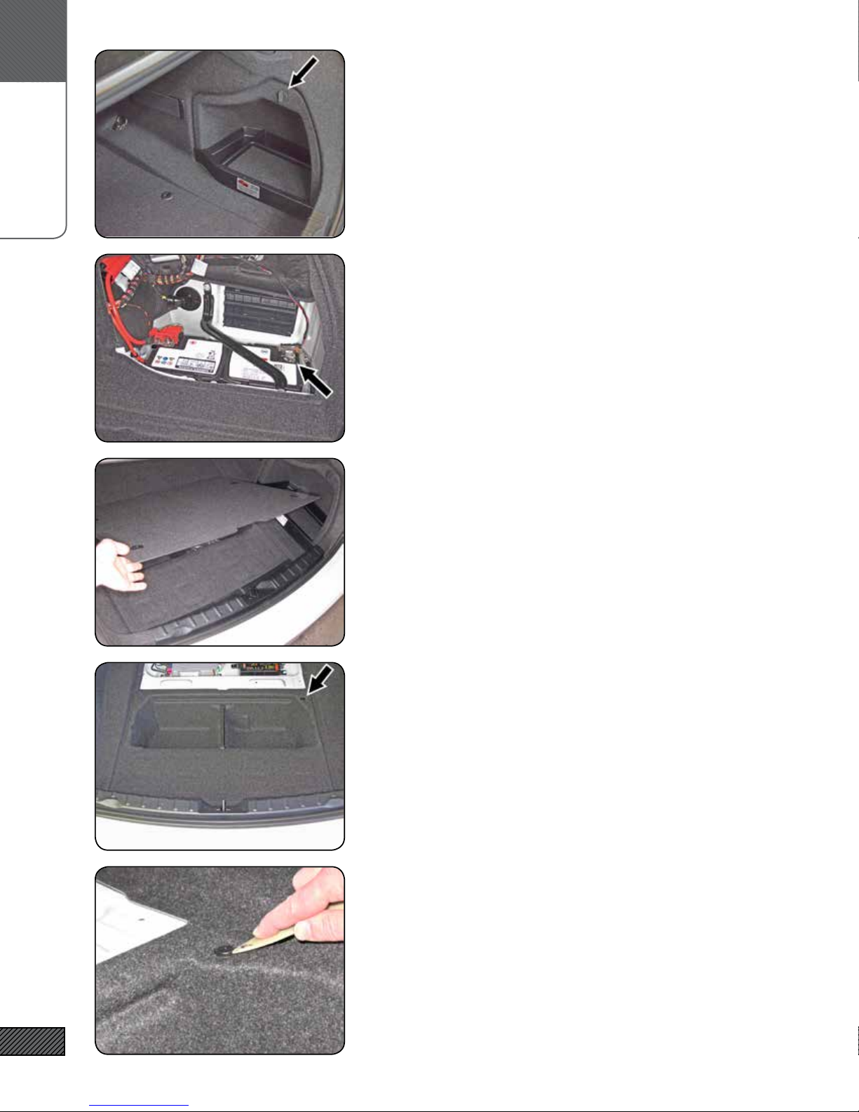
A.
PREP VEHICLE
1. REMOVE BATTERY COVER
Remove battery cover by turning the locking knob and lifting out
the cover.
2. DISCONNECT BATTERY NEGATIVE TERMINAL
Disconnect battery negative terminal with 10mm deep socket.
3. REMOVE TRUNK FLOOR PANEL
Remove the trunk oor panel.
4. REMOVE TRUNK CENTER BIN (STEP 1)
Locate the center pin of the expansion clip at the forward passenger side corner of the liner.
7
5. REMOVE TRUNK CENTER BIN (STEP 2)
With a plastic panel removal tool, pry out center pin of the expansion clip. Pry out clip base. Remove bin liner.
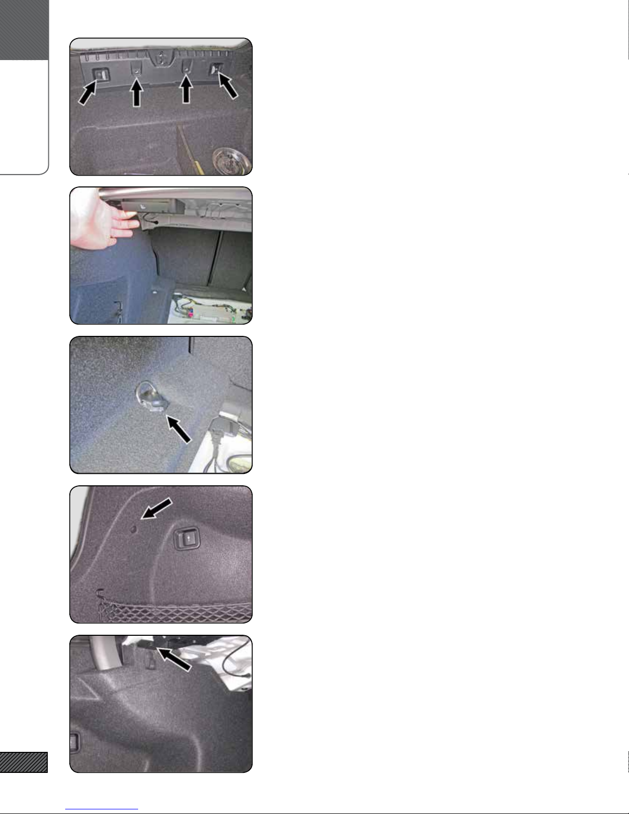
A.
PREP VEHICLE
6. REMOVE TRUNK REAR SILL
Remove the trunk rear sill by removing the (4) center pin expansion clips along the inner side. Lift the lower front edge of the sill
forward to clear the D-rings, then give a rm lift up to release the
friction clips holding the upper portion.
7. FOLD DOWN DRIVER SIDE REAR SEAT
Pull the rear seat release located in the trunk, fold down the driver-side rear seat.
8. REMOVE DRIVER-SIDE REAR QUARTER PANEL TRIM (STEP 1)
Locate the luggage D-ring tie down at the forward driver-side of
the trunk. Pry off the black plastic cover. Remove the Torx T-40
screw. Lift out the D-ring assembly.
9. REMOVE DRIVER-SIDE REAR QUARTER PANEL TRIM (STEP 2)
There are (3) center-pin expansion clips that fasten the rear quarter panel trim to the car - locate & remove the one in the upper
part of the rear cubby area.
8
10. REMOVE DRIVER-SIDE REAR QUARTER PANEL TRIM (STEP 3)
Then locate & remove the one on the side, under the parcel shelf
area. This one is attached to a plastic bracket. Remove the expansion clip on the upper portion of the bracket, and leave the
bracket attached to the quarter-panel trim.
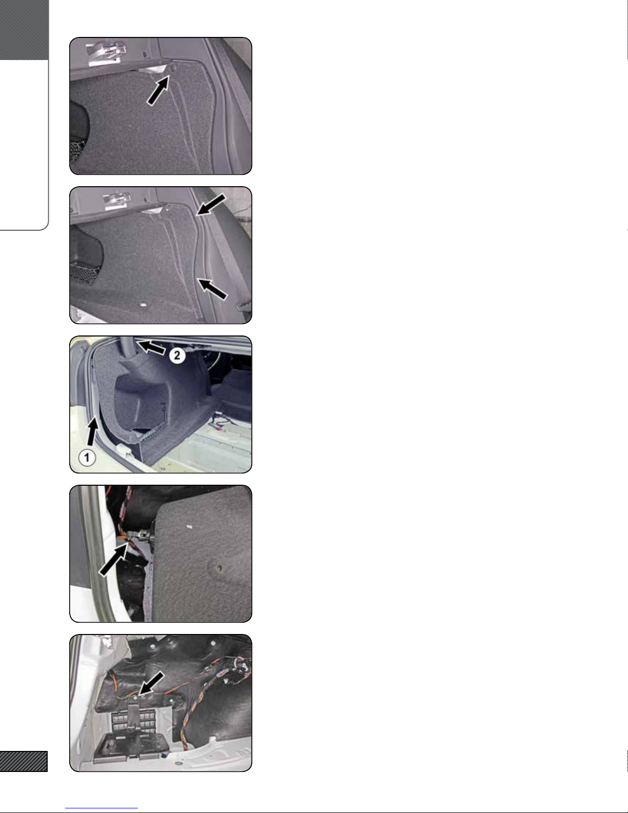
B.
POWER & GROUND WIRING
11. REMOVE DRIVER-SIDE REAR QUARTER PANEL TRIM (STEP 4)
Then locate & remove the one on the forward edge of the panel,
by the rear seat back.
12. REMOVE DRIVER-SIDE REAR QUARTER PANEL TRIM (STEP 5)
Now remove the trim panel. Start at the forward edge. Lift clear/
free the forward edge from behind the trim at the sides of the
rear seat backs and pull the panel out 4-6 inches.
DO NOT COMPLETELY REMOVE YET!
13. REMOVE DRIVER-SIDE REAR QUARTER PANEL TRIM (STEP 6)
Free panel edge along area (1). Then carefully open the split in
the panel at area (2) by pulling the split directly apart (i.e. not
sideways) and free the panel from around the trunk support arm.
DO NOT COMPLETELY REMOVE YET!
14. REMOVE DRIVER-SIDE REAR QUARTER PANEL TRIM (STEP 7)
Disconnect the plug on the back of the 12V power outlet, then
remove the panel from the vehicle.
9
15. REMOVE PLASTIC COVER
Remove the nut fastening the plastic cover over the amp with a
10mm socket. Remove the cover.
 Loading...