

Integral Audio IASS-T, MCSS630MW, MCSS630T, IASS-4, IASS-6 Installation Manual

INSTALLATION GUIDE
SOUNDSTAGE + SUBWOOFER SYSTEM
MINI COOPER CLUBMAN (R55) ver. 5/2017
SKILL LEVEL REQUIRED APPLIES TO
DO-IT-YOURSELF
INSTALLATION DIFFICULTY
3 OUT OF 5
INSTALLATION TIME
6-8 HOURS
OVERVIEW ........................................................................................................................................ 2
BEFORE YOU BEGIN .......................................................................................................................... 2
WHAT’S IN THE BOX - SOUNDSTAGE .................................................................................................. 3
WHAT’S IN THE BOX - SUBWOOFER ................................................................................................... 4
TOOLS YOU WILL NEED ...................................................................................................................... 5
INSTALLATION:
A. Prep Vehicle ........................................................................................................................ 6
B. Power & Ground Wiring ........................................................................................................7
C. Signal Wiring .......................................................................................................................8
D. Amplifier Installation & Speaker wiring...............................................................................9
E. Soundstage speaker installation ....................................................................................... 11
F. Install the Subwoofer [sub only] ........................................................................................ 14
G. Testing & Recommended Initial Settings .......................................................................... 16
TIPS & TUNING ................................................................................................................................ 18
TROUBLESHOOTING ......................................................................................................................... 18
2007+ R55 STANDARD 6 SPEAKER
2007+ R55 HIFI/HK

IMPORTANT
• Read this Guide completely BEFORE you begin.
BEFORE YOU BEGIN
• Disconnect the battery negative terminal while working on the vehicle.
• DO NOT PLACE THE KEY FOB in the vehicle with the battery connected and
the seat airbag wiring disconnected. Doing so will set off the airbag light,
and must be reset by your dealer.
• ALWAYS check behind panels and components before drilling, cutting,
or screwing into any part of a vehicle.
• This guide covers several different vehicle models and options. Some
steps only apply to certain installations. Steps images are labeled with
a black bar across the top:
- [6SPK ONLY]
- [HIFI/HK ONLY] apply only to vehicles equipped with the upgraded 10 speaker HIFI and
- [SUB ONLY] apply only if you are installing the Integral Audio Subwoofer System
- If there is no label, the step applies to ALL installations
- Because each kit applies to more than one vehicle, your kit may include extra items.
apply only to vehicles equipped with the standard 6 speaker audio system.
Harmon Kardon audio system. If the vehicle has tweeters in the A-pillar (near the bottom
outer corners of the windshield), you have the HIFI or HK systems.
2

I. SOUNDSTAGE SPEAKER PACKAGE
1. IASS-T 1” Silk Dome Tweeter (Pair)
2. IASS-4 4” Midrange (Pair)
SOUNDSTAGE
3. IASS-6 6” Midwoofer (Pair)
II. SOUNDSTAGE CROSSOVER NETWORKS WITH VEHICLE-SPECIFIC
TUNING & EQUALIZATION
4. MCSS630MW Mid-Woofer Network (Pair)
5. MCSS630T Tweeter Network (Pair)
III. ARC AUDIO KS MINI AMPLIFIER (2CH W/SOUNDSTAGE, 4CH W/
SOUNDSTAGE + SUBWOOFER)
IV. SIGNAL & SPEAKER WIRING HARNESSES
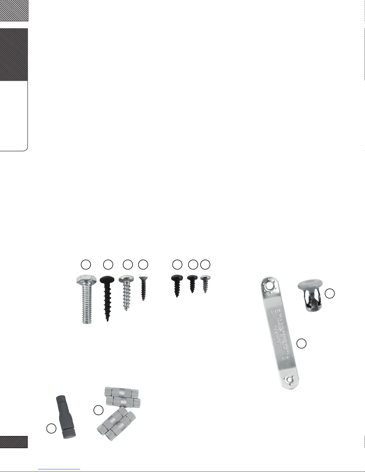
WHAT’S IN THE BOX
6. Signal Wiring Harness (MCWH-SIG-R)
7. Mid-Woofer Connection Harness (Pair)
8. Tweeter Pigtail (Pair)
V. SOUNDSTAGE HARDWARE
9. Midrange Mounting Adapter (Pair)
10. Midwoofer Mounting Adapter (Pair)
11. #8 x 1/2” Midwoofer Mounting Screws (12)
12. #6 x 3/8” Midrange Mounting Screws (12)
13. Integral Audio Logo Badge (Pair)
VI. AMPLIFIER INSTALLATION & WIRING
14. Amplfier Power Wiring Harness (complete)
15. Threadlock Wire Splice Connectors (4) [HIFI/HK ONLY]
16. Threadlock Wire Tap (1)
17. Cable Ties (10)
18. 3M Electrical Tape
VII. AMPLIFIER MOUNTING (UNDERSEAT AMP MOUNT)
19. Amplifier Mounting Bracket
20. #6 x 3/8” Pan Head Screw (4)
VIII. MULTIFUNCTION BOX COVER (UNDERSEAT COVER) [OPTIONAL}
IX. FACTORY A-PILLAR TRIM W/TWEETER MOUNTS [OPTIONAL]
3
Continued on the next page . . .
X. MC800S SUBWOOFER ENCLOSURE
XI. INTEGRAL AUDIO ALCHEMY 10” SUBWOOFER
XII. SPARE TIRE WELL COVER PANEL
XIII. SUBWOOFER HARDWARE
SUBWOOFER
WHAT’S IN THE BOX
21. Neutrik Speak-On Terminal & Gasket
22. ¼” x 1” Hex Head Bolt
23. #10 x 1” Black Pan Head Screw (8)
24. #10 x ¾” Pan Head Screw (8)
25. #4 x ½” Black Flathead Screw (2)
26. Threaded Insert (3)
27. Threaded Insert Installation Wrench
28. Subwoofer Mounting Bracket (2)
29. Rosette Thumbscrew (2)
30. Connection Harness (Sub to Neutrik)
XIV. REMOTE LEVEL CONTROL
31. Integral Audio Remote Level Control
32. 3M VHB Double-Sided Mounting Tape (3in)
SeSelect Hardware for Identification:
22 24
15
2012112523
26
27
16
4

I. PLASTIC PANEL REMOVAL TOOLS
II. TORX BITS:
1. T25
2. T30
3. T40
4. T50
III. DRILL
IV. DRILL BIT:
TOOLS YOU WILL NEED
5. 7/16” [MUST be correct size!]
V. WRENCHES OR SOCKETS:
6. 7/16”
7. 8mm
8. 10mm
9. 10mm Deep [optional}
10. 19mm
VI. ELECTRICIAN’S WIRE FISH
VII. SCISSORS
VIII. UTILITY KNIFE
IX. PLIERS
X. DIGITAL MULTIMETER
XI. TEST TONE CD (availble for download at
www.integralaudio.com/other_files/test_cd/)
XII. CENTER PUNCH [SUB ONLY]
XIII. STIFF PUTTY KNIFE OR 5-IN-1 [SUB ONLY]
XIV. WIRE STRIPPER [HIFI/HK ONLY]
XV. PICK & HOOK SET [OPTIONAL]
XVI. MAGNETIC PARTS TRAY [OPTIONAL]
5
IMAGES NOT TO SCALE
A.
PREP VEHICLE
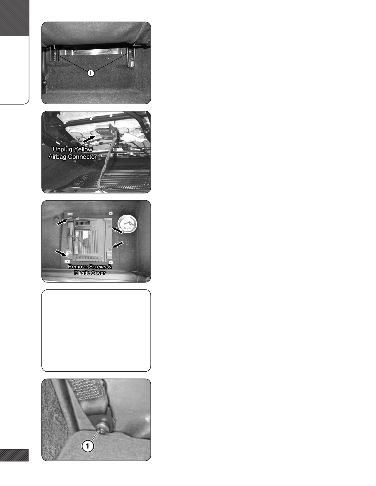
1. REMOVE PASSENGER SEAT
Slide the seat forward. Using a Torx T-40, remove the two screws
holding the rear of the seat (1). Slide the seat backward and repeat for the two front screws.
2. REMOVE PASSENGER SEAT (PART 2)
Tilt the seat back. Disconnect the airbag wiring under the seat by
pulling the black slide catch on the side of the yellow plug. Disconnect the seat heater wiring if equipped. DO NOT put the key
FOB in the ignition while this plug is disconnected. Remove the
seat from the vehicle.
SEE PREVIOUS
IMAGES
3. REMOVE PASSENGER SEAT (PART 3)
If present, remove the plastic panel under the seat.
4. REMOVE DRIVER SEAT
Repeat the previous steps to remove the Driver seat.
[This step is not absolutely necessary, but it does make later steps
easier and is recommended.]
6
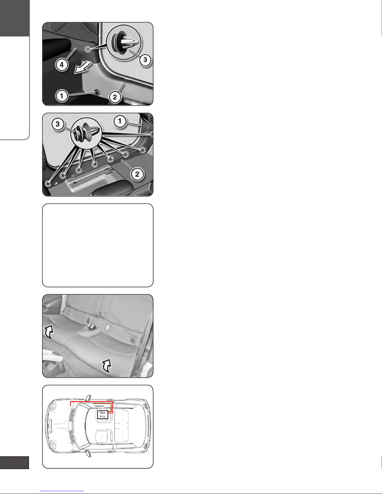
5. REMOVE LEFT DOOR SILL TRIM (PART 1)
Using a Torx T-50 bit, remove the seat belt screw (1) where it
passes through the rear of the door sill trim.
B.
POWER & GROUND WIRING
6. REMOVE LEFT DOOR SILL TRIM (PART 2)
Remove metal seat belt bushing (1) if not removed in the previous
step. Pull Rear Side Trim Panel (4) in, releasing clip (3) and freeing
tab of Door Sill (2) located behind Side Panel (4).
7. REMOVE LEFT DOOR SILL TRIM (PART 3)
[Seat shown removed for clarity]
Remove the door seal over the entire length of the right door sill
by lifting it up and off. Pull up/loosen the rubber door seal gasket along the length of the door. Pull Door Sill Panel (2) inward,
releasing clips (3). This requires a rm pull at each of the clip
locations. Remove the small trim piece (1) by pulling it toward
the rear of the vehicle, releasing spring clip.
SEE PREVIOUS
IMAGES
8. REMOVE THE RIGHT DOOR SILL TRIM
Repeat the previous three steps for the Right Side of the vehicle.
9. RELEASE FRONT OF THE REAR SEAT BOTTOM
Pull up rmly on the front of the edge of the rear seat bottom to
release. This will allow you access underneath the carpet in later
steps.
7
10. POWER & GROUND WIRING (OVERVIEW)
The 12V+ wire runs directly from the battery to the new amplier
that installs under the passenger seat. An inline fuse is installed
at the battery.
The Ground wire runs from the amplier to one of the factoryinstalled common ground points along the door sill
B.
POWER & GROUND WIRING
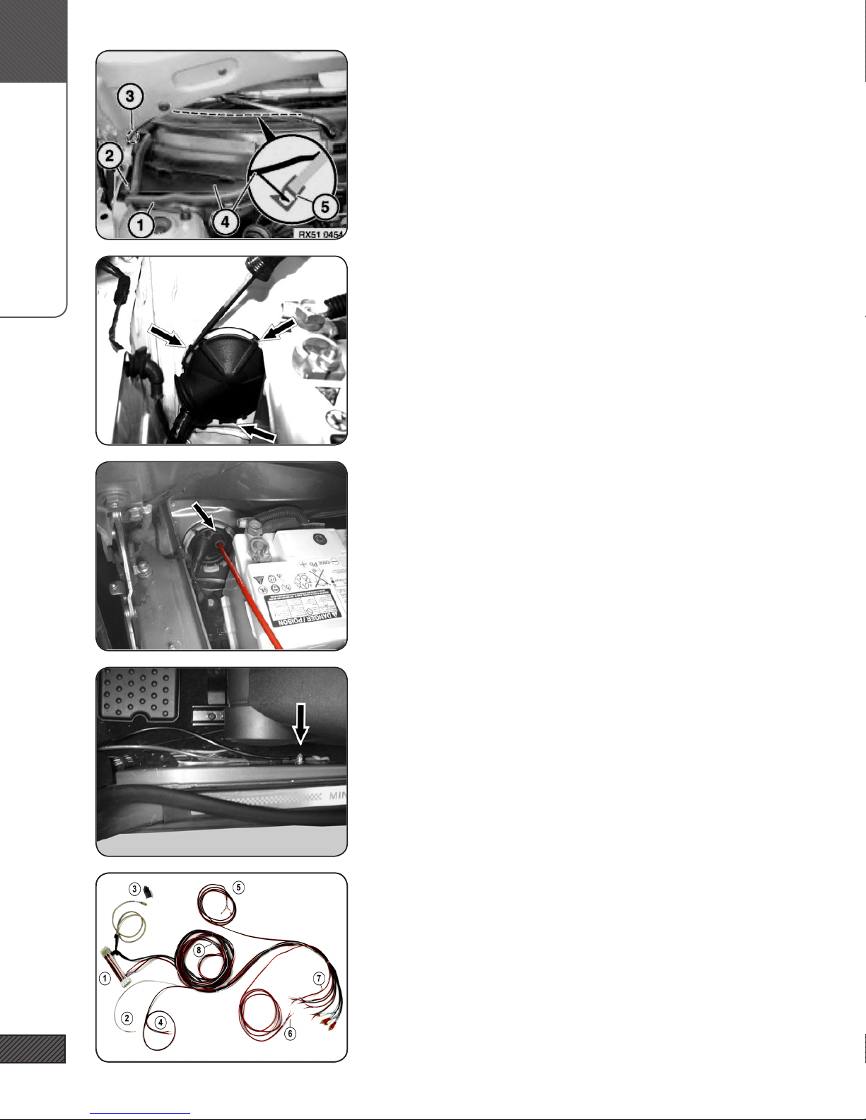
11. REMOVE RIGHT COWL PANEL
Open the Bonnet (aka the hood!). Remove the black plastic Cowl
covering the battery by releasing nuts (2) and (3) with a 10mm
socket. Loosen & remove cowl.
NOTE: When replacing the cowl, be sure the seal (1) is seated
properly and that the secondary tab of the cowl (4) is inserted into
the plastic channel (5) that attaches to the bottom of the windshield.
12. REMOVE THRU-WALL COVER
Remove the battery.
Locate the thru-wall bushing behind the battery. Using a at
screwdriver, release the indicated retaining tabs then remove the
plastic thru-wall cover to expose the thru-wall opening.
13. POWER WIRE
Locate the Power Wire (with fuse holder) in the amp wiring kit.
REMOVE THE FUSE IF INSTALLED IN THE HOLDER! Feed the Red
Power Wire through the spare wiring nipple and into the cabin.
From inside the vehicle, locate the wire coming in. Feed the wire
around the fuse box and along the Right Door Sill.
Remove the auxiliary nut on the battery post with a 19mm socket
and attach the ring terminal on the end of the power wire.
14. GROUND WIRE
Locate the Common Ground point under the Right Door Sill. Remove the nut with a 10mm socket. Attach the ring terminal of
the Black Ground Wire to the Common Ground point.
NOTE: On some vehicles the common ground is located a bit
further forward. Enough ground wire is included to reach either
location.
8
15. SIGNAL WIRING HARNESS (OVERVIEW)
The signal wiring harness contains all wiring for low and high
level signals, remote volume, and remote turn on. Items are:
(1) X9331 T-harness; (2) Remote turn-on wire; (3) Subwoofer
remote volume control; (4) Left Tweeter speaker wire; (5) Right
Tweeter speaker wire; (6) Subwoofer speaker wire; (7) RCA &
Speaker wire connections to ARC Amplier; (8) Inline labels for
HIFI/HK systems
 Loading...