

INTEGRAL IN91260CN Datasheet

TECHNICAL DATA
1
10 Memory Tone/Pulse Dialer
High-Performance Silicon-Gate CMOS
The IN91260C is tone/pulse switchable dialer with ten 16-digit
number memories and 32-digit redial memory. Pulse to tone mode
switching is performed via a slide switch.
•
32-digit redial memory (31 digits in tone mode)
•
Ten indirect memories, 16 digits in pulse mode, 15 digits in tone
mode
•
Tone/Pulse mode switching via slide switch (4.1 second pause
inserted automatically)
•
Wide operating voltage: 1.8 V ∼ 5.5 V
•
Uses 480 KHz ceramic resonator
•
Low memory retention current
•
Selectable Make/Break ratio
•
Dial Pulse Rate: 10 pps
Keyboard Assignments*
123 S R1
456 A/L R2
789 P R3
*0# R R4
C1 C2 C3 C4
IN91260C
ORDERING INFORMATION
IN91260CN
TA = -20° to 70° C
PIN ASSIGNMENT
LOGIC DIAGRAM
PIN 11 = GND
PIN 10 = V
CC
S: Store
A/L : Auto/Location
P: Pause
R: Redial
IN91260C
2
Pin Description
Pin No. Designation Description
1R1
2R2
3R3
4R4
5 HK Hook switch input.
When HK = V
CC
, an ON-Hook state exists.
When HK = GND, an Off-Hook state exists.
6 M/B Dial pulse Make/Break ratio select input.
If M/B = V
CC
, the Make/Break ratio is 1/2.
If M/B = GND, the Make/Break ratio is 2/3.
7 MODE SELECT Pulse/DTMF mode select input.
If MODE SELECT = V
CC
, Pulse mode is in effect.
If MODE SELECT = GND, DTMF mode is in effect.
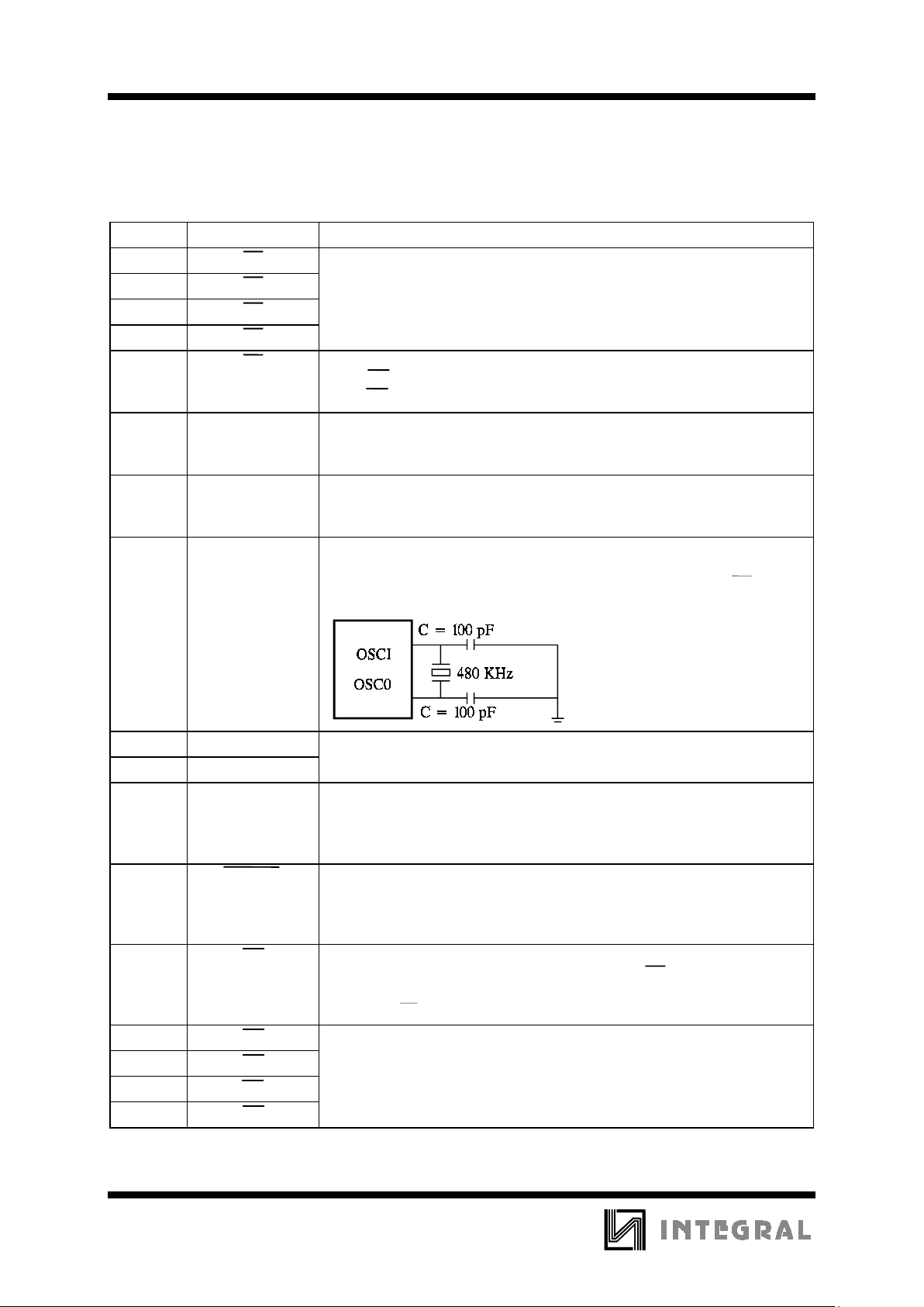
8
9
OSCI
OSC0
Oscillator I/O.
A 480 KHz ceramic resonator and two 100 pF serial loading capacitors form
a complete oscillator circuit. The circuit is activated when HK is low.
Oscillator start-up time is typically 10 ms.
10 V
CC
11 GND
12 TONE DTMF signal output.
Pull-down load resistance is 10,000 Ω.
The minimum tone and IDP durations are built-in for both normal dialing
and redialing.
13 XMUTE Transmit mute output.
This is an N-channel open drain output. The output transistor is switched on
while a sequence of digits is being dialed (for both Pulse and Tone modes).
Otherwise, it is switched off.
14 DP Dial pulse output.
This pin is an N-channel open drain output. When DP output is low
(switched on), it serves as a break signal in Pulse dialing. For other
operations, DP output is normally high impedance (switched off).
15 C1
16 C2
17 C3
18 C4
Keyinputs.
When a row and a column are connected, a key operation is activated.
Scanning signals are present on both the row and column pins during a
valid key-in condition.
Keyinputs.
When a row and a column are connected, a key operation is activated.
Scanning signals are present on both the row and column pins during a valid
key-in condition.
Positive power supply.
Negative power supply.
IN91260C
3
Operation Procedures
Symbol Definitions:
a. D
P
: Pulse digit, 1, 2, 3, 4, 5, 6, 7, 8, 9, 0
b. D
t
: tone digit, 1, 2, 3, 4, 5, 6, 7, 8, 9, 0, *, #
c. LOCi : i = 1, 2, 3, 4, 5, 6, 7, 8, 9, 0
d. ZiZiZi : Conversation mode
e. 0 - 0 ↑ : OFF-HOOK
f. 0 - 0 ↓ : ON-HOOK
g. : Input Level from Low to High
h. : Input Level from High to Low
Recommended dialing, redialing, mixed dialing
and storing operations:
1. Normal dialing in pulse mode
0 - 0 ↑ , D
P
. . . DP, ZiZiZi 0 - 0
↓
2. Normal dialing in tone mode
0 - 0 ↑ , D
t
. . . Dt, ZiZiZi 0 - 0
↓
3. Mixed dialing in pulse-to-tone mode
0 - 0 ↑ , D
P
. . . DP, MODE SELECT
, D
t
. . . Dt, ZiZiZi 0 - 0
↓
4. Redialing
0 - 0 ↑ , D
P
. . . D
P
0 - 0 ↓, 0 - 0 ↑, R, ZiZiZi, 0
- 0
↓
0 - 0 ↑ , D
t
. . . Dt 0 - 0 ↓, 0 - 0 ↑, R, ZiZiZi, 0
- 0
↓
5. Storing Numbers to Repertory Memory
(i) Off-hook Store 0 - 0 ↑, S , D
P
. . . D
P
or Dt . . . Dt , A/L , LOCi, 0 - 0
↓
(ii) On/Off-hook store: 0 - 0 ↓, S , D
P
. . . D
P
or
D
t
. . . Dt , A/L , LOCi
6. Dialing from Repertory Memory
0 - 0 ↑, A/L , LOCi, ZiZiZi 0 - 0
↓
Functional Description
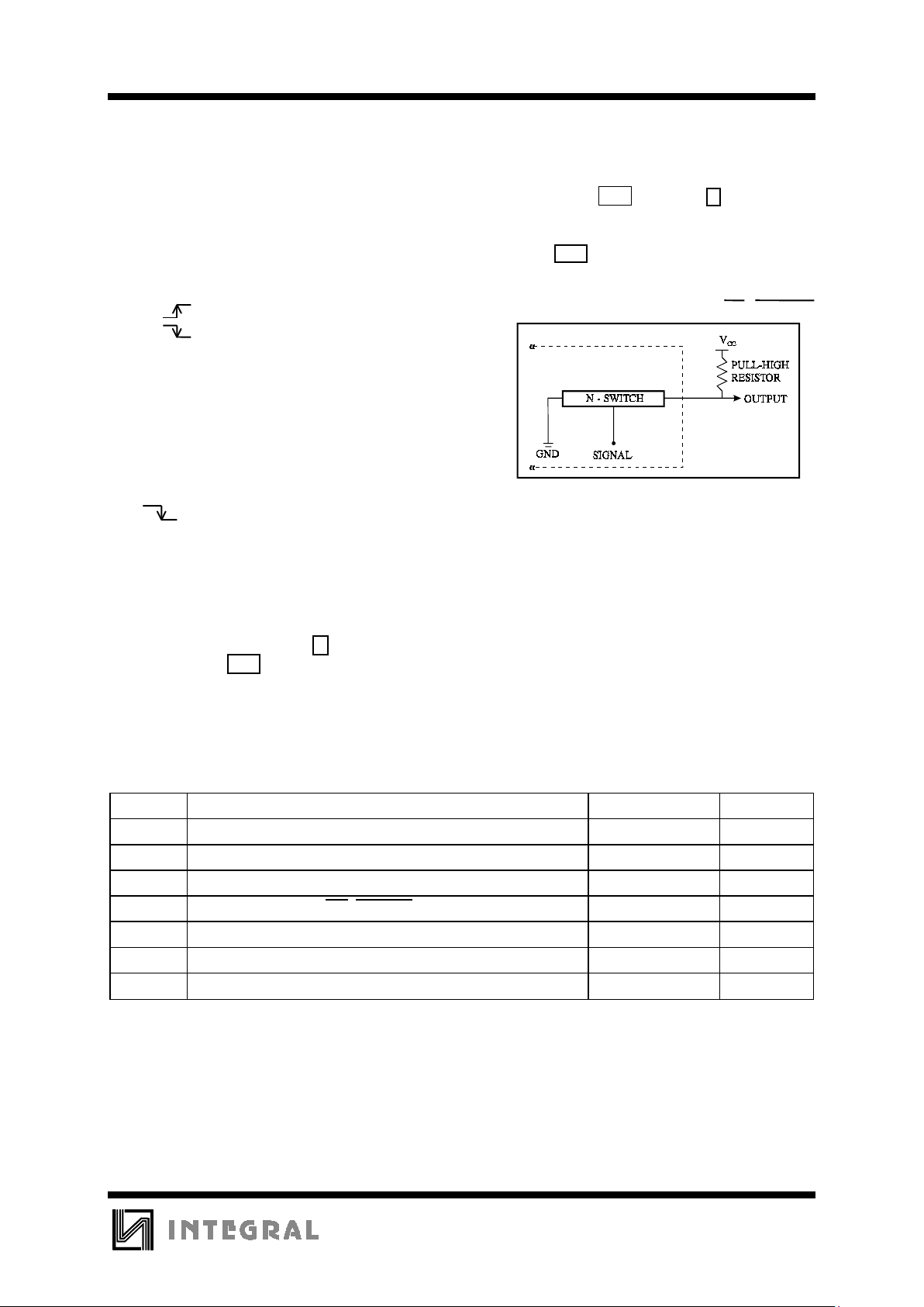
1. N-Channel Open Drain Output - DP, XMUTE
F
igure 1.
2. DTMF Generator
The digitally synthesized sinewave of the
IN91260 series is well designed, with a 6 level,
12 segment, 1/2 V
CC
reference voltage. The THD
(Total Harmonic Distortion) of the DTMF output
is typically 1%, when V
CC
= 2.5 V to 5.5 V and
frequency is in the 500 HZ to 3400 HZ band.
MAXIMUM RATINGS
*
Symbol Parameter Value Unit
V
CC
DC Supply Voltage (Referenced to GND) -0.3 to +6.0 V
V
IN
DC Input Voltage (Referenced to GND) -0.3 to VCC +0.3 V
V
OUT
DC Output Voltage (Referenced to GND) -0.3 to VCC +0.3 V
V
OUT
DC Output Voltage (DP, XMUTE) -0.3 to 1.2 V
I
TONE
DC Output Current(Tone) 50 mA
P
D
Power Dissipation in Still Air, Plastic DIP
**
500 mW
Tstg Storage Temperature -40 to +125
°
C
*
Maximum Ratings are those values beyond which damage to the device may occur.
Functional operation should be restricted to the Recommended Operating Conditions.
**
Durating: -10 mW/
°
C
from 65°C to 70°C.
 Loading...