

INTEGRAL ILA7052 Datasheet
ILA7052
ILA7052
MONO OUTPUT AMPLIFIER
GENERAL DESCRIPTION
The ILA7052 is a mono output amplifier in a 8-lead dual-in-line (DIL) plastic package. The device is designed
for battery-fed portable audio applications.
Features:
• No external components
• No switch-on or switch-off clicks
• Good overall stability
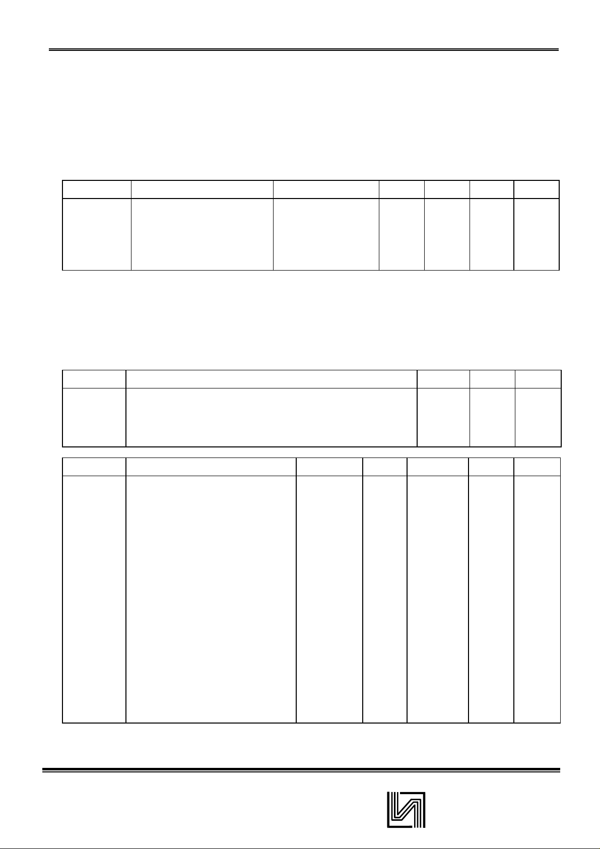
QUICK REFERENCE DATA
SYMBOL PARAMETER CONDITIONS MIN. TYP. MAX. UNIT
Vp Supply voltage range 3 6 18 V
ltot Total quiescent current
Gv Voltage gain 38 39 40 dB
Po Output power
THD Total harmonic distortion Po=0,1W - 0,2 1,0 %
L
=∞~
R
THD = 10%; 8 Q
PACKAGE OUTLINE 8-lead DIL; plastic (SOT97); SOT97-1;
PINNNG
1 Vp suppl y vol tage 5 OUT1 output 1
2 IN input 6 GND2 ground (substrate)
3 GND1 ground (signal) 7 n.c. not connected
4 n.c. not connected 8 OUT2 output 2
• Low power consumption
• No external heatsink required
• Short-circuit proof
-48mA
-1,2-W
RATINGS
SYMBOL PARAMETER MIN. MAX. UNIT
Vp Supply voltage - 18 V
OSM
I
Tc Crystal temperature - 150 °C
Tstg Storage temperature range -55 +150 ' °C
CHARACTERISTICS Vp = 6 V;
SYMBOL PARAMETER CONDITIONS MIN. TYP. MAX. UNIT
Supply
Vp Supply voltage range 3 6 18 V
ltot Total quiscent current
Gv Voltage gain 38 39 40 dB
Po Output power THD = 10% - 1,2 - W
Vno(rms) note 1 - 150 300 mV
Vno(rms) note 2 - 60 - mV
fr Frequency response - 20 Hz to - Hz
SVRR Supply voltage ripple rejection note 3 40 50 - dB
V
∆
5-8
THD Total harmonic distortion PO=0.1W - 0,2 1 ,0 %
IZiI Input impedance - 100 -
Ibias Input bias current - 100 300 nA
Limiting values in accordance with the Absolute Maximum System (IEC 134)
Non-repetitive peak output current - 1,5 A
RL
= 8 Q; f = 1 kHz; Tamb = 25 °C; unless otherwise specified.
-4 8mA
20 kHz
-- 100mV
Noise output voltage
(RMS value)
DC output offset voltage
pin 5 to 8
L
=
R
∞
Rs = 5 k
Ω
k
Ω
1
INTEGRAL

ILA7052
Notes to the characteristics
1. The unweighted RMS noise output voltage is measured at a bandwidth of 60 Hz to 15 kHz with a source impedance (Rs) of 5
kΩ.
2. The RMS noise output voltage is measured at a bandwidth of 5 kHz with asource impedance of 0 Ω and a frequency of 500
kHz. With a practical load (R= 8 Ω; L = 200µH) the noise output current is only 100 nA.
3. Ripple rejection is measured at the output with a source impedance of 0 Q and a frequency between 100 Hz and 10 kHz.
The ripple voltage = 200 mV (RMS value) is applied to the positive supply rail.
2
INTEGRAL
 Loading...