

INTEGRAL ILA1062AN Datasheet
TECHNICAL DATA
1
Low Voltage Transmission Circuit
with Dialler Interface
The ILA1062A is an integrated circuit that perform all speech and line
interface functions required in fully electronic telephone sets. They
perform electronic switching between dialling and speech. The ICs
operate at line voltage down to 1.6 V DC (with reduced performance)
to facilitate the use of more telephone sets connected in parallel.
•
Low DC line voltage: operates down to 1.6 V (excluding polarity
guard)
•
Voltage regulator with adjustable static resistance
•
Provides a supply for external circuits
•
Symmertical high-impedance inputs (64 KΩ) for dynamic,
magnetic or piezo-electric microphones
•
Asymmetrical high-impedance input (32 KΩ) for electret
microphones
•
DTMF signal input with confidence tone
•
Mute input for pulse or DTMF dialing:
active LOW (MUTE)
•
Receiving amplifier for dynamic, magnetic or piezo-electric
earpieces
•
Large gain setting ranges on microphone and earpiece amplifiers
•
Line loss compensation (line current dependent) for microphone
and earpiece amplifiers
•
Gain control curve adaptable to exchange supply
•
DC line voltage adjustment facility
ILA1062A
ORDERING INFORMATION
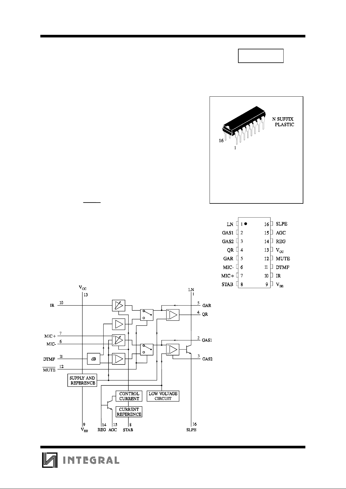
ILA1062AN Plastic
TA = -25° to 75° C
for package
PIN ASSIGNMENT
BLOCK DIAGRAM
ILA1062A
2
PIN DESCRIPTION
Pin No Designation Description
1 LN positive line terminal
2 GAS1 gain adjustment; transmitting amplifier
3 GAS2 gain adjustment; transmitting amplifier
4 QR non-inverting output; receiving amplifier
5 GAR gain adjustment; receiving amplifier
6 MIC- inverting microphone input
7 MIC+ non-inverting microphone input
8 STAB current stabilizer
9VEEnegative line terminal
10 IR receiving amplifier input
11 DTMF dual-tone multi-frequency input
12 MUTE mute input
13 V
CC
possitive supply decoupling
14 REG voltage regulator decoupling
15 AGC automatic gain control input
16 SLPE slope (DC resistance) adjustment
FUNCTIONAL DESCRIPTION
Supplies VCC, LN, SLPE, REG and STAB
Power for the IC and its peripheral circuits is usually
obtained from the telephone line. The supply voltage
is derived from the line via a dropping resistor and
regulated by the IC. The supply voltage V
CC
may
also be used to supply external circuits e.g. dialling
and control circuits.
Decoupling of the supply voltage is performed by a
capacitor between V
CC
and VEE. The internal voltage
regulator is decoupled by a capacitor between REG
and V
EE
.
The DC current flowing into the set is determined by
the exchange supply voltage V
exch
, the feeding bridge
resistance R
exch
and the DC resistance of the
telephone line R
line
.
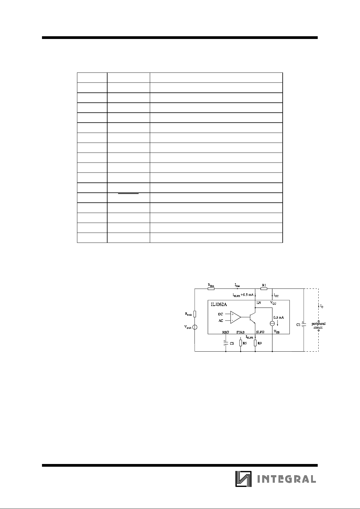
The circuit has an internal current stabilizer
operating at a level determined by a 3.6 KΩ resistor
connected between STAB and V
EE
(see Fig.1).
Figure 1. Supply arrengement
When the line current (I
line
) is more than 0.5 mA
greater than the sum of the IC supply current (I
CC
)
and the current draw by the peripheral circuitry
connected to V
CC
(Ip) the excess curre nt is shunt ed to
V
EE
via LN.
The regulated voltage on the line terminal (V
LN
) can
be calculated as:
V
LN
= V
ref
+ I
SLPE
x R9
V
LN
= V
ref
+ ((I
line
- ICC - 0.5 x 10⁻³ A)-Ip) x R9
ILA1062A
3
V
ref
is an internally generated temperature
compensated reference voltage of 3.7 V and R9 is
an external resistor connected between SLPE and
V
EE
.
In normal use the value of R9 would be 20Ω.
Changing the value of R9 will also affect
microphone gain, DTMF gain, gain control
characteristics, sidetone level, maximum output
swing on LN and the DC characteristics (especially
at the lower voltages).
Under normal conditions, when
I
SLPE
>>ICC + 0.5 mA + Ip, the static behaviour of the
circuit is that of a 3.7 V regulator diode with an
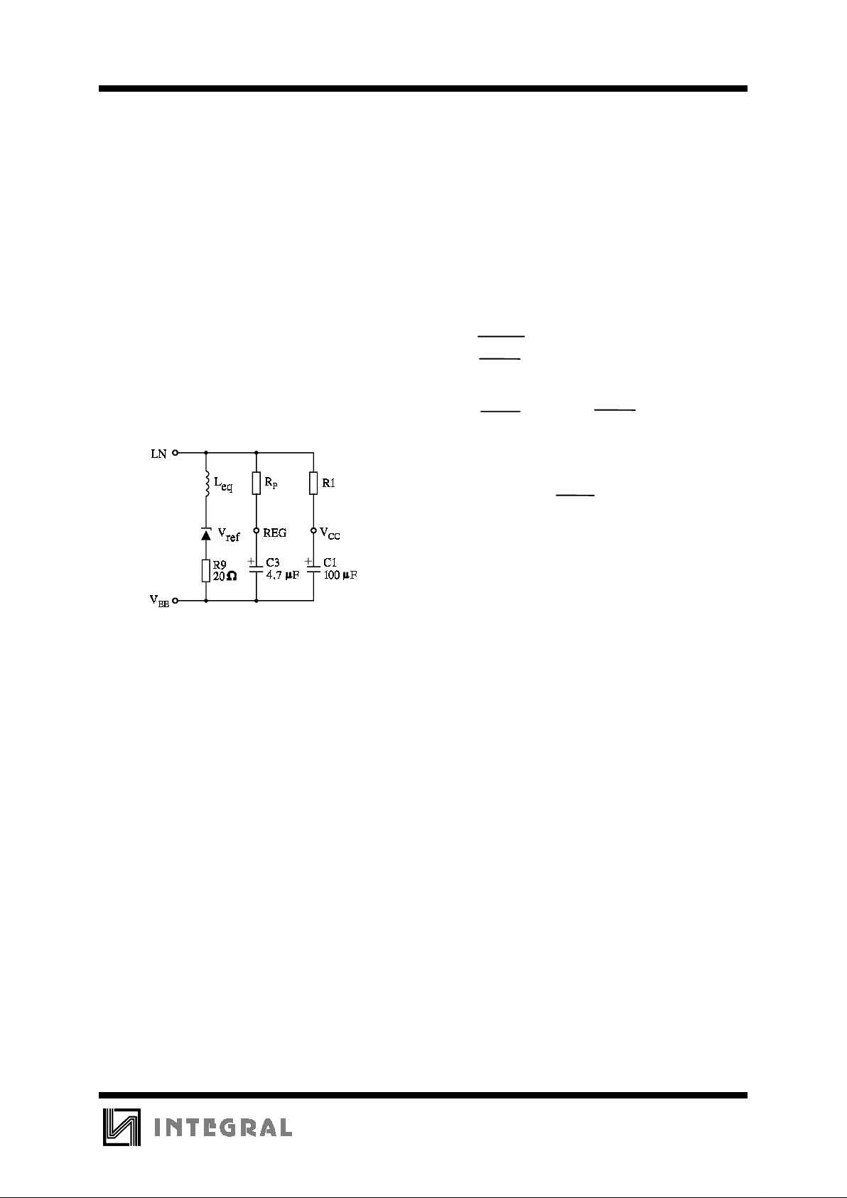
internal resistance equal to that of R9. In the audio
frequency range the dynamic impedance is largely
determined by R1. Fig.2 shows the equivalent
impedance of the circuit.
Leq = C3 x R9 x R
P
RP = 16.2 K
Ω
Figure 2. Equivalent impedance circuit
At line currents below 9 mA the internal reference
voltage is automatically adjusted to a lower value
(typically 1.6 V at 1 mA) This means that more sets
can be operated in parallel with DC line voltages
(excluding the polarity guard) down to an absolute
minimum voltage of 1.6 V.
At line currents below 9 mA the circuit has limited
sending and receiving levels. The internal reference
voltage can be adjusted by means of an external
resistor (R
VA
). This resistor when connected between
LN and REG will decrease the internal reference
voltage and when connected between REG and
SLPE will increase the internal reference voltage.
Microphone inputs MIC+ and MIC- and gain
pins GAS1 and GAS2
The circuit has symmetrical microphone inputs. Its
input impedance is 64 KΩ (2 x 32 KΩ) and its
voltage gain is typically 52 dB (when R7 = 68 KΩ,
see Figure 3). Dynamic, magnetic, piezo-electric or
electret (with built-in FET source followers) can be
used.
The gain of the microphone amplifier can be
adjusted between 44 dB and 52 dB to suit the
sensitivity of the transducer in use. The gain is
proportional to the value of R7 which is connected
between GAS1 and GAS2.
Stability is ensured by two external capacitors, C6
connected between GAS1 and SLPE and C8
connected between GAS1 and V
EE
. The value of C6
is 100 pF but this may be increased to obtain a firstorder low-pass filter. The value of C8 is 10 limes the
value of C6. The cut-off frequency corresponds to
the time constant R7 x C6.
Input MUTE
When MUTE is LOW or open circuit, the DTMF
input is enabled and the microphone and receiving
amplifier inputs are inhibited. The reverse is true
when MUTE is HIGH, MUTE switching causes only
negligible clicking on the line and earpiece output. If
the number of parallel sets in use causes a drop in
line current to below 6 mA the DTMF amplifier
becomes active independent to the DC level applied
to the MUTE input.
Dial-tone multi-frequency input DTMF
When the DTMF input is enabled dialling tones may
be sent on to the line. The voltage gain from DTMF
to LN is typically 25.5 dB (when R7 = 68 KΩ) and
varies with R7 in the same way as the microphone
gain. The signalling tones can be heard in the
earpiece at a low level (confidence tone).
Receiving amplifier IR, QR and GAR
The receiving amplifier has one input (IR) and a
non-inverting output (QR). The IR to QR gain is
typically 31 dB (when R4 = 100 KΩ). It can be
adjusted between 20 and 31 dB to match the
sensitivity of the transducer in use. The gain is set
with the value of R4 which is connected between
GAR and QR. The overall receive gain, between LN
and QR, is calculated by subtracting the antisidetone network attenuation (32 dB) from the
amplifier gain. Two external capacitors, C4 and C7,
ensure stability. C4 is normally 100 pF and C7 is 10
times the value of C4. The value of C4 may be
increased to obtain a first-order low-pass filter. The
cut-off frequency will depend on the time constant
R4 x C4.
The output voltage of the receiving amplifier is
specified for continuous-wave drive. The maximum
output voltage will be higher under speech
conditions where the peak to RMS ratio is higher.
 Loading...