

Page 1
VIAFLO 96/384 Operating instructions
125950_V11
Page 2

Declaration of conformity
INTEGRA Biosciences AG – 7205 Zizers, Switzerland
declares on its own responsibility that the devices
Description Models
VIAFLO 96 6000, 6001
VIAFLO 384 6030, 6031
comply with:
EU Directives (DoW: Date of Withdrawal) Before DoW DoW After DoW
Low Voltage Equipment 2006/95/EC 20.04.2016 2014/35/EU
Electromagnetic Compatibility 2004/108/EC 20.04.2016 2014/30/EU
Restriction of Hazardous Substances 2011/65/EU
Waste Electrical and Electronic Equipment 2012/19/EU
EU Regulations
Registration, Evaluation, Authorisation and Restriction of Chemicals (REACH)
Standards for EU
Safety requirements for electrical equipment for measurement,
EN 61010-1: 2010
control and laboratory use - General requirements.
Particular requirements for automatic and semi-automatic
EN 61010-2-81: 2015
laboratory equipment for analysis and other purposes.
Electrical equipment for measurement, control and laboratory use
EN 61326-1: 2013
- EMC requirements.
1907/2006
Standards for Canada and USA
Safety requirements for electrical equipment for measurement,
control and laboratory use - General requirements
Safety requirements for electrical equipment for measurement,
control and laboratory use - General requirements
Particular requirements for automatic and semi-automatic laboratory
equipment for analysis and other purposes
a
.
a
.
a
.
Operation is subject to the following two conditions: (1) this device may not
cause harmful interference, and (2) this device must accept any interference received, including interference that may cause undesired operation.
a
NRTL certificate number (TÜV Süd): U8 17 05 42035 007
Zizers, June 19, 2017
Elmar Morscher
CEO
Thomas Neher
Quality Manager
CAN/CSA-C22.2
No. 61010-1
UL 61010-1
UL 61010-2-81
Part 15 of the
FCC Rules
Class A
Page 3

VIAFLO 96/384 – Operating instructions V11
Table of Contents
Chapter 1 Introduction
1.1 Symbols used...................................................................................7
1.2 Intended use.....................................................................................7
1.3 Safety notes .....................................................................................8
Chapter 2 Description of the device
2.1 Scope of delivery..............................................................................9
2.2 Overview of VIAFLO 96/384.............................................................9
2.2.1 VIAFLO 96/384 device..........................................................9
2.2.2 VIAFLO 96/384 control unit.................................................10
2.2.3 Display ................................................................................10
2.2.4 Touch wheel........................................................................11
2.2.5 Left and right arrow buttons ................................................11
2.2.6 PURGE button ....................................................................11
2.2.7 RUN key..............................................................................11
Chapter 3 Installation
3.1 Operating environment...................................................................12
3.2 Setting up and moving of the instrument........................................12
3.3 Getting started................................................................................13
3.4 Toolbox - adapt your VIAFLO 96/384.............................................14
3.4.1 Change head ......................................................................14
3.4.2 Storage of pipetting heads..................................................15
3.4.3 Position Settings .................................................................16
3.4.4 Preferences.........................................................................16
3.4.5 Calibration & Services.........................................................18
3.4.6 Communications .................................................................19
3.4.7 Device Information..............................................................19
3.4.8 Language............................................................................19
3.4.9 Write protect........................................................................20
www.integra-biosciences.com 3
Page 4

VIAFLO 96/384 – Operating instructions V11
Chapter 4 Operation
4.1 Turn on/off the device.....................................................................21
4.2 Attaching and removing GripTips ...................................................21
4.2.1 Loading tips from a complete box.......................................21
4.2.2 Partial tip loading ................................................................22
4.2.3 Ejecting used GripTips........................................................22
4.3 Start pipetting .................................................................................23
4.3.1 Pipetting..............................................................................23
4.3.2 Set Z-Position .....................................................................23
4.3.3 Blowout modes ...................................................................23
4.3.4 Recommendations for pipetting ..........................................24
4.4 Pipetting options and settings ........................................................25
4.4.1 Edit option...........................................................................25
4.4.2 Volume selection.................................................................25
4.4.3 Speed selection ..................................................................26
4.4.4 Custom................................................................................27
4.4.5 Pace....................................................................................27
4.4.6 Count, Mix Cycle and Rows................................................27
4.4.7 Pipetting between 96 and 384 well plates...........................28
4.4.8 Pipetting with the three position stage................................29
4.5 Troubleshooting/FAQ .....................................................................30
Chapter 5 Pipetting modes
5.1 Overview pipetting modes ..............................................................31
5.2 Detailed description of pipetting modes .........................................32
5.2.1 Pipet mode..........................................................................32
5.2.2 Repeat dispense mode.......................................................33
5.2.3 Sample dilute mode ............................................................34
5.2.4 Pipet/mix mode ...................................................................34
5.2.5 Manual pipet mode .............................................................35
5.2.6 Reverse pipet mode............................................................36
5.2.7 Variable dispense mode .....................................................37
5.2.8 Variable aspirate mode.......................................................38
5.2.9 Sample dilute/mix mode......................................................39
5.2.10 Serial dilution mode ..........................................................40
5.3 Custom step-based programming mode ........................................41
5.3.1 Manual custom program .....................................................42
5.3.2 Modify existing programs....................................................44
5.3.3 Automatic custom program.................................................44
5.4 VIALINK..........................................................................................46
4 INTEGRA Biosciences AG
Page 5

VIAFLO 96/384 – Operating instructions V11
Chapter 6 Maintenance
6.1 Cleaning and Decontamination ......................................................47
6.1.1 Base unit.............................................................................47
6.1.2 Pipetting heads ...................................................................47
6.2 Prolonged period of non-use..........................................................47
6.3 Leak test.........................................................................................48
6.4 Servicing.........................................................................................49
6.4.1 Blocked pipetting unit..........................................................49
6.4.2 Changing O-rings of tip fittings............................................50
6.5 Calibration ......................................................................................51
6.6 Equipment disposal ........................................................................51
Chapter 7 Technical Data
7.1 Environmental conditions ...............................................................52
7.2 Specification of the device..............................................................52
7.3 Intellectual Property........................................................................53
7.4 Pipetting specifications...................................................................54
Chapter 8 Accessories and consumables
8.1 Accessories....................................................................................55
8.2 Consumables .................................................................................56
www.integra-biosciences.com 5
Page 6

VIAFLO 96/384 – Operating instructions V11
Imprint
© 2017 INTEGRA Biosciences AG
All rights to this documentation are reserved. In particular the rights of reproduction,
processing, translation and the form of presentation lie with INTEGRA Biosciences AG.
Neither the complete documentation nor parts thereof may be reproduced in any way, or
stored and processed using electronic media or distributed in any other way without the
written consent of INTEGRA Biosciences AG.
This operating instruction manual has part number 125950, the version is V11. It applies
to software version as of (see Toolbox - Device information):
Control unit (FW) 3.10 or higher
Instrument base (HW) 3.20 or higher
until a newer revision is released.
Manufacturer
INTEGRA Biosciences AG
CH-7205 Zizers, Switzerland
T +41 81 286 95 30
F +41 81 286 95 33
INTEGRA Biosciences Corp.
Hudson, NH 03051, USA
T +1 603 578 5800
F +1 603 577 5529
info@integra-biosciences.com
www.integra-biosciences.com
Customer service
Please contact your local INTEGRA Biosciences AG representative.
To find out name and address of your local representative go to
www.integra-biosciences.com
Further information and operating instructions in other languages are available on
www.integra-biosciences.com
6 INTEGRA Biosciences AG
.
or on request info@integra-biosciences.com.
Page 7
VIAFLO 96/384 – Operating instructions V11 Introduction
1 Introduction
VIAFLO 96 and VIAFLO 384 are separate instruments. The abbreviation VIAFLO 96/384
is used if information is relevant to both instruments. These operating instructions contain
all the information required for installation, operation and maintenance of VIAFLO 96/384.
This chapter informs about the symbols used in these operating instructions, the intended
use of VIAFLO 96/384 and the general safety instructions.
1.1 Symbols used
The operating instructions specifically advise of residual risks with the following symbols:
ARNING
W
This safety symbol warns against hazards that could result in injury. Italso
indicates hazards for machinery, materials and the environment.
It is essential that you follow the corresponding precautions.
AUTION
C
This symbol cautions against potential material damage or the loss of data in
a microprocessor controller. Follow the instructions.
NOTE
This symbol identifies important notes regardi ng the correct operation of the
device and labor-saving features.
The device is marked with the following symbols:
IOHAZARD
B
The instrument can be potentially biohazardous due to the use of
biozazardous substances by the operator.
UNPLUG
The power cable must be unplugged before the housing of the instrument is
opened by a service technician.
1.2 Intended use
This is general purpose laboratory instrument for use in research only. Any use of this
instrument in a medical or IVD setting is the responsibility of the user.
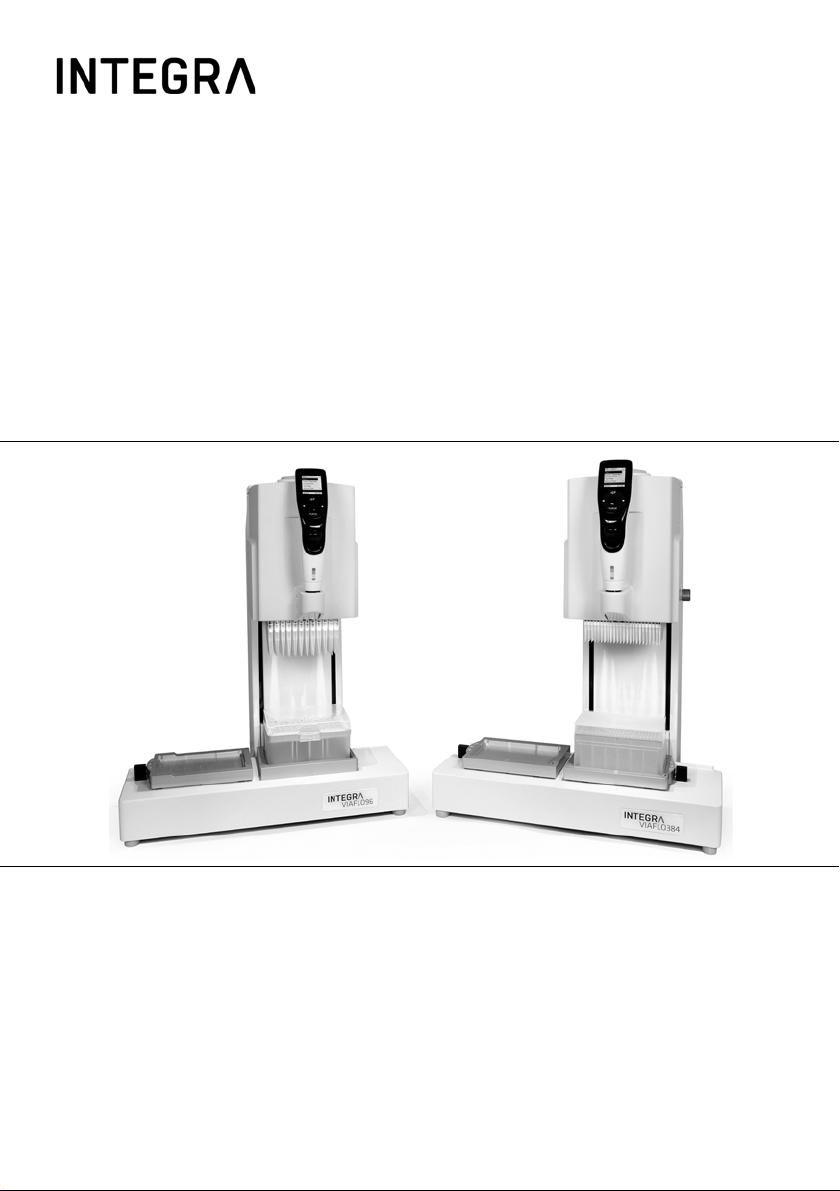
VIAFLO 96/384 is an electronic 96/384-channel hand held pipette designed for aspirating
and dispensing aqueous solutions in the volume range of 0.5 µl to 1250 µl using GripTip
pipette tips. VIAFLO 96/384 is used like a hand held pipette. The movement and
positioning of the 96-/384-channel pipette is supported by a servo assisted steering
mechanism which allows fast, precise and stress free multichannel pipetting. VIAFLO 96
can only be used with 96-channel pipetting heads, while VIAFLO 384 is compatible to both
96- and 384-channel pipetting heads.
www.integra-biosciences.com 7
Page 8
VIAFLO 96/384 – Operating instructions V11 Introduction
If VIAFLO 96/384 is used in a manner not specified by INTEGRA Biosciences, the
protection provided by the VIAFLO 96/384 may be impaired.
1.3 Safety notes
VIAFLO 96/384 complies to the recognized safety regulations and is safe to operate.
VIAFLO 96/384 can only be operated when in perfect condition and while observing these
operating instructions.
The device may be associated with residual risks if it is used or operated improperly by
untrained personnel. Any person operating the VIAFLO 96/384 must have read and
understood these operating instructions, and particularly, the safety notes, or must have
been instructed by supervisors so that safe operation of the device is guaranteed.
ARNING
W
Do not use the VIAFLO 96/384 near flammable material or in explosive
areas. Also, do not pipette highly flammable liquids such as acetone or ether.
When handling dangerous substances, comply with the material safety data
sheet (MSDS) and with all safety guidelines such as the use of protective
clothing and safety goggles.
AUTION
C
Do not immerse the pipetting head in liquid. The fluid can damage intern al
parts. Avoid pipetting of liquids whose vapors could attack the materials PA
(polyamide), POM (polyoxymethylene), FPM (fluor-rubber), NBR (nitrilerubber), CR (chloroprene), silicone. Corrosive vapors could also damage
metallic parts inside the device.
Do not open or modify VIAFLO 96/384 in any way . Th e sheet m eta l must not
be removed. Repairs may only be performed by INTEGRA Biosciences AG
or by an authorized after-sales service member.
Parts may be replaced with original INTEGRA Biosciences parts only.
Never insert the mains adapter of any INTEGRA electronic hand pipette into
the power connector of the control unit (5
NOTE
Prolonged exposure of the VIAFLO 96/384 to UV-light can cause
discoloration and/or yellowing of the control unit. However, this will not affect
the performance of the device in any way.
Regardless of the listed safety notes, additional applicable regulations and guidelines of
trade associations, health authorities, trade supervisory offices, etc. must be observed.
Please visit our website www.integra-biosciences.com
information regarding REACH classified chemicals contained in our products.
).
on a regular basis for up to date
8 INTEGRA Biosciences AG
Page 9
VIAFLO 96/384 – Operating instructions V11 Description of the device
4
5
8 A
8 B
10
6
1
2
9
3
7
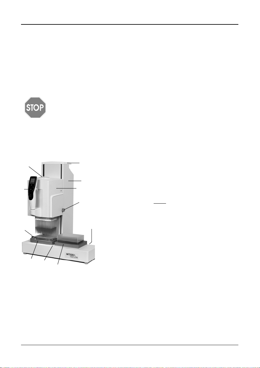
2 Description of the device
2.1 Scope of delivery
• VIAFLO 96/384 device
• Power cable
• USB cable type A to B
• Operating instructions
AUTION
C
Verify the scope of delivery when unpacking the device and check for
potential transportation damage. Do not operate a device that is damaged,
instead contact your local dealer.
2.2 Overview of VIAFLO 96/384
2.2.1 VIAFLO 96/384 device
1 Base unit, to move left and right (X axis)
2 Carrying handle of base unit
3 Pipetting unit, to move up and down (Z axis)
4 Tip load button
5 Control unit, see 2.2.2
6 Knob of Side cover, covers the pipetting head
7 Instrument deck
8 Plate holders on position A and B
9 Plate slider, with front (384), zero (96) and back
(384) position to index 96 or 384 well plates (Y axis)
10 Main switch
www.integra-biosciences.com 9
Page 10
VIAFLO 96/384 – Operating instructions V11 Description of the device
11
12
15
13
14
19
Current mode
Active step
OK
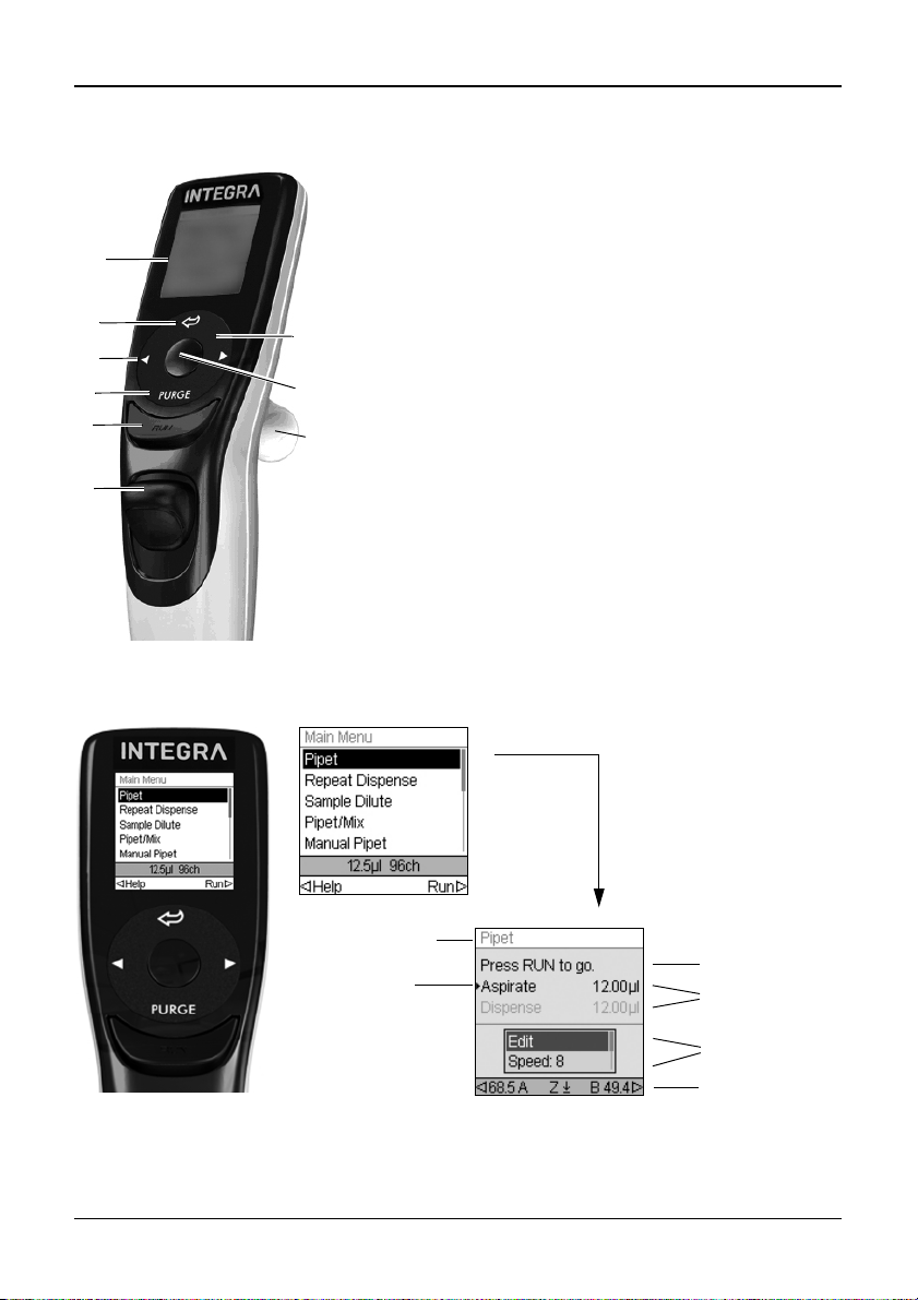
2.2.2 VIAFLO 96/384 control unit
11 Display
12 Back button, to navigate backward
13 Touch wheel, spin to scroll and move the cursor
14 OK button, to make a selection
15 Left and right arrow buttons, for selections
16 PURGE button, to empty tips
17 RUN key, to start operations
18 Tip ejector
19 Finger hook, facilitates easy operation
2.2.3 Display
The Display shows all pipetting options.
10 INTEGRA Biosciences AG
Instruction
Volumes
Options
Arrow buttons
to set Z height
Page 11
VIAFLO 96/384 – Operating instructions V11 Description of the device
2.2.4 Touch wheel
The Touch wheel is fully operational with only one hand. Rotational finger movements
translate into up and down cursor movement on the display. The Touch wheel is fully
functional with the use of latex gloves.
Move finger on the Touch wheel to choose (and
highlight) an option on the display. Press OK (14
make the selection.
When a setting dial is displayed, spin the Touch wheel
to change the value and press OK.
2.2.5 Left and right arrow buttons
At times, you will see and on a display screen. These buttons
are used to select options.
Press to select the option indicated with the left arrow (HELP, in
the example beside). Press to select the option indicated with the
right arrow (RUN, in the example).
2.2.6 PURGE button
During pipetting, you can interrupt the current pipetting protocol and purge all remaining
liquid currently in the GripTips. To do so, press PURGE (16
).
) to
The pipette will display a prompt.
To proceed, press and release the RUN key (17
of the dispense, the first step in the current program will be
displayed.
2.2.7 RUN key
Press and release the RUN key (17
special pipetting operations.
During dispense, you can press and hold the RUN key to perform a two-step blowout, see
Blowout modes” on page 23.
“4.3.3
www.integra-biosciences.com 11
) to initiate aspiration, dispense, mix, purge, and
). Upon completion
Page 12
VIAFLO 96/384 – Operating instructions V11 Installation
2
7
3 Installation
3.1 Operating environment
VIAFLO 96/384 has been designed for use in a laboratory. It shall be operated in a dry and
dust-free location with a temperature of 5– 40 °C and a maximal (non-condensing) relative
humidity of 80 %.
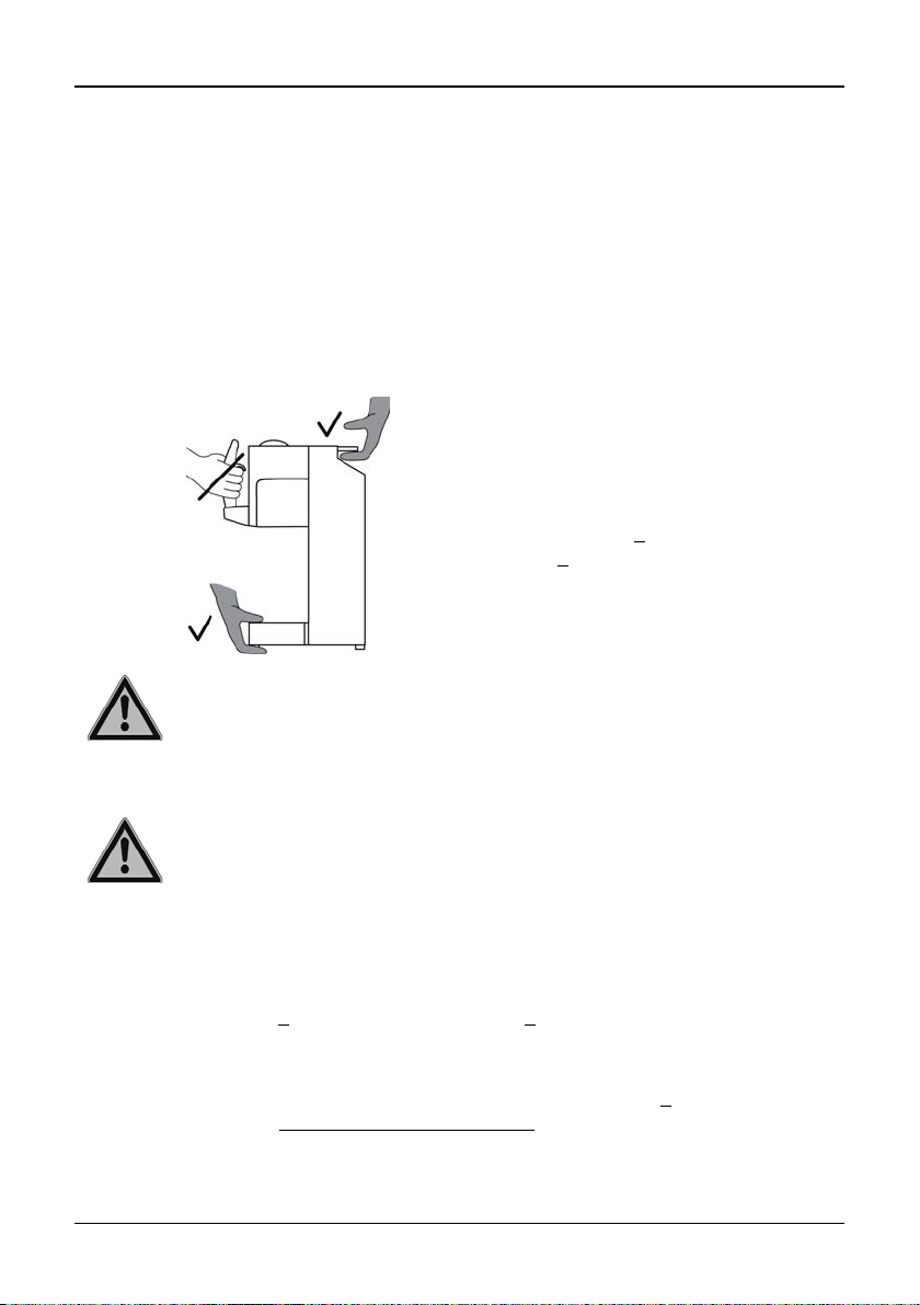
3.2 Setting up and moving of the instrument
The VIAFLO 96/384 must be set up on a cleaned, dry and horizontal surface.
.
Hold the Carrying handle (2
Instrument deck (7
) to lift VIAFLO 96/384.
) and the
WARNING
The device must not be carried on the control unit because it will be
damaged.
Leave at least 5 cm of free space on the back for air circulation and to allow easy
connection of the mains cable.
ARNING
W
It must always be possible to manually disconnect the plug of the VIAFLO 96/
384 from electricity supply. The corresponding socket shall be within easy
reach of the operator and be clearly labeled as the disconnecting device of
VIAFLO 96/384.
Only use a 3 core mains cable with protective earth to connect VIAFLO 96/384 with the
power source. The socket is located on the reverse side of the instrument deck.
Put the Plate holders (8
) on the Instrument deck (7) on Position A and/or B. They can
both be placed on either side. Move the Plate holder from left to right until the two bolts
click into the two holes.
Alternatively, put the three position stage on the Instrument deck (7
) until the bolts click
into the four holes, see “8.1 Accessories” on page 55).
12 INTEGRA Biosciences AG
Page 13

VIAFLO 96/384 – Operating instructions V11 Installation
WARNING
VIAFLO 96/384 must be secured with the “Park Head” function before
carrying.
Before VIAFLO 96/384 can be relocated, the pipetting and base unit must be fixed. Select
“Park Head” from “Calibration & Service” of the Toolbox menu, see “3.4.5 Calibration &
Services” on page 18. Make sure GripTips have been ejected, clear the Instrument deck
(7
) and press the RUN key (17) to start the park routine. The unit moves to the park
position and is anchored on the base with a bolt. Switch off VIAFLO 96/384 and
disconnect it from the electricity mains.
3.3 Getting started
Turn on VIAFLO 96/384 (see "Turn on/off the device" on page 21). To adapt the device to
the appropriate applications, select the following functions of the Toolbox menu in this
order:
• Change head: Select the toolbox menu “Change head” and insert the appropriate
pipetting head, see "
• Load 96/384 GripTips, see "Attaching and removing GripTips" on page 21
• Position settings - Head alignment: Define the center of the wells of a 96-or 384-well
plate, see "
• Position settings - Tip align: VIAFLO 96/384 base unit can be moved left and right
(X direction). Tip align locks onto the wells of a plate and helps to guide the tips into the
microplate wells.
• Z-Height: VIAFLO 96/384 pipetting unit can be moved up and down (Z direction). A
minimum height can be defined in every pipetting mode, e. g. to set optimal tip immersion depth, see “4.3.2
• Preferences: Define system parameters, see "Preferences" on page 16.
Position Settings" on page 16.
Change head" on page 14.
Set Z-Position” on page 23.
www.integra-biosciences.com 13
Page 14
VIAFLO 96/384 – Operating instructions V11 Installation
3.4 Toolbox - adapt your VIAFLO 96/384
The Toolbox provides options to adapt the device to appropriate applications, setting
personal preferences, calibration, computer connectivity and storing owner information.
Toolbox mode Description
Change Head Allows to change the pipetting head.
Position Settings Sets the tip alignment, head alignment and Z-height.
Preferences Customizes the system parameters.
Calibration & Service Sets calibration and service history options and parks the head.
Communications Enables communication between your VIAFLO 96/384 and a
PC.
Device Information View your pipette’s serial number, software version and set a
personal ID.
Language Sets display language.
Write Protect Protects programs or menu options from modification.
The Help information describes the modes and some settings, press to select the Help
option.
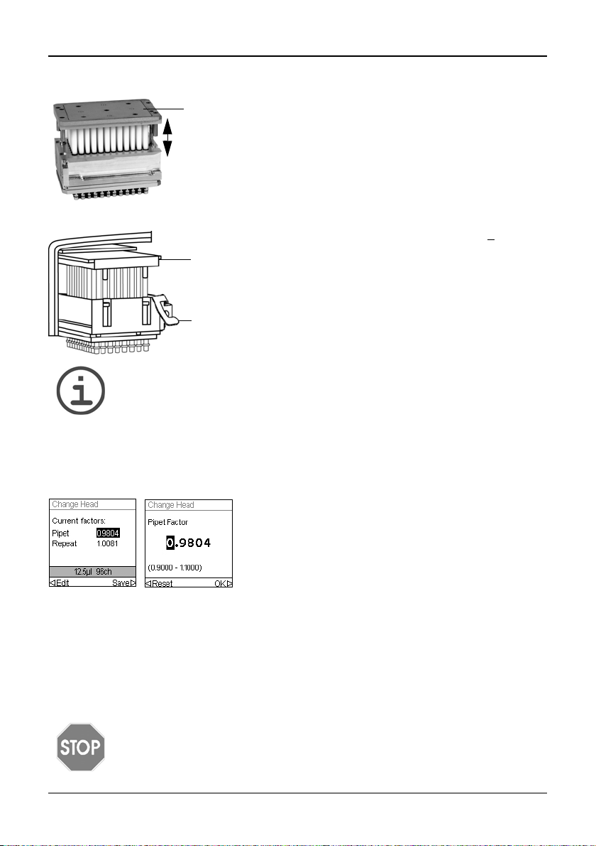
3.4.1 Change head
N
OTE
VIAFLO 96 can only be used with 96-channel pipetting heads, while VIAFLO
384 is compatible with both 96- and 384-channel pipetting heads.
The following pipetting heads are available:
Pipetting head Channels Volume range
12.5 µl 96 0.5–12.5 µl
50 µl 96 2–50 µl
125 µl 96 5–125 µl
300 µl 96 10–300 µl
1250 µl 96 50–1250 µl
12.5 µl 384 0.5–12.5 µl
50 µl 384 2–50 µl
125 µl 384 5–125 µl
14 INTEGRA Biosciences AG
Page 15
VIAFLO 96/384 – Operating instructions V11 Installation
a
a
b
Remove the pipetting head from the case.
Make sure the pipetting head is in extended position (see
image to the left). If necessary, pull apart the Piston plate
(a) on the top as far as possible.
To install the appropriate pipetting head select the Toolbox option “Change Head”.
Loosen the knob and remove the Side cover (6
Remove the existing head, if installed.
Push the appropriate pipetting head into the slide block
and make sure the Piston plate (a) slides onto the
brazen rails.
Mount the Side cover, screw the knob tightly and press
OK to continue.
OTE
N
Pipetting heads with a serial number >50274 feature an ejection lever (b) to
facilitate the removal of the head. Pull up the lever to loosen the pipetting
head, then remove it from the instrument.
Check whether the Pipet factor on the display corresponds to the Pipet factor labeled on
the side of the head itself or indicated in the latest calibration certificate. Press OK if the
factors coincide. If they don't, click Edit.
).
With the factor “Pipet” selected click Edit to change
the Pipet factor accordingly. Using the Touch Wheel,
select the digit to be modified, then press OK and use
the Touch Wheel to select a number. Press OK to
confirm. Once finished, press Save to apply the
correct Pipet factor to the instrument.
Reset sets the factor to 1.0000. Changing the factor “Repeat” is only necessary under
special circumstances. Refer to the calibration document (PROTO_VIAFLO96_384_
calibration), available on request.
3.4.2 Storage of pipetting heads
Once a pipetting head is removed from VIAFLO 96/384 it must be stored in the appropriate
casing to protect it from dust and mechanical damage.
AUTION
C
Pipetting heads with 384-channels must always be stored in extended
position.
www.integra-biosciences.com 15
Page 16

VIAFLO 96/384 – Operating instructions V11 Installation
3.4.3 Position Settings
Position settings contain options that help to find correct pipetting positions. These
settings are globally stored and are valid for all pipetting heads. Perform these alignments
with GripTips attached, see “4.2 Attaching and removing GripTips” on page 21.
Position
settings
Tip Align Optimally aligns the tips to target the center of the wells
Head Alignment
Z Height Activate to enable overriding of the defined Z-height.
Description Range
on a 96-or 384-well plate.
•Select Position A or B and press OK to activate the tip
alignment.
• Highlight the Strength option and press OK. Set align-
ment support strength 1 (low) to 3 (high). Press OK.
• Column Detent activates column positions of a plate
on Position A or B, e. g. for serial dilutions. Press OK.
Press to save.
Use a 96 well plate for a 96-channel and a 384-well plate
for a 384-channel pipetting head to define the center of
the wells. This setting is required only once per pipetting
head. Move the unit to Position A or B until the selected
position, e.g. A, is displayed.
• Move the unit down and align the tips to the center of
the wells. Select Set to save this position.
• Repeat at position B.
Keep pushing down the control unit to overcome the Zheight, see “4.3.2
Set Z-Position” on page 23.
/
(On/Off)
1-3
(Off)
(A or B)
-
/
(On/Off)
3.4.4 Preferences
Preferences customizes your system parameters. Select an option and press OK to
access. After changing desired settings, press to Save.
Preferences
Deck Brightness
16 INTEGRA Biosciences AG
Description Range
Sets brightness of deck illumination.
• Use the Touch wheel to change the brightness:
off, 1 (weak) to 10 (bright). Press OK.
Off
1-10
Page 17
VIAFLO 96/384 – Operating instructions V11 Installation
Handle Sensitivity
Sound Select an option and press OK to change the status of
Display
Brightness
Main Menu Select a function to be hidden from the main menu (Off)
Touch
Wheel
Pipetting Select an option and press OK.
Sets the sensitivity of the control unit to move the
pipetting unit and base unit.
• Use the Touch wheel to set a sensitivity 1 (low) to 9
(high). Press OK.
the beep tone between On and Off:
• Step Complete: at the end of a program step
• Program Complete: at program completion
• Purge Key: when PURGE is pressed.
• Messages: when a message appears.
• Error Message: when an error message appears or
when illegal data entry is attempted.
• Touch Wheel: When spinning the Touch wheel.
• Last dispense: before the last dispense in Repeat
Dispense and Variable Dispense.
Sets brightness of the display. Use the Touch wheel to
change the brightness: 1 (dim) to 10 (bright). Press OK.
and press OK:
• Pipet, Repeat Dispense, Dilute, Pipet/Mix, etc.
• The Automatic mode is by default deactivated. To activate it, change the status to “” (On). See section 5.3.3
for a description of the Automatic mode.
Adjust your Touch wheel spin sensitivity. Low, Medium,
• Purge Key Speed: Choose the desired purge speed.
• Blowin Delay: Choose a timed delay between the
blowout and the blowin at the end of a dispense, if no
two step blowout is performed, see “4.3.3
modes” on page 23.
• Extend Volume (not available for 12.5 µl pipetting
head): For pipetting below the volume range specified:
50 μl pipette: (1.0)–2–50 μl
125 μl pipette: (2.0)–5–125 μl
300 μl pipette: (5.0)–10–300–(310) μl
1250 μl pipette: (25)–50–1250 μl
The volumes in brackets refer to extended volumes,
e.g. extend the minimal pipetting volume of a 125 μl
head from 5 μl to 2 μl.
NOTE
Extending the volume range is not recommended. Full functionality and
specified accuracy/precision cannot be guaranteed.
Blowout
1-9
/
(On/Off)
1-10
/
(On/Off)
High
1-10
None/
0.5-5.0 s
/
(On/Off)
www.integra-biosciences.com 17
Page 18

VIAFLO 96/384 – Operating instructions V11 Installation
3.4.5 Calibration & Services
These options enable you to set calibration features, review service history and move the
pipetting head into the parking position.
Calibration
& Services
Calibration Allows for re-calibration of VIAFLO 96/384 to restore
Calibration
Reminder
Service History
Park Head Fixes the pipetting and base unit for safe transportation.
After changing desired settings, press to Save.
Description Range
accuracy. The calibration factors for Pipet and Repeat
type are displayed.
To edit the calibration volumes, press .
• Target Volume: This is the volume you are interested
in using for the calibration.
• Actual Volume: This is the measured volume obtained
when dispensing the target volume.
• Current Factor: Displays the factor currently in use.
This factor should be the same as specified on the
head or the latest calibration certificate.
• Reset: Resets the correction factor back to the original factory setting. Press to apply the factory setting.
Sets a calibration reminder based on a number of
pipetting cycles. When the calibration reminder is
displayed, press any key to confirm. However, the
reminder will reappear every time the pipette is turned on
until you change the reminder time or use the reset
option.
• Reminder: Press OK to turn the reminder timer On or
Off.
• Cycles: Use the Touch wheel to set a reminder inter-
val for calibration (time in thousands of cycles). Press
to set the timer to the defined calibration interval.
• Remind in/Total Cycles: Displays the residual amount
of cycles before calibration is required.
• Reset: Resets the timer to the defined calibration
interval. Press to enable.
Press to save.
Displays notes of any service that took place on the
VIAFLO 96/384 listed newest entry first.
• Make sure GripTips are ejected, clear the deck and
press the RUN key to start the park routine. The
pipette moves to park position and can then be turned
off.
-
/
(On/Off)
1k - 240k
cycles
-
-
18 INTEGRA Biosciences AG
Page 19

VIAFLO 96/384 – Operating instructions V11 Installation
3.4.6 Communications
VIAFLO 96/384 can be programmed from a PC via USB communication cable (type A to
B).
Communications
VIALINK Connect the USB cable betweenVIAFLO 96/384 and a PC. Press OK to
3.4.7 Device Information
Device
Information
VIAFLO 96/
384
In addition, information about your VIAFLO 96/384, such as serial number, the firmware
(FW) and hardware (HW) version of the control unit and of the base unit are displayed.
3.4.8 Language
Language Description
Language You can choose the language in which all screens are displayed. Scroll to
Description
begin bi-directional communication. To exit the communications mode
turn off VIAFLO 96/384.
Description
Owner: Press to enter the user name for your pipette. Use the Touch
Wheel to highlight a character and press OK. You can press to Delete
the last character entered. After entering the desired text, press to
Save.
the desired language, press OK and to Save.
www.integra-biosciences.com 19
Page 20

VIAFLO 96/384 – Operating instructions V11 Installation
3.4.9 Write protect
Select this option to protect programs and menu options from inadvertent modification.
The pipetting programs can still be used.
Write
protect
Keep the password in a safe place. Should you lose your password, contact
INTEGRA Biosciences to retrieve your password.
Description Range
Select an option and press OK to switch protection on or
off:
• Standard Programs
• Custom Programs
• Calibration
• Too lbo x
• Password Protection: Protect the access to the write
protect menu by selecting “”.
• Edit Password, if password protect is switched on. To
enter a password use the Touch wheel to highlight a
character and press OK. Press to save the password. The password must be entered before you can
access the write protect menu.
/
(On/Off)
20 INTEGRA Biosciences AG
Page 21

VIAFLO 96/384 – Operating instructions V11 Operation
4 Operation
4.1 Turn on/off the device
Turn on:
AUTION
C
Remove hands from Control unit (5) at switch on and during homing.
When VIAFLO 96/384 is turned on by the Main switch (10), you are prompted to press
the RUN key (17
Press the RUN key again to home the pipetting unit. If filled tips are still on the device, put
a basin below the pipetting head. After homing the Main menu is displayed.
Turn off:
To turn off VIAFLO 96/384, press the Main switch (10
4.2 Attaching and removing GripTips
) to perform a vertical and horizontal homing routine.
).
NOTE
VIAFLO 96/384 automatically goes into stand-by after 30 minutes of
inactivity.
Press OK to continue.
CAUTION
To ensure optimal performance of your VIAFLO 96/384, use only GripTips
designated for use with VIAFLO 96/384, see “8 Accessories and
consumables” on page 55. To prevent contamination of VIAFLO 96/384
pipetting heads, it is recommended to use filtered GripTips only.
NOTE
When using 12.5 µl or 125 µl GripTips with a 96-channel pipetting head, put
the tip box on a Plate holder with slide function and move the Plate slider
) to a 384 position, see “4.4.7 Pipetting between 96 and 384 well plates” on
(9
page 28.
4.2.1 Loading tips from a complete box
Put a tip box either on the left or right Plate holder (8). Hold the Control unit (5) and lower
the pipetting head down onto the tip box until the Tip load button (4) flashes.
www.integra-biosciences.com 21
Page 22

VIAFLO 96/384 – Operating instructions V11 Operation
a
b
When prompted push the Tip load button (a) and at the
same time push down the Control unit (b).
When the tips are loaded, the Tip load button lights up.
) up until the light of the Tip
4.2.2 Partial tip loading
C
AUTION
If only one tip column should be loaded, reduced loading force is required.
Move the Pipetting unit (3
load button turns off.
Put a tip box either on the left or right Plate holder (8
). Hold the Control unit (5) and lower
the pipetting head down onto the tip box until the Tip load button (4) flashes.
When prompted to push the Tip load button, first press OK (14
) to switch to “low power”
loading mode. Then push Tip load button while pushing down the Control unit until the
Tip load button lights up.
Move the Pipetting unit (3
) up until the light of the Tip load button turns off.
4.2.3 Ejecting used GripTips
If liquid is in the tips, empty them by pressing the PURGE button (16
by pressing the Tip ejector (18
). Confirm ejection by pressing the Tip ejector a second
). Tips are ejected
time.
22 INTEGRA Biosciences AG
Page 23

VIAFLO 96/384 – Operating instructions V11 Operation
4.3 Start pipetting
4.3.1 Pipetting
Use the Touch wheel (13
Actions you are about to perform will be displayed on the Run screen.
) to scroll to your desired pipetting mode and press OK (14).
Insert the tips into the liquid to be transferred. Press
and release the RUN key (17) to aspirate the volume
selected in the first step of your protocol (shown on
the Run screen).
To execute subsequent steps, press the RUN key.
For a detailed description of all pipetting modes see “5.2
modes” on page 32. You can change the parameters of your pipetting mode at any time,
see the following sections.
4.3.2 Set Z-Position
To define the optimal tip immersion depth, press or to access the Z-position
screen.Then move the pipetting unit to the target position (A, B) until the actual Z-height
and the current setting are displayed.
• Move the unit down to the desired dispensing height, e.g. 31 mm.
Select Set to enter this position and save your setting.
• Repeat this procedure with position B.
4.3.3 Blowout modes
During the last dispense of a program, a blowout is performed automatically to ensure
efficient liquid delivery. Liquid may be aspirated back into the tips when the pistons move
back to the home position, a process called blowin. There are two ways to perform the
blowin:
• Automatic blowout: Pressing (and releasing) the RUN key starts the dispense with
automatic blowout and blowin. You can choose a timed delay between the blowout and
the blowin, see “Pipetting - Delayed blowin” under “3.4.4
• Two-step automatic blowout: Perform a two-step blowout to manually delay the
blowin:
- Press and hold
- Remove the tips from the target vessel.
- Release the RUN key to start blowin.
the RUN key to start dispense with blowout.
Detailed description of pipetting
Preferences” on page 16.
www.integra-biosciences.com 23
Page 24

VIAFLO 96/384 – Operating instructions V11 Operation
4.3.4 Recommendations for pipetting
INTEGRA Biosciences recommends the following techniques for enhancing pipetting
results. These techniques are consistent with ISO standard 8655-2.
• It is best to immerse the GripTips just enough in liquid to allow the desired volume to be
aspirated.
• Always pre-wet GripTips. After loading tips onto your pipette, aspirate and dispense the
full volume 2-3 times to coat the inside of pipet tips. Pre-wetting ensures that the liquid
and air inside the tips are at equal temperature and the dead air space is humidified.
• VIAFLO 96/384 is an air displacement pipette. It requires to touch the GripTips against
the side of the well or dip them into the liquid after a dispense. This process is referred
to as “touching off” or “tip touch” and prevents liquid from clinging to the pipette tips.
• In programs such as Repeat Dispense, a first and last dispense can be programmed.
These two dispenses are not used and are dispensed into the waste as they contain the
accumulated pipetting errors. Using a first and last dispense is recommended if
accuracy and precision are of high importance.
• Viscous samples should be aspirated and dispensed at the slowest speeds to ensure
accurate pipetting. In addition, the pipetting mode “Reverse pipet” can be used to
optimize pipetting results with viscous samples.
• For pipetting liquids with high vapor pressures (such as methanol or ethanol), use
relatively fast pipetting speeds and avoid prolonged pauses after aspiration.
• Calibrate based on fluid type. VIAFLO 96/384 is tested and calibrated at the factory for
use with distilled water at room temperature. It may be necessary to re-calibrate your
VIAFLO 96/384 if the liquid to be used has different physical properties (specific gravity
and vapor pressure) than water. Calibration mode can be accessed in the Toolbox
menu.
ARNING
W
Avoid pipetting for extended periods. To minimize the risk of repetitive strain
injury, include regular pauses of several minutes.
24 INTEGRA Biosciences AG
Page 25

VIAFLO 96/384 – Operating instructions V11 Operation
4.4 Pipetting options and settings
4.4.1 Edit option
The Edit option is available for each mode. It enables you to access the variables that you
can adjust for a pipetting mode. These variables include Speed, Volume, Pace, Count, Mix
Cycles, Rows and Direction. Additional steps include First Dispense, Last Dispense, Air
Gap, Aspirate Speed, Dispense Speed, etc..
Select a pipetting mode. Then, select Edit on the list
of options and press OK. A list of associated steps is
displayed. For example, if selecting Edit on the
Repeat Dispense screen, the modifiable steps
associated with Repeat Dispense are displayed.
4.4.2 Volume selection
To change a volume select the Edit option and press OK. The adjustable volumes are
displayed.
Use the To u ch wheel to highlight the volume you
want to change (Aspirate, Dispense, Mix, or Air Gap).
Press OK and a Volume setting “dial” is displayed.
Use the Touch wheel to change the volume. Press
OK to confirm your volume selection and to save.
OTE
N
Use the arrow buttons to change the volume in coarse or fine incre ments.
Select Coarse to change the volu me in larger increments. Select F ine
to change the volume in smaller increments. The increment sizes vary based
on the pipetting head, as shown under “7.4
page 54.
www.integra-biosciences.com 25
Pipetting specifications” on
Page 26

VIAFLO 96/384 – Operating instructions V11 Operation
Define and select favorite volumes
You can define, save, and select up to ten favorite volumes for quick access. These
volumes can only be within the pipetting head volume range.
There are two ways to access and customize the list of favorite volumes:
• When in Pipet mode, use the Touch wheel to highlight Favorites and press OK.
• When in other modes, select the Edit option and press OK. The steps with volumes to
be adjusted are displayed. Use the Touch wheel to highlight the desired volume and
press Favorites to display the list of favorite volumes.
Use the Touch wheel to highlight the desired volume
and press Select. Alternatively, modify a volume
by pressing Edit.
Save your setting .
4.4.3 Speed selection
The speed option controls the speed at which liquid is aspirated, dispensed, or mixed in
each mode. Speed can be set as a value from 1 (slowest) to 10 (fastest).
When in any pipetting mode, use the Touch wheel to
highlight the Speed option and press OK. Select the
speed and press OK to save your setting.
Speed may be changed in most
Edit menus. Scroll to the Speed and
press OK. Choose the speed,
press OK, and press to save
your selection.
The speeds selected in each mode (i.e., Pipet, Repeat Dispense, etc.) are stored for that
mode only.
Speeds can be set independently for each operation (Aspirate, Dispense, Mix).
OTE
N
Viscous samples should be aspirated and dispensed at the slowest speeds
to ensure accurate pipetting.
To dispense liquids with low viscosity and high vapor pressure, such as
ethanol, use relative fast pipetting speeds and avoid prolonged pauses for
aspiration.
26 INTEGRA Biosciences AG
Page 27

VIAFLO 96/384 – Operating instructions V11 Operation
4.4.4 Custom
You can convert any predefined pipetting mode into a Custom program.
After setting up a pipetting mode with your
parameters, use the Touch wheel to select
Custom.
You are prompted to enter an name. Use the To uch
Wheel to select characters and press OK. Once
finished, press to save the name.
The program is now stored in the Custom program section.
4.4.5 Pace
The Pace option sets the time gap between dispenses in repeat pipetting. Pace is used in
the Repeat Dispense and Variable Dispense modes. While you press and hold the RUN
key, the pipette will dispense multiple programmed volumes with the selected pace.
Release the RUN key to stop the paced dispense. Press the RUN key to continue
dispensing.
Use the Touch wheel to select the desired Pace
option and press OK.
Select the pace, from None, 1 (slowest) to 9 (fastest).
Press OK to save your setting.
4.4.6 Count, Mix Cycle and Rows
The Count, Mix Cycle, and Rows steps are used in various modes, see “5.2
description of pipetting modes” on page 32. Each is accessed with the Edit option. Use
the Touch wheel to highlight the step and press OK.
Count sets the number of dispensing steps. Mix Cycle sets the number of mixes. In serial
dilution mode, Rows sets the number of rows. A row indicator will notify the number of
dilutions performed. Rows (first number) and Mix Cycles (second number) are tracked on
the display. Mix Cycles are shown in red when mixing. A green dot on the row number
indicates the active program step.
Select a desired value. Press OK and then press to save your setting(s).
www.integra-biosciences.com 27
Detailed
Page 28

VIAFLO 96/384 – Operating instructions V11 Operation
384
384
96
4.4.7 Pipetting between 96 and 384 well plates
For fast and simple reformatting between 96 and 384 well microplates and for loading of
12.5 or 125 µl GripTips with a 96-channel pipetting head, some Plate holders feature a
slide function to shift the microplate in Y-direction beneath the pipetting head. Put this
Plate holder, accommodating the 384 well plate, either on Position A or B (8). Move the
Plate slider (9
) to one of the following 3 positions:
The back position of the Plate slider is used to
accommodate the front positions of 384 well plates.
For pipetting the second columns move the pipetting
head one well to the right, or left respectively.
The front position of the Plate slider accommodates the
back positions of 384 well plates.
For pipetting the second columns move the pipetting
head one well to the right, or left respectively.
Set the Plate slider to the middle to pipet 96 well plates.
28 INTEGRA Biosciences AG
Page 29

VIAFLO 96/384 – Operating instructions V11 Operation
a
4.4.8 Pipetting with the three position stage
The three position stage (see “8.1
of three possible positions.
Use the Stage slider (a) to accommodate the positions of 384 or 96 well plates as
described in 4.4.7
.
Accessories” on page 55) supports the pipetting on two
Move the three position stage to
the right to pipette on position A
and AB.
Move the three position stage to
the left to pipette on position AB
and B.
www.integra-biosciences.com 29
Page 30

VIAFLO 96/384 – Operating instructions V11 Operation
4.5 Troubleshooting/FAQ
Problem Probable cause Remedy
Base unit is drifting
sidewards.
Touch wheel does
not work properly.
Menu options not
selectable (grayed
out).
Pipetting not possible.
Tips cannot be
loaded.
Tips are not centered in the wells,
although tip alignment is activated.
Droplets on the tips. Temperature of liquid differs
Obstruction error. Base unit moved in X direc-
Control unit was touched at
switch on.
Control unit was touched
during homing.
No pipetting head installed. Install a pipetting head.
Side cover missing or pipetting head not correctly
installed.
Z height defined too high
above the top of the box.
Head alignment was not performed yet.
from that of air inside the tips.
Liquid of low viscosity and
high vapor pressure.
Touch-off was not performed. Perform a touch-off (mandatory in
tion by hand.
Tips hit an obstacle during
X movement, e.g. box, container.
Guide rail soiled. Clean the guide rail for base unit.
Other causes. Switch the device off and on.
Do not touch the control unit when
switching on the VIAFLO 96/384.
Restart VIAFLO 96/384 to initiate
new homing routine.
Do not touch the control unit
during homing.
Restart VIAFLO 96/384 to initiate
new homing routine.
Ensure pipetting head is installed
correctly. Mount the side cover
and screw the knob tightly.
Exit the pipetting mode. Alternatively clear Z height setting on
position where tips are loaded.
Perform head alignment for every
pipetting head.
Pre-wet tips up to 3 times.
Pre-wet tips and increase dispensing speed.
Repeat Dispense and Variable
Dispense mode).
Always hold the control unit to
move the base unit sidewards.
Move the tips upwards to a height
that clears the tip rack out.
30 INTEGRA Biosciences AG
Page 31

VIAFLO 96/384 – Operating instructions V11 Pipetting modes
5 Pipetting modes
This chapter describes how to program the VIAFLO 96/384 in two ways:
• Function-based pipetting modes: You can select from ten predefined pipetting modes
that you can quickly and easily edit and execute. They are described in the
following sections.
• Custom step-based programming mode: You can create and store up to forty multistepped pipetting protocols on the pipette using the basic functions of
“Aspirate, Dispense, Mix, Purge, Prompt, Set Z Height, Tip Align and Loop” presented
in “5.2
Detailed description of pipetting modes” on page 32. The custom programming
mode is described in “5.3
5.1 Overview pipetting modes
The table below provides an overview of the selectable pipetting modes. All modes are
accessed from the Main Menu. Use the Touch wheel to scroll to your desired pipetting
mode.
Pipetting mode Description
Pipet Allows liquid transfers when aspirate and dispense volumes are
Repeat Dispense Allows dispensing multiple aliquots of the same volume without
Sample Dilute Allows aspirating of sample and diluent divided by a defined air
Pipet/Mix Transfers a defined volume and follows with a defined number of
Manual Pipet Allows the operator to manually control the aspiration and
Reverse Pipet Allows liquid transfers of viscous or high vapor pressure liquids
Variable Dispense Allows dispensing multiple aliquots of different volumes.
Variable Aspirate Allows aspirating multiple aliquots of different volumes.
Sample Dilute/Mix Allows aspirating two liquids separated by an air gap followed by
Serial Dilution Allows aspirating a transfer volume followed by a mix. Rows and
Custom Allows to create and store of up to 40 multi-stepped pipetting
Press the OK to access the pipetting mode and to start defining parameters. Press to
select the Help option.
Custom step-based programming mode” on page 41
equal.
refilling the tips after each dispense for fast microplate filling and
processing.
gap into one tip, followed by a complete dispense.
automatic mixing cycles.
dispensing up to the set volume.
by preventing introduction of any air into the sample. The
aspiration volume is higher than the volume to be dispensed.
a complete dispense and Mix step.
Mix Cycles are tracked on the display.
protocols.
www.integra-biosciences.com 31
Page 32

VIAFLO 96/384 – Operating instructions V11 Pipetting modes
5.2 Detailed description of pipetting modes
VIAFLO 96/384 offers ten predefined pipetting modes. Most liquid handling protocols can
be easily accommodated using one or more of these modes. The options and steps of the
different pipetting modes are described in the following subsections.
5.2.1 Pipet mode
Application: Use this mode for quick transfer of liquid to or from microplates.
Options Steps Description
Edit Aspirate Sets the aspiration volume that is equal to the dispense
volume.
Speed Sets speed for the current pipetting step (1 = low, 10 = fast).
Favorites Defines up to 10 favorite volumes
Custom Converts the predefined program into a custom program.
Operation:
• With the tip(s) in liquid, press and release the RUN key to aspirate.
• With the tip(s) in the destination plate, press and hold the RUN key to execute the
dispense and perform a two-step blowout, see “4.3.3
• When the tips are removed from the target plate, release the RUN key.
Blowout modes” on page 23.
32 INTEGRA Biosciences AG
Page 33

VIAFLO 96/384 – Operating instructions V11 Pipetting modes
5.2.2 Repeat dispense mode
Application: This mode can be used for fast reagent addition to microplates from one
source container. You can dispense a large aspirated volume of liquid in multiple aliquots
to multiple targets.
Options Steps Description
Edit Dispense Sets the volume for repetitive dispensing. The aspirated
volume is calculated automatically.
First
Dispense
Last Dispense A last-dispense volume can be selected independently to
Reuse Last
Disp.
Count The maximum number of dispenses possible (count) is
Asp. Speed Sets speed uniquely for aspirating (1 = slow, 10 = fast).
Disp. Speed Sets speed uniquely for dispensing (1 = slow, 10 = fast).
Speed Sets speed of the current pipetting step.
Pace Sets the time duration between dispenses in repeat pipetting,
Custom Converts the predefined program into a custom program.
Operation:
• With the tip(s) in liquid, press and release the RUN key to initiate the aspirate step.
• Press and release the RUN key for every dispense. Alternatively, press and hold Run
to execute paced dispenses. The dispense number is shown on the display.
• The pipette will stop paced dispenses when it reaches the Last Dispense. You can
choose to use this Last Dispense or discard it.
- If reuse of last dispense is not activated, press and hold the RUN key to purge the
Last Dispense volume with a two-step blowout.
- If reuse of last dispense is active, you can start the next repeat dispense cycle with
aspirating liquid to the last dispense in the tip. To finish the repeat dispense cycle,
press PURGE.
A pre-dispense volume can be selected independently to
improve accuracy and precision. The dispense is discarded.
improve accuracy and precision. The dispense is discarded.
By default (red ), the mode ends with dispensing of the last
dispense. This aliquot contains the accumulated error from all
prior dispenses.
If you want to reuse the last dispense, press OK (green ).
At the end of the program the last dispense remains in the tip,
while the pipette is ready to aspirate a new volume to start the
next repeat dispense run.
calculated automatically. This count may be reduced to the
desired number.
if keeping RUN key pressed (1 = long, 9 = short).
www.integra-biosciences.com 33
Page 34

VIAFLO 96/384 – Operating instructions V11 Pipetting modes
5.2.3 Sample dilute mode
Application: Accomplish accurate sample dilutions by using diluent to “chase” small
sample volumes from the pipet tips. An air gap keeps liquid separated in the tips and helps
to minimize carryover of diluent when aspirating the sample.
Options Steps Description
Edit Aspirate 1 Sets the volume of the diluent aspirated first in the tip.
Air Gap Sets the volume of the air gap to keep both liquids separated.
Aspirate 2 Sets the volume of the sample in the tip.
Asp. Speed Sets speed uniquely for aspirating (1 = slow, 10 = fast).
Disp. Speed Sets speed uniquely for dispensing (1 = slow, 10 = fast).
Speed Sets speed of the current pipetting step.
Custom Converts the predefined program into a custom program.
Operation:
• Press and release the RUN key to initiate each aspiration (remove tips from liquid for
air-gap aspiration).
• Press and hold the RUN key to perform a two-step blowout. The entire tip contents will
be dispensed together.
5.2.4 Pipet/mix mode
Application: Use this mode when mixing is required immediately after transfer of liquid.
This mode saves a programming step by incorporating the mix option after dispensing.
Options Steps Description
Edit Aspirate Sets the aspiration volume that is equal to the dispense
volume.
Mix Sets the mixing volume after dispensing.
Mix Cycles Sets the number of mix cycles.
Asp. Speed Sets speed uniquely for aspirating (1 = slow, 10 = fast).
Mix Speed Sets speed uniquely for mixing (1 = slow, 10 = fast).
Speed Sets speed of the current pipetting step.
Custom Converts the predefined program into a custom program.
Operation:
• Press and release the RUN key to initiate the aspiration.
• Press and release the RUN key to dispense. Mixing occurs automatically after the
dispense step.
• Upon completing the desired number of mixes, a blowout is initiated automatically
prompting you to remove the tip(s) from the liquid and press the RUN key to complete
the blowout.
34 INTEGRA Biosciences AG
Page 35

VIAFLO 96/384 – Operating instructions V11 Pipetting modes
5.2.5 Manual pipet mode
Application: This mode can be used when the aspiration volume is not defined or
unknown. You have control over the aspiration and dispense steps and can view the
display to confirm how much liquid has been aspirated or dispensed. Manual control over
the dispense steps is perfect for performing titrations or for controlling the loading of
samples in gel lanes.
Options Steps Description
Edit Aspirate Sets the aspiration or dispensing volume. Toggle between
Aspirate and Dispense using the Direction menu option.
Speed Sets speed of the current pipetting step (1 = slow, 10 = fast).
Direction Changes the direction of pipetting between aspiration ()
Favorites Defines up to 10 favorite volumes
Operation:
• When aspirating, the motor will stop when you release the RUN key or when the
programmed aspirate volume is reached.
• You can change pipetting direction at any time even if aspiration volume is not reached.
Change the direction of pipetting by pressing OK on the Direction option. The notation
on the display changes between (Aspirate) and (Dispense).
• The volume remaining in the tip(s) is displayed.
N
OTE
Use slower pipetting speeds (1-5) for better control and resolution.
and dispensing ().
www.integra-biosciences.com 35
Page 36

VIAFLO 96/384 – Operating instructions V11 Pipetting modes
5.2.6 Reverse pipet mode
Application: With this mode the aspiration volume is higher than the volume dispensed.
It is recommended for liquid transfers of viscous and high vapor pressure liquids. The
dispense method prevents introduction of air into the sample because no blowout is made.
Options Steps Description
Edit Dispense Sets the dispense volume.
Last Dispense Sets the volume to leave in the tip until final blowout.
Reuse Last
Disp.
Asp. Speed Sets speed uniquely for aspirating (1 = slow, 10 = fast).
Disp. Speed Sets speed uniquely for dispensing (1 = slow, 10 = fast).
Speed Sets speed of the current pipetting step.
Custom Converts the predefined program into a custom program.
Operation:
• Press and release the RUN key to initiate the aspiration. The total volume aspirated is
the sum of desired dispense volume and last dispense volume.
• Press and release the RUN key to dispense the programmed volume.
• If reuse of last dispense is not activated, press and hold the RUN key to purge the Last
Dispense volume with a two-step blowout.
• If reuse of last dispense is active, you can start the next reverse pipet cycle with
aspirating liquid to the last dispense in the tip. To finish the reverse pipet cycle, press
PURGE.
By (red ) default, the mode ends with dispensing of the last
dispense.
If you want to reuse the last dispense, press OK (green ).
At the end of the program the last dispense remains in the tip,
while the pipette is ready to aspirate a new volume to start the
next reverse pipet run.
36 INTEGRA Biosciences AG
Page 37

VIAFLO 96/384 – Operating instructions V11 Pipetting modes
5.2.7 Variable dispense mode
Application: Use this mode when differing dispense volumes are required. This mode
could be used to quickly set up a dilution series in plates or for feeding similar samples to
different assay plates where different sample volumes are needed.
Options Steps Description
Edit Count Sets the total number of dispensing steps.
Asp. Speed Sets speed uniquely for aspirating (1 = slow, 10 = fast).
Disp. Speed Sets speed uniquely for dispensing (1 = slow, 10 = fast).
Dispense
1...Count
Speed Sets speed of the current pipetting step.
Pace Sets the time interval between dispenses, if keeping RUN
Custom Converts the predefined program into a custom program.
Operation:
• Press and release the RUN key to initiate the aspiration of total volume.
• Press and release the RUN key to initiate each subsequent dispense. The pipette stops
and beeps when ready for the Last Dispense step, i.e. to purge the calculated waste
volume amount.
• Alternatively, press and hold the RUN key to execute paced dispenses. The pipette
stops paced dispensing when it reaches the Last Dispense. This aliquot contains the
accumulated error from all prior dispenses. You can choose to use this Last Dispense
or discard it.
• During the Last dispense, press and hold the RUN key to perform a two-step blowout.
Sets different volumes for repeated dispensing. Number of
dispenses and dispense volume cannot exceed nominal
volume of the pipetting head. The total volume is
automatically calculated.
key pressed (1 = long, 9 = short).
www.integra-biosciences.com 37
Page 38

VIAFLO 96/384 – Operating instructions V11 Pipetting modes
5.2.8 Variable aspirate mode
Application: This mode can be used for a variety of collection applications where the
aspiration volume is well known. This mode is also suited for supernatant collection in
microplates.
Options Steps Description
Edit Count Sets the total number of aspirating steps.
Asp. Speed Sets speed uniquely for aspirating (1 = slow, 10 = fast).
Disp. Speed Sets speed uniquely for dispensing (1 = slow, 10 = fast).
Aspirate
1...Count
Speed Sets speed of the current pipetting step.
Custom Converts the predefined program into a custom program.
Operation:
• With the tip(s) in liquid, press and release the RUN key to initiate the first aspiration
volume. Again in liquid, press and release the RUN key to initiate the second aspiration
volume, etc.
• Press and hold the RUN key to start Dispense and perform a two-step blowout.
Sets different volumes used for sequentially aspirating (in the
same tip) followed by a single dispense. Number of aspirates
and aspirate volume cannot exceed nominal volume of the
pipetting head.
38 INTEGRA Biosciences AG
Page 39

VIAFLO 96/384 – Operating instructions V11 Pipetting modes
5.2.9 Sample dilute/mix mode
Application: Use this mode to perform sample dilutions where mixing of sample and
diluent is required. This mode could also be used to introduce and mix diluent and sample
to the first column of a serial dilution plate.
Options Steps Description
Edit Aspirate 1 Sets the volume of the sample aspirated first in the tip.
Air Gap Sets the volume of the air gap to keep both liquids separated.
Aspirate 2 Sets the volume of the diluent in the tip.
Mix Sets the mixing volume after dispensing.
Mix Cycles Sets the number of mix cycles.
Asp. Speed Sets speed uniquely for aspirating (1 = slow, 10 = fast).
Mix Speed Sets speed uniquely for mixing (1 = slow, 10 = fast).
Speed Sets speed of the current pipetting step.
Custom Converts the predefined program into a custom program.
Operation:
• With the tip(s) in liquid, press and release the RUN key to initiate aspiration 1. With the
tip(s) out of the liquid, press and release the RUN key for the Air Gap. Again in liquid,
press and release the RUN key to initiate aspiration 2.
• Press and release the RUN key to dispense the entire tip contents and begin the mixing
routine. Upon completing the desired number of mixes, a blowout occurs automatically.
Remove tips from liquid and press and release the RUN key to complete the blowout.
www.integra-biosciences.com 39
Page 40

VIAFLO 96/384 – Operating instructions V11 Pipetting modes
5.2.10 Serial dilution mode
Application: Use this mode to perform serial dilutions. The Serial Dilution mode enables
aspiration of a specific volume followed by a mix sequence and ending with the original
aspiration volume in the tips.
Options Steps Description
Edit Aspirate Sets the aspiration volume that is identical to the dispense
volume.
Mix Sets the mixing volume after dispensing.
Mix Cycles Sets the number of mix cycles.
Rows Sets the number of rows. A row indicator will notify the
number of dilutions performed.
Asp. Speed Sets speed uniquely for aspirating (1 = slow, 10 = fast).
Mix Speed Sets speed uniquely for mixing (1 = slow, 10 = fast).
Disp. Speed Sets speed uniquely for dispensing (1 = slow, 10 = fast).
Speed Sets speed of the current pipetting step.
Custom Converts the predefined program into a custom program.
OTE
N
For serial dilutions it is helpful to switch Column Detent on, see “Tip Align”
under "
Position Settings" on page 16.
Operation:
• Attach 8/16 GripTips on the leftmost row by lowering the Pipetting unit onto the tips.
CAUTION
When prompted to push the Tip load button, first press OK (14) to switch to
“low power” loading mode. Then press the Tip load button and at the same
time push down the Control unit to load the tips with reduced forces.
• Replace the tip box with the microplate and put the reagent container on the other
position, e. g. position A. Press and release the RUN key to initiate the aspiration of the
reagent.
• Press and release the RUN key to start the dispense and mix sequence. Proceed with
the next rows.
• Rows (first number) and Mix Cycles (second number) are tracked on the display. Mix
Cycles are shown in red when mixing. A green dot on the column number indicates the
active program step.
40 INTEGRA Biosciences AG
Page 41

VIAFLO 96/384 – Operating instructions V11 Pipetting modes
5.3 Custom step-based programming mode
Application: Use the Custom program mode to create personalized pipetting protocols.
Up to forty programs can be stored.
Select “Custom” to create a personalized protocol. Programs can contain up to 98
individual steps based upon the following basic operations: Aspirate, Dispense, Mix,
Purge, Prompt, Set Z Height, Tip Align and Loop.
Press to create a new program. Select the
pipetting head and the type of the new custom
program, i. e. Manual or Automatic.
OTE
N
The program type can only be selected if “Automatic” is activated under
Toolbox - Preferences - Main Menu, see “3.4.4
We recommend creating automatic custom programs on a PC with the
VIALINK software, see also “5.4 VIALINK” on page 46.
Next, your are prompted to enter a name.
Use the Touch Wheel to select characters and press
OK. Once finished, press to save the name.
Preferences” on page 16.
The first step is highlighted, press OK.
Use the Touch Wheel to select the first step from the
menu, e. g. Aspirate. Press OK. Define the required
parameters and press OK to add the step.
After adding the first step, the selection should now be on the second line. Press OK again
to define the second step. Continue adding steps until your entire pipetting protocol is
defined.
www.integra-biosciences.com 41
Page 42

VIAFLO 96/384 – Operating instructions V11 Pipetting modes
5.3.1 Manual custom program
Manual custom programs can consist of the following steps:
Step Description
Aspirate Sets an aspiration volume and speed.
Dispense Sets a dispense volume and speed.
Mix Sets the mixing volume after dispensing.
Purge Purges all remaining liquid currently in the GripTips with the selected
Prompt A prompt is any message that is displayed during the program. Three
Z Height Sets the Z height on Position A or B.
Tip Align Within a custom program, you can switch the tip alignment on or off,
Loop A loop repeats the steps between the selected step and the loop
purge speed. A “Purge” step is automatically integrated at the end of
a program if the last programming step leaves liquid in the tips.
lines with a total of 30 characters are available. To continue the
program, press the RUN key.
if required.
Use the Touch wheel to select Tip Align and press OK.
„“ (
Select Position A or B and pr ess OK to toggle between
„“
(Off), see also “3.4.4 Preferences” on page 16.
The tip align setting applies to the subsequent steps of the custom
program.
command.
Chose to which step the loop directs and how many times the loop
should be performed.
The number of steps can often be shortened by adding a loop.
Note: Nested loops (loops inside loops) are not allowed.
On) and
When starting with an “Aspirate” step followed by a “Mix” step, the tips contain the aspirate
volume after completing the last mix cycle. When starting with a “Mix” step, the tips are
emptied upon completion of the last mixing cycle.
To save and store a Custom program, press Save.
42 INTEGRA Biosciences AG
Page 43

VIAFLO 96/384 – Operating instructions V11 Pipetting modes
Example of manual custom program
The task is to combine 2 different liquids in a 96 well plate for a kinetic assay and then
mixing it to achieve a homogeneous solution. The microplate should then be incubated for
5 minutes and the content is then distributed to a 384 well plate. The custom program
would be set up as followed:
Program step Action
1) Aspirate liquid 1: 160 µl (e.g. diluent) With tips in liquid 1 press RUN key.
2) Aspirate air: 20 µl Move tips out of liquid and press RUN key.
3) Aspirate liquid 2: 50 µl (e.g. reagent) With the tips in liquid 2 press RUN key.
4) Dispense: 230 µl Press and hold RUN key until liquid is
dispensed and tips are removed from the
liquid (two-step blowout).
5) Mix 3x: 200 µl Press RUN key.
6) Prompt: Incubate 5 min No action.
7) Aspirate: 210 µl With tips in the 96 well plate, press RUN key.
8) Dispense: 50 µl Move the Plate slider to the front and press
9) Dispense: 50 µl Move the pipetting head one well to the right
10) Dispense: 50 µl Move the Plate slider to the back and press
11) Dispense: 50 µl Move the pipetting head to the left and press
12) Purge Purge (does not need to be programmed).
RUN key to dispense the back positions of
the 384 well plate.
and press RUN key to dispense the second
columns.
RUN key to dispense the front positions of
the 384 well plate.
RUN key to dispense the first columns.
The residual liquid is dispensed into the
waste container. Press and hold RUN key
until liquid is purged and tips are removed
from the liquid (two-step blowout), see “4.3.3
Blowout modes” on page 23.
N
OTE
The program steps 8-11 can be shortened with the Loop step:
9) Loop to step 8, 4 times
10) Purge
www.integra-biosciences.com 43
Page 44

VIAFLO 96/384 – Operating instructions V11 Pipetting modes
5.3.2 Modify existing programs
At the Custom program display, use the Touch wheel to highlight an
existing program. Press Options, use the Touch wheel to select an
option (View/Edit, Delete, Copy, Rename) to modify the program and
press OK
OK
Press Back to return to the list of Custom programs. To run the program, press
5.3.3 Automatic custom program
The Automatic Mode performs automatically a defined series of liquid handling
operations. This mode is by default inactive and has to be manually enabled, see “3.4.4
Preferences” on page 16.
An automatic Program always starts with a Move X,Z step to define the starting position.
Step Description
Move X,Z Teach the unit by moving the pipetting unit to the desired position.
Current Setting is the position to be used by the program, X and Z
indicates the momentary position. Move the pipetting head to the
desired position and press Set to adapt the Current Setting to the
momentary position.
Move Z Move the pipetting head to the desired position and press OK to
adapt the Current Setting to the Actual Position.
The pipetting unit moves to the defined absolute Z height.
Move X This command travels the set distance in X-direction relative to the
actual position. Setting a negative value (mm) moves the unit to the
left, setting a positive value (mm) moves the unit to the right.
Use the Touch wheel to enter the desired value and press OK.
.
AUTION
C
Always ensure that the pipetting head is at a clear height for a movement to
the side.
44 INTEGRA Biosciences AG
Page 45

VIAFLO 96/384 – Operating instructions V11 Pipetting modes
Step Description
Blowout / Blowin In automatic mode, the blowout and blowin need to be programmed
after the last dispense.
After a blowout, a bl owin has to fo llow a t some po int. It does not have
to follow immediately and can have steps in between. E.g. after the
blowout a move step can be programmed to move the tips out of the
liquid, and is then followed by the blowin.
Note: When using “Purge” to empty the tips, a blowout/blowin is
performed automatically and does not need to be programmed.
Delay A delay is a pause between the last and the next step.
If it is set to 0.0 s, pressing the run button is required to trigger the
next step.
Loop A loop repeats the steps between the selected step and the loop
command.
Chose to which step the loop directs and how many times the loop
should be performed.
The number of steps can often be shortened by adding a loop.
Note: Nested loops (loops inside loops) are not allowed.
Tip Change Pauses the program. The user is prompted to eject and load tips
manually. The program continues with the next step after pressing
the RUN key.
As manual custom programs, automatic programs can be created directly on VIAFLO 96/
384. However, we recommend using the VIALINK software to set up automatic custom
programs, see “5.4 VIALINK” on page 46.
www.integra-biosciences.com 45
Page 46

VIAFLO 96/384 – Operating instructions V11 Pipetting modes
Example of automatic custom program
The task is to perform a serial dilution over the entire 96 well plate. The concentrated
sample is in column 1. The custom program would be set up as followed (note that position
values might slightly differ when adapting the protocol on a different unit):
Program step Action
1) Move X,Z: X -16.6 mm, Z 30,1 mm Sets the start position to aspirate the sample
2) Aspirate liquid: 100 µl The concentrated sample is aspirated.
3) Mix: 2x 100 µl The sample is re-suspended during mixing.
4) Move Z: 40.8 mm The pipetting head moves upwards.
5) Move X: 9.0 mm The pipetting head moves to the next column
6) Move Z: 30.0 mm The pipetting head moves down into the
7) Mix 3x: 150 µl During mixing the sample is diluted, 100 µl
8) Loop: Step 5, Count 11 Continue serial dilution in the next wells
9) Move Z: 80.7 mm The pipetting head moves upwards.
10) Move X,Z: X -75.8 mm, Z 52.6 mm The pipetting head moves to the waste
11) Purge: Speed 8 The residual liquid is dispensed into the
in the first column.
The aspiration volume of 100 µl remains in
the tips after mixing.
on the right.
well.
remain in the tips after mixing.
(repeats steps 5-8 eleven times).
container.
waste container.
N
OTE
GripTips cannot be attached automatically.
5.4 VIALINK
VIALINK is a pipette management software for the PC and is used to manage VIAFLO 96/
384 and VIAFLO electronic hand held pipettes. It allows to create custom programs,
manage a library of custom programs, establish a service history and more.
To establish a connection between computer and VIAFLO 96/384, a standard USB cable
(type A to B) is required.
The software VIALINK can be downloaded from the INTEGRA website in the product
section and is free of charge for all VIAFLO 96/384 customers. A detailed description of
the software, along with the operating instructions, can be found on the website as well.
46 INTEGRA Biosciences AG
Page 47

VIAFLO 96/384 – Operating instructions V11 Maintenance
6 Maintenance
6.1 Cleaning and Decontamination
WARNING
Always turn off power and disconnect the VIAFLO 96/384 from the mains
when carrying out maintenance work.
6.1.1 Base unit
If the external components get soiled, clean them with a lint-free cloth lightly soaked with
mild soap solution in distilled water or with a 70 % dilution of Isopropyl or Ethanol. Never
use acetone or other solvents. Ensure that the guide rails of the base unit are clean,
greasing is not required.
If the surfaces of the VIAFLO 96/384 have been in contact with biohazardous material,
they must be decontaminated in accordance to good laboratory practice. Wipe the clean
surface with a lint-free cloth, lightly soaked with a disinfectant. For example:
• Ethanol 70 %
• Microcide SQ 1:64
• Glutaraldehyde solution 4 %
• Virkon solution 1-3%
Follow the instructions provided with the reagents.
6.1.2 Pipetting heads
Remove the pipetting head from the device. Regularly clean the pipetting head surface
and the tip fittings with a moist lint-free cloth lightly soaked in distilled water or Ethanol/
Isopropyl 70 %. Alternatively, just spray Ethanol 70% or Isopropyl 70% on the tip fittings
and let them dry. Do not spray into the tip fittings.
ARNING
W
Spraying Ethanol 70% or Isopropyl 70% on the tip fittings may not be
sufficient to completely decontaminate the pipetting heads because it does
not reach the inner parts. Only gas sterilization or autoclaving inactivates
harmful micro-organisms on the inner parts of the pipetting heads.
6.2 Prolonged period of non-use
Pipetting heads of VIAFLO 96/384 should not be left inside the device if not used for
extended periods (>1 week). Remove the pipetting head from the device and store it
wrapped in a plastic bag in the appropriate casing.
www.integra-biosciences.com 47
Page 48

VIAFLO 96/384 – Operating instructions V11 Maintenance
6.3 Leak test
It is recommended to perform a leak test every 3 months or when errors occur.
Leak test may be done on half of the head at a time or column by column for a better view
of the liquid levels (load one GripTip column with reduced force as described under
operation of “4.2.2
1) Choose Pipet/Mix mode and enter the following settings: aspirate the full volume at
speed 6, mix cycles 6 at speed 6.
2) Fill a reservoir with distilled water (add some food coloring for better visibility).
3) Pre-wet the GripTips: Start the Pipet/Mix program by pressing the RUN key (17
aspiration, press the PURGE button (16
Repeat 2 more times to a total of 3 pre-wet cycles.
4) Press RUN again to aspirate. Leave the tips immersed 2-3 mm in the liquid and
observe for 30 s the liquid levels in the tips. During this wait time the liquid levels must
not decrease.
5) Press RUN again to start the mix cycles.
a) Observe whether air bubbles are forming at the tip ends when dispensing.
b) Check whether the levels stay approximately the same across all channels.
c) At the end of a last dispense it is normal to have air bubbles because a blowout is
performed.
If in doubt about a particular channel, load a tip on this channel only and repeat the test.
Signs indicating a leak
1) Liquid level in one or more tips is decreasing while the tips are immersed in liquid
during the 30 s wait time.
2) During the mix cycle the top aspiration level in one or more tips is gradually
decreasing. This shows in uneven liquid levels across the tips after aspiration.
3) One or more tips show air bubbles at the tip end during the mix cycles.
Partial tip loading” on page 22).
). After
) and confirm with RUN. This empties the tips.
OTE
N
A decreasing liquid level at aspiration could be an indication of a slow leak.
Performing a retest at 10 mixes may help identify a slow leak.
If a leaking channel is identified, change the red O-ring on that specific tip fitting (where
applicable, see 6.4.2) or contact your service technician.
48 INTEGRA Biosciences AG
Page 49

VIAFLO 96/384 – Operating instructions V11 Maintenance
6.4 Servicing
WARNING
If liquid ever enters the internals of VIAFLO 96/384 of the pipetting heads,
please contact your service technician.
Pipetting heads need to be serviced by INTEGRA in the following cases:
• Liquid has entered the pipetting head
• The pipetting head had to be autoclaved for decontamination
• One or more channels did not pass the leak test
• The pipetting head was damaged
ARNING
W
If working with infectious materials, e. g. human pathogens, the pipetting
heads need to be gas sterilized or autoclaved to decontaminate before
sending them to service. The declaration on the absence of health hazards
must be signed to confirm that the equipment has not been exposed to
biohazards or radioactive materials and was app ropriately decontaminated.
This is necessary to protect service personnel.
6.4.1 Blocked pipetting unit
If the control unit is defect or the pipetting unit parks in down position and the pipetting
head can not be removed, start the following procedure:
1) Turn off the VIAFLO 96/384. Turn it back on while pressing the Tip load button (4
approx. 5 sec. until the Tip load button lights up permanently.
2) Release the Tip load button. The button flashes, the pipetting unit moves up and the
removal of the pipetting head will be enabled. (Ignore any display messages on the
control unit.)
3) As soon as the button lights permanently, you can remove the pipetting head.
4) Press the Tip load button for approx. 5 sec. until the button flashes. The pipetting unit
moves into the park position.
5) When the light of the Tip load button is off, turn off the VIAFLO 96/384.
) for
www.integra-biosciences.com 49
Page 50

VIAFLO 96/384 – Operating instructions V11 Maintenance
a
b
6.4.2 Changing O-rings of tip fittings
300 µl and 1250 µl pipetting heads feature tip fittings with red O-rings to seal against the
inside wall of GripTips providing optimal sealing. O-rings are made of durable silicone.
If necessary, e.g. in case of a leakage due to damaged O-rings, you can replace these Orings. A set of spare O-rings and an O-ring removal tool are included with each 300 µl and
1250 µl pipetting head, but can also be ordered separately, see “8
consumables” on page 55.
WARNING
Avoid mechanical damage of the tip fittings.
Choose the side of the O-ring removal tool corresponding to the
size of the pipetting head (300 µl or 1250 µl). Slide the O-Ring
removal tool sidewards onto the tip fitting until the O-ring (a) builds
a loop. Cut the O-ring with fine scissors and remove it.
Slide a new O-ring over the tip fitting (b).
Accessories and
50 INTEGRA Biosciences AG
Page 51

VIAFLO 96/384 – Operating instructions V11 Maintenance
6.5 Calibration
VIAFLO 96/384 can be calibrated by adjusting a correction factor in the software. The
correction factor is determined by a nominal volume and the measured volume. To assess
the accuracy and precision of VIAFLO 96/384 pipetting heads, different methods can be
used:
• Measure one or more channels gravimetrically and then all other channel by photometry. Compare the photometrically determined channels relative to the gravimetrically measured channels. Contact INTEGRA for a detailed protocol.
•Gravimetric only.
• Using commercially available systems (e.g. ARTEL MVS).
INTEGRA Biosciences offers a calibration service for VIAFLO 96/384 pipetting heads.
Please contact your local dealer for more information.
6.6 Equipment disposal
The VIAFLO 96/384 is labeled with the “crossed-out wheeled bin” symbol to
indicate that this device must not be disposed of with unsorted municipal waste.
Instead, it is your responsibility to correctly dispose of your waste equipment by
handing it over to an authorized facility for separate collection and recycling. It
is also your responsibility to decontaminate the device in case of biological,
chemical, and/or radiological contamination so as to protect from health hazards the
persons involved in the disposal and recycling of equipment.
For more information about where you can drop off your waste equipment for recycling,
please contact your local dealer from whom you originally purchased the product or your
local council.
By doing so, you will help conserve natural resources and you will ensure that your waste
equipment is recycled in a manner that protects human health and the environment.
Thank you!
www.integra-biosciences.com 51
Page 52

VIAFLO 96/384 – Operating instructions V11 Technical Data
7 Technical Data
7.1 Environmental conditions
Operation
Temperature range 5–40°C
Humidity range Max. rel. humidity 80 % for temperatures up to
31 °C, decreasing linearly to 50 % rel. humidity at
40 °C.
Altitude range < 2000 m
7.2 Specification of the device
Dimensions (W x D x H) 42 cm x 30 cm x 54 cm (17” x 12“ x 21“)
Weight of VIAFLO 96 incl.
pipetting head
Weight of VIAFLO 384 incl.
pipetting head
Power Requirements 100–240 VAC, 50/60 Hz, 450 W
Pipetting channels of VIAFLO 96 96, individual
Pipetting channels of VIAFLO 384 384, 96, individual
Pipetting speed 10 steps
Compatible plate formats 96 and 384 wells, shallow and deep well
Plate positions up to 3
Pipetting technology Air displacement
User interface Touch wheel, color display
25.7 kg (56.7 lbs)
27.7 kg (61.1 lbs)
52 INTEGRA Biosciences AG
Page 53

VIAFLO 96/384 – Operating instructions V11 Technical Data
7.3 Intellectual Property
The VIAFLO 96/384 are covered under the following patents:
Patent Number Country Title Apply to
8,033,188 USA Pipettor Software Interface VIAFLO 96/384
2192985 EPC/
FRAN/
GBRI/
SWIT
5221661 JAPA Pipettor Software Interface VIAFLO 96/384
602008010945 GERM Pipettor Software Interface VIAFLO 96/384
8,367,022 USA Unintended Motion Control for Manu-
8,372,356 USA Manually Directed, Multi-Channel
8,468,900 USA Pipette Tip Positioning for Manually-
7,811,522 USA Sample Reservoir Kits With Dispos-
D599,031 USA A Liquid Sample Or Liquid Reagent
8,277,757 USA Pipette Tip Mounting Shaft GripTips
8,501,118 USA Disposable Pipette Tip GripTips
Pipettor Software Interface VIAFLO 96/384
VIAFLO 96/384
ally Directed, Multi-Channel Electronic Pipettor
VIAFLO 96/384
Electronic Pipetting System
VIAFLO 96/384
Directed Multi-Channel Electronic
Pipettor
Reservoirs
able Liners
Reservoirs
Reservoir Kit
www.integra-biosciences.com 53
Page 54

VIAFLO 96/384 – Operating instructions V11 Technical Data
7.4 Pipetting specifications
Head
Part No.
6101
6131
Vol ume
Range
(µl)
0.5–12.5 0.01
Min. Scrolling
Volu me
Increments (µl)
Test Volume Accuracy Precision
(µl) (±%) (≤%)
1.25 8.0 3.0
6.25 2.0 1.5
12.5 1.5 1.0
6106
6136
1
(1 µl–)
2–50 0.05
55.02.5
25 2.0 1.5
50 1.5 1.0
6102
6132
6103
6104
(2 µl–)
5–125
(5 µl–)
10– 300
(25 µl–)
50–1250
1
0.1
1
0.5
1
1
12.5 3.0 1.7
62.5 2.0 1.5
125 1.5 1.0
30 2.5 1.5
150 1.5 1.0
300 1.2 0.8
125 2.5 1.5
625 2.0 1.0
1250 1.8 0.8
1. The volumes in brackets refer to extended volumes, see “Pipetting”
under “3.4.4 Preferences” on page 16. For the extended range these
specifications do not apply.
54 INTEGRA Biosciences AG
Page 55

VIAFLO 96/384 – Operating instructions V11 Accessories and consumables
8 Accessories and consumables
8.1 Accessories
Pipetting heads Volume range Part No.
96-channel
pipetting heads
384-channel
pipetting heads
General Part No.
PCR 96 well cooling block 6250
PCR 384 well cooling block 6255
O-ring removal tool (for 6103 and 6104) 130-00731-00
Plate holders Part No.
Standard plate holder (for 96 well plates) 6205
Plate holder with side function
(for 96 and 384 well plates, with 384 well offset)
Spring loaded plate holder A with slide function
(for 96 and 384 well plates, with 384 well offset)
Spring loaded plate holder B with slide function
(for 96 and 384 well plates, with 384 well offset)
Row dilution plate holder (for 96 and 384 well plates) 6221
Adjustable spring loaded plate holder A with slide function
(for 96 and 384 well plates, with 384 well offset)
Adjustable spring loaded plate holder B with slide function
(for 96 and 384 well plates, with 384 well offset)
Adjustable spring loaded plate holder A with slide function
(for 96, 384 and 1536 well plates, with 1536 well offset)
Adjustable spring loaded plate holder B with slide function
(for 96, 384 and 1536 well plates, with 1536 well offset)
Three position stage (occupies both positions A and B,
for 96 and 384 well plates)
0.5–12.5 µl 6101
2–50 µl 6106
5–125 µl 6102
10–300 µl 6103
50–1250 µl 6104
0.5–12.5 µl 6131
2–50 µl
5–125 µl 6132
6136
6210
6215
6220
6223
6224
6225
6226
6230
www.integra-biosciences.com 55
Page 56

VIAFLO 96/384 – Operating instructions V11 Accessories and consumables
8.2 Consumables
GripTips for VIAFLO 96/384 Part No.
Purple:
12.5 µl GripTips
Yel low:
50/125 µl GripTips
Green:
300 µl GripTips
Blue:
1250 µl GripTips
5 XYZ racks of 384 tips, non-sterile, LONG 6403
5 XYZ racks of 384 tips, sterile, LONG 6404
5 XYZ racks of 384 tips, sterile, filter, LONG 6405
5 XYZ racks of 384 tips, sterile, filter, SHORT 6475
5 XYZ racks of 384 tips, non-sterile 6453
5 XYZ racks of 384 tips, sterile 6454
5 XYZ racks of 384 tips, sterile, filter 6455
5 XYZ racks of 384 tips, non-sterile 6463
5 XYZ racks of 384 tips, sterile 6464
5 XYZ racks of 384 tips, sterile, filter 6465
5 inserts of 96 tips, non-sterile, GREEN CHOICE 6432
5 racks of 96 tips, non-sterile 6433
5 racks of 96 tips, sterile 6434
5 racks of 96 tips, sterile, filter 6435
5 inserts of 96 tips, non-sterile, GREEN CHOICE 6442
5 racks of 96 tips, non-sterile 6443
5 racks of 96 tips, sterile 6444
5 racks of 96 tips, sterile, filter 6445
O-rings for tip fittings Part No.
300 μl Replacement kit 24 per pack 100-00027-50
300 μl Replacement kit 100 per pack 125928
1250 μl Replacement kit 24 per pack 100-00028-50
1250 μl Replacement kit 100 per pack 125929
56 INTEGRA Biosciences AG
Page 57

VIAFLO 96/384 – Operating instructions V11 Accessories and consumables
Automation friendly disposable reagent reservoirs Part No.
150 ml 8 reservoir bases, automation friendly (microplate for-
mat), non-sterile
25 lids, sterile, polypropylene 6302
Trial pack (1 base, 1 reservoir and 1 lid), sterile 6303
30 reservoirs, individually sealed, sterile, polystyrene,
incl. 1 trial pack
100 reservoirs, 4 sleeves of 25 inserts, sterile,
polystyrene, incl. 1 trial pack
300 ml 8 reservoir bases, automation friendly (microplate
format), non-sterile
25 lids, sterile, polypropylene 6306
Trial pack (1 base, 1 reservoir and 1 lid), sterile 6307
30 reservoirs, individually sealed, sterile, polystyrene,
incl. 1 trial pack
100 reservoirs, 4 sleeves of 25 inserts, sterile,
polystyrene, incl. 1 trial pack
Automation friendly polypropylene reagent reservoirs Part No.
96 Well, 300 ml, 25 reservoirs per case, pyramid bottom, non-sterile 6351
25 reservoirs per case, pyramid bottom, pre-sterilized 6352
6301
6317
6318
6305
6327
6328
12 Column 25 reservoirs per case, pyramid bottom,
non-sterile
125 reservoirs per case, pyramid bottom,
pre-sterilized
8 Row 25 reservoirs per case, pyramid bottom, non-sterile 6371
25 reservoirs per case, pyramid bottom, pre-sterilized 6372
www.integra-biosciences.com 57
6361
6362
 Loading...