

Page 1
Rp
DO
=Falleylab.
Service
CUSA
Manual
EXcel""-8
System
Page 2
Preface
This
manual
medical
procedure
CUSA
Equipment
CUSA
professionals
to
EXcel
covered
EXcel™
handpieces.
The
CUSA
EXcel
{part 1 of
2)
schematics.
and
the
equipment
trained
be
performed.
ultrasonic
in
this
ultrasonic
"System
and a Schematics
surgical
manual
surgical
Service
it
describes
in
the
particular
It
is
intended
aspirator
aspirator
Manual
Supplement
are
for
technique
as
a
guide
only.
with
consists
(part 2 of
23
2),
use
only
for
servicing
kHz
and
of
two
which
by
qualified
and
surgical
36
kHz
parts—the
contains
the
text
the
Vatleytab
Effective
Trademark
CUSA
CEM™,
Ajax“
Comet“
Torgue
Manufactured
Part
Date
Number
October
945
2004
acknowledgements
EXcei™,
and
is a registered
TISSUE
Force
FX™
trademark
is a registered
Seal“
is a
registered
by
103
105
Select™,
are
trademarks
of
trademark
trademark
MacroTip™,
the
Colgate-Palmolive
of
Procter & Gamble.
MicroTip™,
of
Valleylab.
of
Organic
PrecisionTip™,
Company.
Products
Co.
Valleylab
a
division
Boulder,
©
2004
not
of
Colorado
Valleylab
be
reproduced
Tyco
Healthcare
80301-3299
All
rights
in
any
form
Group
LP
USA
reserved.
without
Contents
the
written
of
this
publication
permission
may
of
Valleylab.
Tyco
Healthcare
Gosport,
PO13
1-303-530-2300
C
€
Patent
Information
UK
OAS,
Made
Ltd.
UK
in
USA
Printed
in
USA
ii
0086
One
or
patents
4734964
4988334
5484398
more
cover
of
the
the
following
CUSA
4768496
5015227
5847046
EXcel
U.S.
patents and
corresponding
system:
4827911
5190517
6214817 6256859
4921476
5421829 5466020
CUSA
EXcel-8
4931047
6499858
System
foreign
Service
Manual
Page 3
About
The
aspirator.
handpieces,
-
Organization
We
and
for
specifications,
check
A
and
This
service
It
*
Descriptions
operation
*
Step-by-step
calibrate,
©
Step-by-step
e
Parts
lists,
have
organized
its
functions.
unpacking
out,
schematics
schematics.
Manual
manual
presents
and
accessories:
of
instructions
and
troubleshoot
instructions
board
After
the
system,
and
theory
maintain,
supplement
describes
the
the
system,
layouts,
this
troubleshoot,
CUSA
on
on
and
guide
safety
then
of
operation.
includes
the
and
CUSA
EXcel
as a system
its
functions,
how
to
the
system
how
to
schematics.
to
introduce
the
system,
describes
replace
printed
EXcel
ultrasonic
specifications,
unpack,
replace
its
The
install,
specific
the
safety
the
components,
next
sections
parts,
and
circuit
surgical
that
includes a console,
and
theory
maintain,
components
issues,
guide
calibrate
board
the
gives
instructions
technical
tell
you
the
(PCB)
layouts
of
system,
how
to
system.
CUSA
EXcel-8
System
Service
Manual
iii
Page 4
rr
m
D
important
Indicates
maintenance
an
operating
suggestion.
tip
or
Conventions
indicates a potentially
death
or
serious
indicates a hazardous
moderate
Notice
Indicates a hazard
A
Used
injury.
injury.
in
this
hazardous
situation
which
may
Guide
situation
which,
result
in
which,
if
not
avoided,
product
if
not
may
damage.
avoided,
result
could
in
minor
result
or
in
iv
CUSA
EXcel-8
System
Service
Manual
Page 5
Table
of
Contents
Preface
List
of
List
of
Section
Safety
Warnings,
ii
About
This
Manual
Organization
Conventions
Figures
Tables
Information
General
Introduction
Unpacking
Console
Technical Specifications
Checkout
Maintaining
Troubleshooting
Replacement
Calibration
Repair
Used
xiii
xvi
1.
Service
Cautions,
1-2
and
Components
Procedures
the
Procedures
Policy
iii
iii
in
this
Guide
Personnel
1-1
and
Notices
1-2
Installing
CUSA
1-5
1-5
the
1-2
1-3
EXcel
1-4
Safety
1-1
CUSA
1-2
System
1-4
iv
EXcel
1-3
System
1-2
Section
For
Overview
Fragmentation
Irrigation
Aspiration
Handpieces
Wide
Section
The
Unpacking
Preparing
2.
Introduction
Your
Information
2-2
Tip
Motion
Cooling
Variety
Responsibility
Tools
Unpacking Procedure
Replacing
2-2
2-3
(Suction)
2-5
of
Tips
3.
Unpacking
the
CUSA
You
Will
the
CUSA
the
2-1
2-2
2-2
2-4
2-5
of
the
Manufacturer
EXcel
Need
EXcel
Power
Connector
and
Installing
System
3-2
3-2
Console
for
3-2
Use
3-9
3-1
the
3-8
CUSA
EXcel
System
CUSA
EXcel-8
System
Service
Manual
Page 6
K
Replacing
Replacing a Control
installing
Section
For
Your
Console
LV,
Control
Arm
Housing
Console
Shelf
Casters
Control
Alerts
Lap
Displays
Status
Setpoint
Fuses
the
4.
Console
Information
Overview
Pole
Panel
and
Arm
for
Body
for
Suction
Panel
4-5
Mode,
Indicators
Adjustment
(lf
Necessary)
Panel
Reference
Components
4-1
and
Structural
4-3
4-3
Housing
Irrigation
4-3
4-4
Prime,
4-5
Pump
4-3
Canister
Test,
4-7
Buttons
Overlay
Card
Features
4-3
Head
and
Status
3-10
(Optional)
Set
and
4-3
Buttons
4-7
3-15
4-2
Suction
3-11
Pinch
4-5
Valve
4-3
Console
Console
Body
Handpiece
Suction
System
Irrigation
Contamination
Retaining
Body
Control
Rotation
Housing
LV.
Pole
1.V.
Pole
Arm
Arm
Cooling
Console
Body
Speaker
Volume
Footswitch
AC
Main
Fuses
Footswitch
Front
Connector
Pinch
Power
Pump
Bail for
Side
Panel
Lock
for
Release
and
Arm
Release
Water
Rear
Control
Connector
Switch
4-13
Panel
Receptacle
Valve
Switch
Head
Guard
Panel
4-9
Suction
4-11
Handle
Irrigation
4-11
Housing
Tab
4-13
Pump
Button
4-11
Reservoir
Panel
4-13
Receptacle
4-13
4-13
4-8
4-9
4-9
4-9
Canister
4-10
4-11
Head
4-11
4-11
4-11
4-12
4-8
and
4-13
4-9
Suction
Pinch
Valve = 4-11
vi
CUSA
EXcel-8
System
Service
Manual
Page 7
AC
PowerCord
Equipotential
Label
Cord
Storage
4-15
Wraps
Compartment
4-15
Grounding
4-15
Lug
4-15
4-15
Symbols
Other
Section
Console
Console
Electrical
on
the
Features
Filling
the
Cooling
Raising/Lowering
Rotating
Adjusting
Adjusting
CUSA
Footswitch
Ultrasonic
Fluidic
Input
Power
Low
Duty
the
the
the
5.
Technical
Dimensions
EXcel
Subsystems
System
Requirements
Power
Cords
Frequency
Cycle
Control
Panel
4-18
Water
the
Control
Tone
Volume
I.V.
Pole
Console
5-2
5-2
5-3
Source
5-3
Leakage
5-4
4-16
Reservoir
Arm
Panel
4-18
4-19
4-19
4-20
Specifications
5-2
5-2
5-2
5-3
5-3
5-4
4-18
CUSA
EXcel-8
System
Service
Manual
Environment
Standards
Handpieces
Tip
and
Class | Equipment
Type
BF
Applied
IPX - 8
(IEC
Electromagnetic
System
Pinch
Fuse
Footswitch
Voluntary
Statutory
EMC
Nominal
Dimensions
Specifications
Power
Point
Replacement
Compatibility
5-4
IEC
Classifications
(IEC
Part
Equipment
529,
UL
2601)
Interference
Off / Standby
in
the
Suction
Symbols
Standards
and
Regulatory
5-12
Frequencies
5-12
5-12
5-5
601-1)
(IEC
Footswitch
5-6
5-6
Pinch
Valve
5-6
5-6
5-7
Requirements
5-7
5-12
5-5
601-1)
5-5
5-5
5-6
5-7
vil
Page 8
K
23
36
kHz
kHz
5-13
5-14
Section
How
How
Section
For
Display
Machine
6.
Principles
the
Handpiece
Electromechanical
Fragmentation
Cooling
the
TISSUE
Inherent
increasing
TISSUE
Benefits
A
Common
Your
Board
General Description
Fundamentals
Detailed
Introduction
Irrigation
Suction
Cooling
Suction
Amplitude
Valve
Power
Valtage
interface
6-3
Tissue
Tissue
Select
of
TISSUE
Misunderstanding
7.
Circuit
Information
Circuit
Control
Pump
Pump
Pump
Valve
Control
Controls.
Control
Regulators
Connectors
Works
Operation
6-3
Select
Feature
Selectivity
Selectivity
Reduces
Select
Theory
741
7-2
of
Operation
Description
Board
7-4
7-4
7-5
7-6
7-6
7-7
Input
and
of
Operation
6-2
Works
Reserve
6-8
7-2
7-4
7-6
Output
7-8
7-8
6-2
6-5
6-5
Power
of
the
72
7-3
Signals
5-4
tothe
Tip
Amplitude
7-7
6-6
Setting
6-9
viii
Ultrasonics
Ultrasonics
Board-Ultrasonic
Fundamentals
The
Main
Bandpass
AGC/Error
Phase
Compensator
Driver
Stage
Feedback
Bias
Circuitry
Frequency
Board-Other
of
Operation
Frequency
Filter
(BPF)
Amplifier
7-11
Signal
7-12
Selection
Generator
Loop
7-9
Circuit
7-11
7-12
Circuitry
Circuits
7-8
7-9
7-19
7-13
7-12
7-8
CUSA
EXcel-8
System
Service
Manual
Page 9
:
Audible
Valve
Power
Dual
Section
Inspections
Footswitch
Power
Power
Handpiece
Section
For
Your
Recommended
Clean
Clean
Maintain
Clean
Lubricate
Replace
Recalibrate
Alert
Drivers
and
24 V Power
8.
Cord
On
Verification
Test
9.
Information
the
CUSA
the
Sterilizer
the
Handpiece
the
the
and
Operation
7-13
Other
Signal
Connections
Supply
Checkout
8-1
(Optional)
Maintaining
Maintenance
EXcel
Handpiece
the
Handpiece
the
Board
Procedures
8-1
8-2
8-2
9-1
Console
Case
Handpiece
Handpiece
9-3
9-3
Connector
8-2
the
Schedule
9-4
Connector
Indicator
7-13
CUSA
9-3
O-Rings
O-Rings
9-5
7-13
7-13
EXcel
9-2
System
9-5
9-5
Maintain
Store
Section
For
Troubleshooting
User
Engineer
the
Tip
Torquing
Clean
the Tip
Torquing
Check
the
Torque
the
CUSA
EXcel
CUSA
Console
Handpiece
Footswitch
CEM
Nosecone
10.
Troubleshooting
Your
Information
Safety
Troubleshooting
Responding
General
Troubleshooting
Guidelines
Flowcharts
No
Power
Handpiece
to
Troubleshooting
Alarm
on
System
9-7
9-7
9-7
9-7
Alerts
10-15
10-15
10-16
Set
Set
the Tip
and
10-1
10-2
10-2
10-3
10-15
10-17
9-6
9-6
Torquing
Accessories
10-6
Wrench
9-6
9-7
|
CUSA
EXcel-8
System
Service
Manual
*
Page 10
K
-
Footswitch
Cooling
Low
Suction
Low
irrigation
Vibration
Section
For
Console
Dual
Ultrasonics
11.
Your
Information
Cavers
Open
the
Open
the
Open
the
Re-install
Re-install
Re-install
24
Volt
Remove
Install
the
Remove
install
the
Remove
Remove
Install
the
install
the
Alarm
Water
Alarm
10-20
10-22
Alarm
Replacement
11-3
Left
Cover
Right
Cover
Rear
Cover
the
Left
Cover
the
Right
the
Rear
Power
Supply
the
Dual
24
Dual
24
Volt
and
Machine
the
Ultrasonics
Ultrasonics
the
Control
the
Machine
Machine
Control
Panel
10-18
10-19
10-23
11-2
11-4
11-4
11-4
Cover
Cover
Volt
Power
Power
Control
PCB
PCB
Panel
Control
Control
Assembly
Procedures
11-5
11-5
11-5
11-6
Supply
Supply
Printed
Assembly
PCB
11-8
11-11
PCB
Circuit
11-14
11-14
11-6
11-13
11-15
11-6
Boards
11-8
x
Control
Suction
Suction
Head
Remove
Remove
Remove
Remove
install
Install
install
Install
Remove
Install
Remove
Install
Ready
Remove
Components
the
the
the
the
the
Display
the
Control
the
Machine
the
Control
Control
Pump
the
the
Suction
and
the
the
Suction
for
Suction
the
Valve
Control
Machine
Control
Display
Suction
Suction
Suction
Panel
Control
Panel
PCB
PCB
Panel
Control
Panel
11-21
Control
Control
Controller
Pump
Pump — 11-34
Pump
Pump
11-15
Assembly
PCB
Overlay
11-18
11-19
Overlay
PCB o 11-20
Assembly
Valve
Valve
Card
Controller
11-29
11-29
Card
Controller
11-17
11-18
11-18
11-20
11-20
11-21
11-27
Replacement
Card
CUSA
11-36
EXcel-8
System
11-35
Service
Manual
Page 11
Install
the
Suction
Pump
Controller
Card
11-37
Suction
Irrigation
Handpiece
Cooling
Pinch
Remove
Remove
Install
the
Instali
the
Pump
Remove
Remove
Install
the
Remove
Install
the
Replace
Flow
Remove
Install
the
Water
Tools
and
Remove
Install
Tubing
Valve
the
Irrigation
the
Suction
Suction
Irrigation
Head
and
the
Irrigation
the
Irrigation
Irrigation
the
Irrigation
Irrigation
the
Irrigation
Sensor
the
Handpiece
Handpiece
Pump
Tubing
Materials
the
Cooling
and
11-38
Pump
Bezel
Pinch
Valve
Pinch Valve
Pump
Bezel
Gear
Motor
Pump
Bezel
Pump
Head
Pump
Head
Pump
Gear
Pump
Gear
Pump
Bezel
11-46
Flow
Sensor
Flow
Sensor
11-49
11-49
Water
Pump
Re-Assemble
11-38
11-40
11-40
11-41
11-42
Motor
Motor
Head
the
Cooling
11-38
11-41
11-42
11-45
11-45
11-46
11-48
11-49
11-43
Water
Pump
Head
11-50
Cooling
Fuses
Section
For
Tools/Equipment
DC
Suction
Motor
Section
Return
Water
Reservoir
O-Rings
Your
Bias
Set
Procedure
Obtaining a Return
Returning
Returning
Returning
Ordering
on
the
11-52
12.
Calibration
Information
Power
Supply
Pump
for
the
Cooling
Up
123
13.
Repair
Equipment
the
the
Circuit
Replacement
Needed
O-Rings
Cooling
12-3
12-4
12-1
for
12-2
Water
Water
Pump
Policy
for
Service
Authorization
Console
Handpiece
Boards
Parts
11-51
Reservoir
Calibrations
12-3
13-2
Number
13-2
13-9
13-9
13-9
Connectors
12-2
13-2
11-51
i
CUSA
EXcel-8
System
Service
Manual
Valleylab
Service
Centers
13-10
*
Page 12
Section
Ordering
Replacement
Electronic
Appendix
Schematics
14.
Replacement
Parts
Handpiece
Irrigation
Miscellaneous
Power
Suction
Parts
Ultrasonics
A.
Service
Cooling
14-2
14-4
14-4
PCB
Warranty
Supplement.
Parts
14-2
14-3
14-4
Parts
Parts
14-2
14-5
Lists
14-1
Assembly
Drawings
and
Schematics
xii
CUSA
EXcel-8
System
Service
Manue
Page 13
List
of
Figures
Figure
2-1.
Figure
2-2.
Figure
3-1.
Figure
3-2.
Figure
3-3.
Figure
3-4. _ Installing
Figure
3-5.
Figure
4-1.
Figure
4-2.
Figure
4-3.
Figure
4-4.
Figure
4-5.
Figure
4-6.
Figure
4-7.
The
pre-aspiration
The
three
handpieces
Replacing
Disconnecting
Removing
Installing
Console
Control
Control
Console
Console
Console—rear
Console—rear
fuses
control
the
control
the
control
the
reference
structural
panel
features
panel
features
body—front
body—view
view
view
holes
and
in
the
3-10
panel
panel
panel
overlay
cards
features
4-4
(continued)
view
4-8
of
the right
4-12
(continued)
threads
CUSA
EXcel
assembly
overlay
3-14
3-15
4-2
4-6
side
4-14
on
tips
system
cables
3-12
4-10
2-3
2-5
3-11
Figure
Figure
Figure
Figure
6-3.
Figure
Figure
Figure
Figure
Figure
Figure
Figure
Figure
Figure
Figure
Figure
4-8.
6-1.
6-2.
7-1.
9-1.
9-2.
11-1.
11-2.
11-3.
11-4.
11-5.
11-6.
11-7.
11-8.
Control
The
Reserve
Reserve
The
Cleaning
Replacing
Right
The
Cables
The
Plugging
connector
Disconnecting
Removing
11-14
The
panel
symbols
handpiece
display
and
wiring
on
ultrasonics
layers
components
power
vs.
power
vs.
organization
the
handpiece
the
handpiece connector
left
sides
harness
the
ultrasonics
the
adapter
at
J6
control
the
Machine
of
control
TISSUE
amplitude
of
the
on
the
PCB
fan
for
on the
ultrasonics
panel
Control
head
4-16
6-2
Select settings
setting
on
the
control
with a soft
console
dual 24
PCB
assembly
the
components
cloth
o-rings
11-3
volt
assembly
connections
syphon
assembly
PCB
valve
PBC
from
6-7
6-9
panel
9-4
power
11-9
cable
11-11
cables
the
control
11-16
7-3
9-5
supply
11-10
assembly
11-13
11-7
panel
into
the
assembly
|
CUSA
EXcel-8
System
Service
Manual
Figure
Figure
Figure
Figure
11-9.
11-10.
11-11.
11-12.
Disconnecting
Disconnecting
Control
Removing
Removing
PCB
the
the
control
the
11-19
Display
ends
panel
cables
50-pin ribbon
PCB
from
from
the
suction
11-17
cable
the
control
pump
and
removing
head
assembly
chamber
the
Machine
11-23
11-19
xiii
Page 14
Figure
Figure
Figure
Figure
Figure
Figure
Figure
Figure
Figure
Figure
Figure
Figure
11-13.
11-14.
11-15.
11-16.
11-17.
11-18.
11-19.
11-20.
11-21.
11-22.
11-23.
11-24.
Removing
Disconnecting
elbow
Disconnecting
control
Pulling
Removing
Removing
Removing
11-27
Removing
Pulling
Disconnecting
controller
Removing
pump
Removing
11-24
valve
the
the
card
and
the
suction
the
the
11-24
strain
the
manifold
the
suction
the
suction
the
suction
split
cables
the
suction
its
wires
the
suction
pump
suction
suction
relief
bushing
bracket
control
hose
tube
bushing
from
11-31
tube
11-33
pump
enclosure
tube
tube
valve
and
and
away
the
and
from
at
the
from
the
away
from
from
from
clamp
clamp
from
the
suction
strain
its
from
the
console
contamination
left
end
of
the
the
manifold
the
console
the
from
the
from
manifold
pump
relief
bushing
bracket
11-25
manifold
suction
the
“T”
fitting
bracket
to
the
suction
from
mount
11-23
guard
90°
suction
bracket
bracket
control
11-30
11-30
pump
the
suction
11-33
11-25
11-26
valve
Figure
Figure
Figure
Figure
Figure
Figure
Figure
Figure
Figure
Figure
Figure
11-25.
11-26.
11-27.
11-28.
11-29.
11-30.
11-31.
11-32.
11-33.
11-34.
11-35.
Attaching
sure
Removing
controller
Removing
Removing
Removing
Removing
Disconnecting
11-43
Replacing
shaft
Replacing
Removing
11-50
O-rings
to
center
11-44
on
the
suction
the
card
the
the
the
the
the
the
the
cooling
pump
the
pump
on
cable
clamps
11-36
irrigation
suction
irrigation
irrigation
the
gear
handpiece
end
pump
pinch
pump
pump
irrigation
motor/pump
flow
bell
and
water
motor
the
bracket
and
screws
bezel
valve
bezel
head
pump
gear
head
sensor
tubing
from
reservoir
to
its
mounting
11-34
from
11-39
11-39
11-41
11-42
motor
coupler
11-47
the
cooling
connectors
the
from
on
the
11-51
suction
water
bracket,
the
pump
control
motor
making
drive
pump
e
tema
rs
card
head
CUSA
EXcel-8
System
Service
Manu
Page 15
Schematics
Schematic
Schematic
Schematic
Schematic
Schematic
Schematic
Schematic
Schematic
Schematic
Schematic
Schematic
Schematic
Schematic
Schematic
Schematic
Schematic
Schematic
Schematic
Schematic
Schematic
Schematic
Schematic
Schematic
Schematic
Schematic
Schematic
Schematic
Schematic
Schematic
Schematic
1.
2.
3.
4.
5.
6.
7.
8.
9.
10.
11.
12.
13.
14.
15.
16.
17.
18.
19.
20.
21.
22.
23.
24.
25.
26.
27.
28.
29.
30.
Supplement
The
console
Console
Console
Console
Subsystems
Arm
and
Interconnect
interconnect
Display
Display
Display
shown)
Display
Display
Display
Display
Machine
Machine
Machine
Machine
Machine
Machine
Machine
Ultrasonics
Ultrasonics
Ultrasonics
shown)
Ultrasonics
Ultrasonics board
Ultrasonics
Ultrasonics
Ultrasonics board
rear
covers
interior, rear
miscellaneous
relating
control
diagram,
diagram,
board
board
board
S-11
board
board
board
board
control
control
control
control
control
control
control
board
board
board
5-25
board
board
board
and
left
side
and
panels
and
left
subsystems
to
suction
panel
assembly
sheet 1 of 2 S-7
sheet 2 of 2 5-0
layout,
sheet 1 of 2 S-9
layout,
sheet 2 of 2 S-10
schematic,
schematic,
schematic,
schematic,
schematic,
board
board
board
board
board
board
board
sheet 2 of 6 (sheet 1 blank,
sheet 3 of 6 S-12
sheet 4 of 6 5-13
sheet 5 of 6 5-14
sheet 6 of 6 5-15
layout,
schematic,
schematic,
schematic,
schematic,
schematic,
schematic,
layout,
sheet 1 of 2 5-23
layout,
sheet 2 of 2 S-24
schematic,
schematic,
schematic,
schematic,
schematic,
schematic,
9-1
$-2
side
S-3
S-4
and
irrigation
S-6
sheet 1 of 1 S-16
sheet 1 0f6
sheet 2 of 6 5-18
sheet 3 of 6 S-19
sheet 4 of 6 5-20
sheet 5 of 6 S-21
sheet 6 of 6 5-22
sheet 2 of 7 (sheet 1 blank,
sheet 3 of 7 9-26
sheet 4 of 7 5-27
sheet 5 of 7 9-58
sheet 6 of 7 S-29
sheet 7 of 7 $-30
5-5
thus
S-17
not
thus
not
GUSA
=
EXcel-8
System
Service
Manual
XV
Page 16
List
of
Tables
Table
3-1.
Table
3-2.
Table
5-1.
Table
5-2.
Table
6-1.
Table
6-2.
Table
7-1.
Table
7-2.
Table
7-3.
Table
7-4.
Table
9-1.
Table
9-2.
Table
11-1.
Table
11-2.
Table
11-3. | Cable
Table
11-4.
Table
11-5.
Table
11-6.
Table
11-7.
Table
11-8.
Table
11-9.
Table
14-1.
Table
14-2.
Table
14-3.
Table
14-4.
Table
14-5.
Table
14-6.
Table
14-7.
Table
14-8.
Table
14-9.
Table
14-10.
Table
14-11.
Table
14-12.
Wire
colors
Fuse
values
Tip
Specifications—23
Tip
Specifications—36
On-off
Fragmentation
Irrigation
Suction
Cooling
Handpiece
Routine
Torque
Cable
Ultrasonics
3-9
3-10
intervals
for
performance
pump
voltage
pump
voltage
pump
voltage
amplitude
maintenance
values
for
connections
PCB
fan
connections
Procedures
Suction
The suction
Suction
Irrigation
Fuse
Handpiece
Irrigation
Miscellaneous
Power
Suction
Printed
Ultrasonics
Ultrasonics
Ultrasonics
Ultrasonics
Ultrasonics
Ultrasonics
to
access
pump
cable
pump
pump
cable
pump
values
11-52
cooling
replacement
replacement
replacement
replacement
circuit
board
board
board
board
board
board
board
control
kHz
5-13
kHz
5-14
TISSUE
the
on
on
controller
replacement
parts
parts—resistors
parts—-diodes
parts 一 FETs
parts—integrated
parts—connectors
Select
vs.
TISSUE
steps
7-4
steps
7-5
steps
7-6
control
tasks
assembly
connections
voltages
9-2
torque
wrench
the
ultrasonics
connectors
the
ultrasonics
control
panel
card
to
cable
connections
card
connections
parts
parts
14-2
parts
14-4
parts
14-4
spares
14-4
14-6
6-6
Select
7-6
9-7
PCB
PCB
components
the
controller
to
11-37
14-2
14-3
14-5
14-5
circuits
14-7
parts—miscellaneous
settings
11-8
11-10
11-12
11-16
card
the
ultrasonics
11-45
14-6
14-8
6-8
11-31
PCB
11-36
xvi
CUSA
EXcel-8
System
Service
Man
Page 17
Service
Personnel
In
this
section:
*
Safety
e
Warnings,
Safety
information
Cautions,
and
Notices,
organized
by
section.
Safety
Warnings,
Information
Cautions,
The
safe
to a large
There
important
with
this
and
Notices
Before
that
you
cautions,
understand,
install,
and
effective
degree
is
no
substitute
that
ultrasonic
servicing
read,
understand,
and
notices
and
test,
adjust,
servicing
on factors solely
for a properly
you
read,
understand,
equipment.
the
CUSA
EXcel
and
supplied
follow
or
repair
the
instructions
the
of
ultrasonic
under
trained
console
follow
with
it.
CUSA
surgical
the
control
and
and
follow
or
handpieces,
the
instructions
It
is
also
for
any
EXcel
system.
equipment
of
the
vigilant
the
procedures
it
and
important
other
equipment
service
service
is
important
the
warnings,
that
you
depends
person.
staff.
It
is
supplied
read,
used
to
CUSA
EXcel-8
System
Service
Manual
Page 18
Warnings,
Cautions,
and
Notices
General
SM
Federal
(USA)
Notice
Operating
to
the
power
Introduction
Read
all
warnings,
CUSA
EXcel
Read
the
CUSA
EXcel
To
avoid
injury
valve.
1
law
restricts
the
console
supply.
outside
cautions,
system
instructions,
before
warnings,
handpieces
to
surgical
Så
this
device
the
notices
servicing
before
personnel,
RR
ai
to
sale
specified
and
instructions
it.
cautions,
servicing
keep
by
voltage
and
notices
them.
fingers
or
on
ranges
away
the
order
may
provided
provided
from
the
of a physician.
cause
damage
with
the
with
the
suction
pinch
BE
Unpacking
To
prevent
the
Notice
To
avoid
power
+
220
¢
95
Console
To
avoid
valve.
Technical
the
up
position
product
supply:
to
240 V —
to
120 V ~T10A,
Components
injury
Specifications
and
Installing
ramp
from
while
cutting
damage,
T5A,
to
surgical
falling
the
be
Time
Delay
Time
Delay
personnel,
the
CUSA
and
causing
corrugated
sure
to
insert
(default)
keep
EXcel
injury,
tab
that
fuses
that
fingers
System
be
sure
secures
are
appropriate
away
from
to
it
the
hold
to
the
suction
the
ramp
carton.
to
the
pinch
in
Explosion
flammable
Hazard
Do
anesthetics
not
or
use
the
any
potentially
CUSA
EXcel
system
explosive
CUSA
in
the
or
flammable
EXcel-8
System
presence
atmosphere.
Service
of
Man
Page 19
To
avoid
valve
injury
while
to
surgical
powering
personnel,
the
unit
on
or
off,
keep
fingers
activating
Warnings,
away
from
vibration,
or
Cautions,
the
using
and
suction
fast
Notices
pinch
flush.
291A18S
Checkout
Do
not
Contact
Notice
To
avoid
the
Maintaining
0
«“«ὕ“όὃἃ«ᾱἃὃἃἝἃἝὃἝἃᾱἝἃ“ςἝ«ἄἃἄναυυαυυ
Electric
Notice
Do
not
abrasive
scratch
discoloration.
Do
not
allow
may
product
torque
Shock
rub,
cleaning
the
allow
Procedures
the
handpiece
result
in
patient
damage,
wrench
the
Hazard
press,
or
or
panels.
fluids
to
tighten
CUSA
Always
touch
disinfectant
Do
not
to
enter
tip
to
contact
injury,
NEVER
or
loosen
EXcel
unplug
any
panels
compounds;
use a betadine-based
the
chassis.
anyone
user
injury,
hold
the
the
tip.
System
the
CUSA
with
or
handpiece
system
solvents;
or
or
anything
handpiece
in
before
caustic,
other
materials
solution;
during
tip
damage.
your
hand
cleaning.
corrosive,
that
it
will
cause
tip
activation.
while
using
or
could
|8UU0SJ84
э/е
№
I
E
|
6
CUSAEXcel-8
System
Service
Manual
Do
¢
+
*
*
Tip
*
e
*
*
not
clean
Product
handpiece:
Product
damage
Do
not
Do
not
Do
not
Do
not
damage
Torquing
Do
not
Do
not
Do
not
Do
not
the
sterilizer
will
immerse
use
ultrasonic
use
chlorinated
clean
the
will
Set.
use
ultrasonic
autoclave.
use
chlorinated
clean
with
case
result
if
the
handpiece
or
automated
substances
handpiece
result
if
or
automatic
substances
abrasives
with
you
with
you
such
abrasives.
do
not
follow
cable
electrical
cleaners.
such
abrasives
do
not
follow
washers.
such
as
Ajax,
Product
these
as
bleach
such
these
as
bleach
Comet,
damage
notices
connector
solution.
as
Ajax,
notices
solution.
or
steel
will
when
in
liquid.
Comet,
when
wool.
result.
cleaning
or
steel
cleaning
the
wool.
the
Page 20
Warnings,
Cautions,
and
Notices
Troubleshooting
Electric
while
when
Electric
tools
or
cleaner.
effects
components.
Shock
Hazard
the
system
working
Shock
Hazard
and
equipment;
troubleshooting
Do
not
activate
Tip
damage,
may
occur.
Notice
Electrostatic
Sensitive
When
on
Wear a grounding
Handle
for
circuit
transport
boards
of
electrostatic
Replacement
Electric
Shock
authorized
Hazard
to
service
Do
not
is
disassembled
an
energized
Take
appropriate
use
of
the
the
system.
vibration
or
user
the
injury,
Devices
repairing
strap
when
by
their
sensitive
Procedures
Only
trained
the
CUSA
touch
any
exposed
and
energized.
system.
precautions
“one
hand
CEM
handswitching
electrical
This
unit
contains
the
system,
handling
work
electrostatic
nonconductive
components
biomedical
EXcel
system.
wiring
Never
rule,”
etc.)
shock,
or
electrostatic
at a static
edges.
engineers
or
conductive
wear a grounding
(such
as
the
when
taking
nosecone
any
combination
control
sensitive
Use
an
antistatic
and
circuit
and
surface
use
of
isolated
measurements
while
using
of
these
sensitive
workstation.
components.
container
boards.
technicians
strap
the
are
tip
Electric
Shock
Hazard
while
the
CUSA
grounding
Electric
tools
or
troubleshooting
High
CUSA
deliver
strap
Shock
and
equipment;
Current
EXcel
very
Hazard
Hazard
system
high
Do
EXcel
system
when
working
Take
use
the
CUSA
Do
is
energized.
current,
not
touch
is
on an
appropriate
of
the
“one
EXcel
not
touch
resulting
any
exposed
disassembled
energized
precautions
hand
rule,”
system.
the
ultrasonics
The
heat
sink
in
injury.
wiring
and
energized.
CUSA
(such
etc.)
when
PCB
is
isolated
or
conductive
system.
as
the
taking
heat
sink
from
surface
Never
wear
use
of
isolated
measurements
while
the
ground,
and
a
can
CUSA
EXcel-8
System
Service
>
Manual
Page 21
Notice
If
you
plan
to
available
damage
to
to
supply
the
connect
tip
the
cooling
and/or
handpiece
irrigation
handpiece
for
activation,
solution
may
result.
Warnings,
to
the
ensure
handpiece
Cautions,
that
an
I.V.
tip.
Otherwise,
and
set
Notices
is
99IAJ9S
Electrostatic
components.
Wear a grounding
Handle
for
transport
When
from
the
To
avoid
To
avoid
to
the
To
avoid
turn
the
speed
Sensitive
When
strap
circuit
boards
of
electrostatic
installing a new
previous
product
product
Machine
product
three
(R12),
power
damage,
damage,
Control
damage,
white
and
min
Devices
repairing
by
power
adjustment
speed
This
the
when
handling
their
nonconductive
sensitive
supply,
supply. A too-long
do
not
remove
PCB.
when
handling
dials
(R11).
unit
contains
system,
electrostatic
components
use
remove
the
ESD
designated
work
the
screw
the
wrist
the
same
electrostatic
at a static
sensitive
edges.
Use
and
screws
will
damage
jumper
cabie
strap
suction
pump
as
current
sensitive
control
components.
an
antistatic
circuit
boards.
and
or
the
before
connecting
controller
limit
workstation.
container
washers
the
(R13),
removed
power
connector
card,
max
supply.
at
J4.
cables
do
not
|l9uu0sJ9d
Ajayes
Calibration
High
Current
Hazard
CUSA
EXcel
system
deliver
very
high
Repair
To
the
Policy
prevent
up
position
the
Do
current,
ramp
from
while
not
touch
is
energized.
resulting
falling
stapling
the
The
and
the
corrugated
ultrasonics
heat
in
injury.
causing
sink
is
injury,
tab
that
PCB
heat
isolated
be
sure
secures
sink
from
to
hold
it
while
ground,
the
to
the
the
and
ramp
crate.
can
in
GUSA
EXcel-8
System
Service
Manual
>
Page 22
Introduction
In
this
e
Overview
e
Fragmentation
e
Irrigation
¢
Aspiration
*
Handpieces
e
Wide
section:
(Suction)
variety
of
tips.
For
Your
0054
EXcel-8
Information
System
Service
Manual
Read
EXcel
Read
EXcel
This
is,
what
all
warnings,
system
the
instructions,
handpieces
section
presents
it
does,
cautions,
before
before
and
notices,
servicing
warnings,
the
(generally)
it.
cautions,
servicing
CUSA
and
them.
EXcel
how
instructions
and
notices
system
it
general
works.
provided
provided
with
information;
with
the
the
CUSA
CUSA
what
it
A
Page 23
Overview
Overview
The
CUSA
surgeon
body.
*
+
*
All
The
+
e
e
to
It
performs
Fragmentation
Irrigation
Aspiration
three
functions
CUSA
The
console:
4
The console
make
4
The
The
handpiece
the
patient.
Accessories
large
selection
sterilizer
EXcel
system
remove
Excel
control
tissue—selectively
three
(suction).
may
system
body
the
system
panel
is
the
include a variety
of
tips, a tip
case.
is
an
ultrasonic
functions:
occur
at
the
includes
houses
work.
allows
handheld
the
electronics,
the
of
torquing
surgical
and
with
same
time.
following
user
to
control
surgical
items;
for
base
aspirator
precise
components:
pumps,
device
example, manifold
and torque
control—from
and
other
the
system.
that
actually
wrench,
that
allows
parts
that
touches
tubing,
and
a
the
a
a
Fragmentation
Tip
Motion
Fragmentation
tip
begins
penetrates
combination
burst
For
Principles
cells.
more
to
move
the
of
information
of
Operation,
Cooling
The
high
frequency
CUSA
EXcel
system
This
system
the
handpiece
the
handpiece
35
to
50
As
it
passes
handpiece
pulls
cc/min.
through
temperature,
occurs
tissue.
direct
cable,
cable
when
toward
The
acceleration,
mechanical
on
how
in
this
vibration
includes a closed,
water
from a cooling
through
to
the
the
handpiece,
in
the
vibrating
tissue,
cooling
sustained
it
forces
the
handpiece
manual.
generates
the
handpiece,
water
tip
interacts
accelerates,
impact,
and
heat.
recirculating
water
reservoir.
the
water
heavy
impacts
and
hydrodynamic
works,
To
reduce
reservoir,
and
removes
use,
remains
with
tissue.
the
tissue,
penetration
refer
the
cooling
through a tube
through a return
Cooling
heat.Normal
produce
pressures
to
Section
heat,
water
water
at
about
the
flows
40°
As
the
then
a
that
6,
system.
in
tube
in
at
C.
CUSA
EXcel-8
System
Service
Manuál
Page 24
Irrigation
Use
distilled
contain
present
problems
natural
in
water
minerals,
tap
water.
within
for
the
the
cooling
chemical
Any
of
cooling
these
water
water
system
additives,
impurities
system.
because
or
organic
in
tap
materials
water
it
can
does
cause
Irrigation
not
that
are
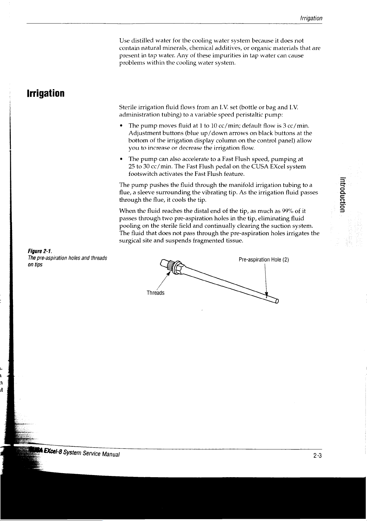
Figure
The
pre-aspiration
on
tips
2-1.
holes
and
threads
Sterile
administration
e
e
The
flue, a sleeve
through
When
passes
pooling
The
surgical
irrigation
The
pump
Adjustment
bottom
you
The
25
footswitch
to
pump
to
30
pump
the
the
through
on
fluid
site
of
the
increase
cc/min.
pushes
surrounding
flue,
fluid
the
that
and
moves
can
activates
does
fluid
flows
tubing)
buttons
reaches
two
sterile
to a variable
fluid
(blue
irrigation
or
decrease
also
accelerate
The
Fast
the
the
fluid
it
cools
the
the
pre-aspiration
field
not
pass
suspends
from
an
speed
at 1 to
10
cc/min;
up/down
display
Fast
through
the
distal
and
through
fragmented
column
the
irrigation
to a Fast
Flush
pedal
Flush
the
vibrating
tip.
end
holes
continually
LV.
set
(bottle
peristaltic
default
arrows
feature.
manifold
tip.
of
the
in
the
pre-aspiration
tissue.
on
on
the
flow.
Flush
on
the
As
the
tip,
as
the
tip,
clearing
Pre-aspiration
or
bag
pump:
flow
black
buttons
control
speed,
CUSA
pumping
Excel
irrigation
irrigation
much
as
eliminating
the
suction
holes
Hole
and
1.V.
is 3 cc/min.
at
panel)
allow
at
system
tubing
fluid
passes
99%
of
it
fluid
system.
irrigates
(2)
the
to
a
lOH9nDOJUI
the
Threads
Page 25
Aspiration
(Suction)
Aspiration
(Suction)
A
vacuum
maximum
arrows
the
control
100%
The
pump,
through
materials
canister.
through a contamination
matter
A
suction
on
and
e
When
+
When
e
In
pinch
*
In
stoppage
pump
vacuum
on
black
panel)
in
10%
suction,
pulls
the
distal
pass
From
or
moisture,
pinch
closes
priming
pressing
Run
Status,
valve
Lap
Mode,
in
the
at
sea
buttons
allow
increments.
which
produces
irrigation
through
the
valve
to
closes
prevents
end
suction
preventing
on
stop
suction
the
irrigation
the
when
for
when
depletion
fluid,
of
the
Fast
you
console
level.
at
the
bottom
you
to
an
fragmented
the
surgical
manifold
canister,
guard
the
front
in
Flush
you
release
about
release
body
provides
Adjustment
of
the
increase
air
that
them
the
system
one
of
or
stream
tissue,
tip.
suction
the
air
filters
from
of
the
console
following
pedal
the
Vibration
second,
the
Vibration
the
pneumoperitoneum.
up
buttons
aspiration
decrease
moving
and
From
the
tubing
stream
any
remaining
entering
opens
cases:
then
to
660
mm
(green
display
the
suction
toward
other
tip,
the
into
the
continues
the
vacuum
when
pedal.
re-opens.
pedal.
In
This
mercury
up/down
column
from
10
the
vacuum
materials
aspirated
suction
to
flow
particulate
pump.
the
system
this
case,
the
suction
on
to
is
To
avoid
valve.
When
the
suction
suction
injury
the
pinch
to
System
pinch
valve
surgical
Power
valve
allows
personnel,
Switch
remains
is
closed. A button
you
to
keep
off,
open
fingers
the
suction
the
valve
away
from
pump
on
manually.
the
the
suction
remains
front
of
pinch
off
the
and
24
EXcel-8
CUSA
System
Service
Mam”
Page 26
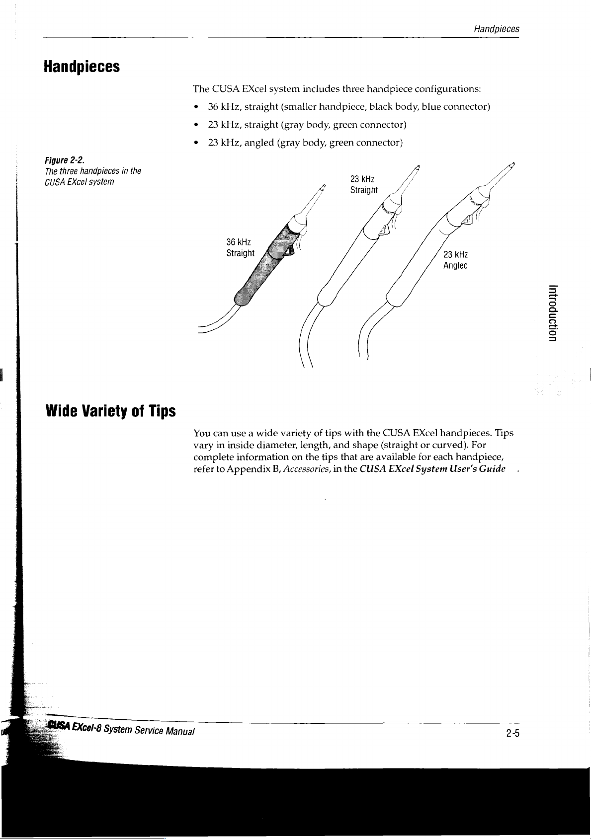
Handpieces
Figure
2-2.
handpieces
three
The
system
EXcel
CUSA
in
the
The
CUSA
e
36
e
23
。
23
EXcel
kHz,
straight
kHz,
straight
kHz,
angled
36
kHz
Straight
system
(smaller
(gray
(gray
includes
handpiece,
body,
green
body,
green
three
handpiece
black
connector)
connector)
kHz
23
Straight
configurations:
body,
blue
connector)
и
Handpieces
^
Wide
Variety
of
Tips
You
can
vary
in
inside
complete
refer
to
Appendix
use a wide
diameter,
information
B,
variety
Accessories,
of
length,
on
the
tips
and
tips
in
with
shape
that
the
the
CUSA
(straight
are
available
CUSA
EXcel
EXcel
or
curved).
for
each
System
handpieces.
For
handpiece,
User's
Guide
UOH9nDOJiUI
Tips
EXcel-8
System
Service
Manual
>
Page 27
Unpacking
and
Installing
the
The
CUSA
Responsibility
EXcel
of
System
In
this
section:
e
The
responsibility
e
Unpacking
¢
Preparing
4
4
4
4
the
Manufacturer
the
the
Replacing
Replacing
Replacing a Control
Installing
of
CUSA
CUSA
the
power
fuses
the
reference
the
manufacturer
EXcel
system
EXcel
console
connector
(if
necessary)
Panel
card
for
use:
overlay
(optional)
set.
LUSA
EXcel-
8
System
Service
Manual
Valleylab
CUSA
EXcel
*
The
person
and
setup
+
Authorized
modifications,
*
The
electrical
codes
*
You
use
for
use.
For
warranty
is
responsible
system
unpacking
procedures
persons
or
installation
and
regulatory
the
equipment
information,
for
the
only
under
and
in
this
perform
repairs.
of
requirements.
in
accordance
refer
safety,
reliability,
the
following
installing
manual.
assembly
the
to
the
relevant
with
the
Preface
and
performance
circumstances:
unit
follows
operations,
room
complies
the
Valleylab
section
of
of
the
the
installation
re-adjustments,
with
local
instructions
this
manual.
3-1
Page 28
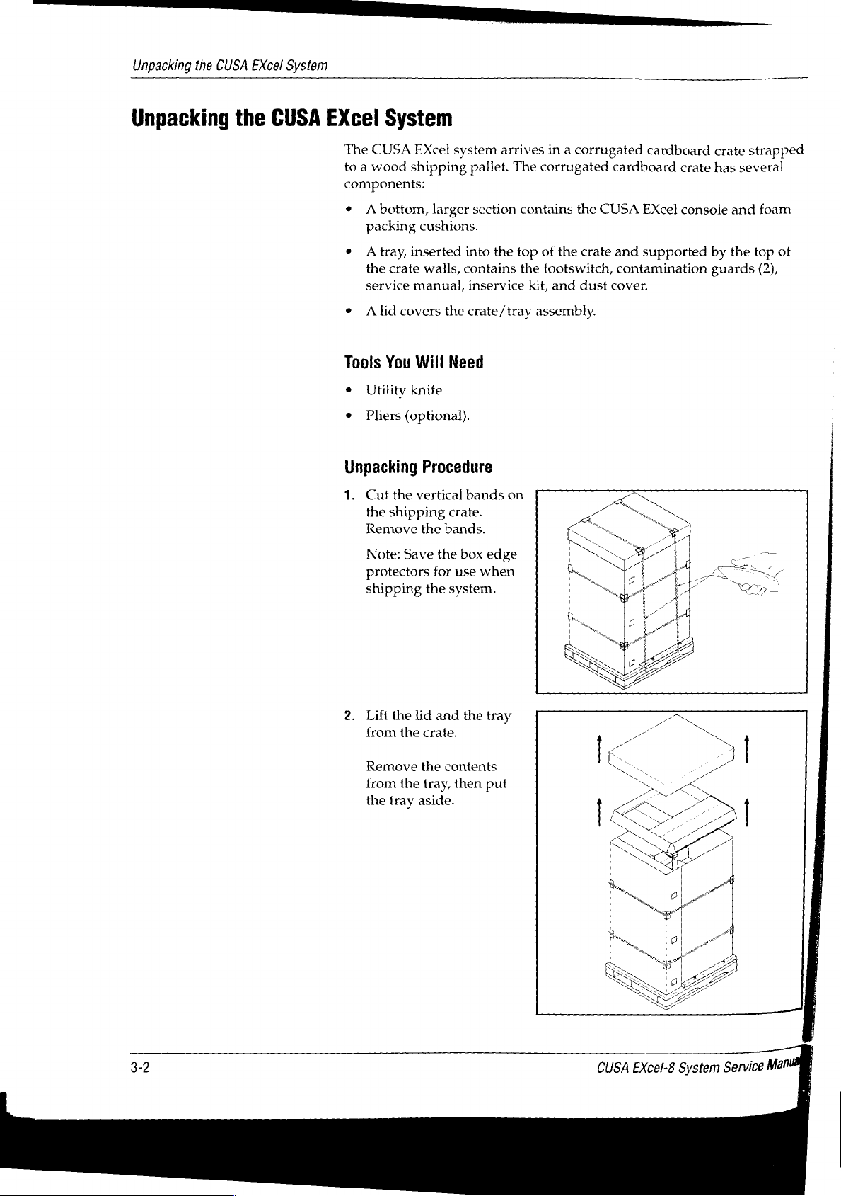
Unpacking
the
CUSA
EXcel
System
Unpacking
the
CUSA
EXcel
The
CUSA
to a wood
components:
*
Abottom,
packing
+ A tray,
the
service
e
Alid
Tools
e
Utility
+
Pliers
Unpacking
1.
Cut
the
Remove
System
EXcel
shipping
larger
cushions.
inserted
crate
walls,
manual,
covers
You
the
shipping
the
Will
knife
(optional).
Procedure
vertical
the
bands.
system
pallet.
section
into
the
contains
inservice
crate/tray
Need
bands
crate.
arrives
The
corrugated
contains
top
of
the
footswitch,
kit,
assembly.
on
in a corrugated
cardboard
the
CUSA
the
crate
and
contamination
and
dust
cover.
cardboard
crate
EXcel
console
supported
crate
has
several
and
by
the
guards
strapped
foam
top
of
(2),
Note:
protectors
shipping
2.
Lift
from
Remove
from
the
tray
Save
the
the
the
the
for
the
system.
lid
and
crate.
the
contents
tray,
aside.
box
use
the
then
edge
when
tray
put
一
3-2
EXcel-8
CUSA
System
Service
Man
Page 29
Unpacking
the
CUSA
EXcel
System
|
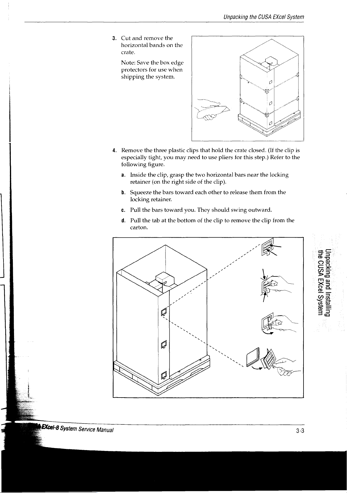
3.
Cut
horizontal
crate.
Note:
protectors
shipping
4.
Remove
especially
following
a.
Inside
retainer
b.
Squeeze
locking
c.
Pull
and
Save
remove
bands
the
for
use
the
system.
the
three
tight,
figure.
the
clip,
(on
the
retainer.
the
bars
the
on
box
edge
when
plastic
you
grasp
the
right
bars
toward
the
clips
that
may
need
to
the
two
horizontal
side
of
the
toward
each
you.
They should
hold
use
pliers
clip).
other
the
crate
for
bars
to
release
swing
closed.
this
step.)
near
the
them
outward.
(If
the
Refer
locking
from
clip
the
to
is
the
d.
Pull
the
carton.
tab
at
the
bottom
of
the
clip
to
remove
the
clip
from
the
SU)
VSNO
Bupjoedur)
pue
[99XI
UIBISÁS
Gurexsu]
Page 30
Unpacking
the
CUSA
EXcel
System
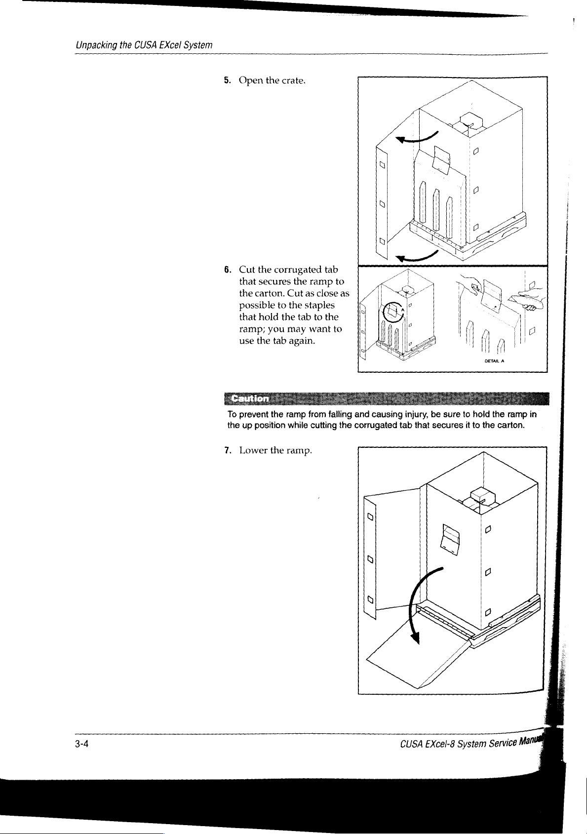
5.
Open
6.
Cut
that
the
possible
that
ramp;
use
the
crate.
the
corrugated
secures
carton.
the
hold
you
tab
Cut
to
the
may
the
ramp
as
the
staples
tab
to
want
again.
tab
to
close
the
to
as
To
the
7.
prevent
up
position
Lower
the
the
ramp
from
while
ramp.
falling
cutting
and
causing
the
corrugated
injury,
tab
that
be
sure
secures
to
it
hold
to
the
the
ramp
carton.
in
CUSA
EXcel-8
System
Mani
Service
Page 31

Unpacking
the
CUSA
EXcel
System
8.
9.
Lift
the
walls
off
Remove
around
Remove
corrugated
the
pallet.
the
four
interlocking
the
console
the
right
and
carton
(refer
left
foam
to
the
following
foam
cushions
pieces
from
from
the
figure).
the
console.
foam
cushion
À
EXcel-8
System
Service
Manual
9
VSNI
Gumoedun
pue
[99XI
LUB]SÁS
furesu]
Page 32

Unpacking
the
CUSA
EXcel
System
10.
Cut
the
remove
console.
the
vertical
clear
the
band
plastic
bag
bag,
from
on
then
the
11.
The
rear
one
direction;
prevent
a.
Unlock
b.
Check
console
casters
the
the
wheels
the
front
the
rear
to
roll
have
front
from
casters
casters
toward
direction
casters
have
rolling
by
lifting
to
be
the
ramp.
locks
brake
(vefer
sure
that
to
the
that,
keep
locks
the
following
lock
lever
if
locked,
the
that,
wheels
when
figure).
upward.
they
will
rolling
in
locked,
allow
the
CUSA
EXcel-8
System
Mani
Service
Page 33

Unpacking
the
CUSA
EXcel
System
12.
Roll
ramp.
are
you
console
of
13.
Unlock
release
the
cushion
control
the
console
If
the
unlocked,
do
not
to
the
ramp.
the
tab,
U-shaped
from
panel.
down
rear
be
allow
roll
off
control
then
foam
under
the
casters
sure
that
the
the
side
arm
remove
the
.
a
;
|
>
7
-i
Put
the
box
plastic
if
that
ship
packing
the
information
Policy,
Inspect
If
repair
arrange
If
Valleylab
bag
you
need
you
the
console.
procedures
console,
in
all
any
damage
or
repair
you
have
for
use
this
contents
replacement
Service
edge
protectors
storage.
to
return
the
proper
If,
you
may
on
packing
guide.
has
occurred,
or
replacement,
any
questions
Center
and
Save
all
the
console
materials
in
Valleylab's
or
if
you
void
the
the
console
for
damage
notify
of
damaged
about
nearest
all
foam
shipping
to
Valleylab.
and
judgement,
use
improper
warranty
for
:
that
may
Valleylab
parts.
refer
to
the
contents
you,
packing
components.
In
the
proper
you
packaging
on
this
shipping,
have
immediately
For
more
Section
of
or
your
Valleylab
materials
You
fact,
it
packing
fail
to
materials
system.
refer
to
occurred
information
13,
Repair
these
cartons,
into the
will
is
very
procedures
use
the
For
more
Section
during
to
Policy.
representative.
clear
need
them
important
proper
to
return
13,
Repair
shipping.
arrange
on
how
contact
to
to
the
041
YSNO
Buryoedun
pue
|99X
91SAS
Guyjesu]
Cel-8
System
Service
Manual
Page 34

Preparing
the
CUSA
EXcel
Console
for
Use
Preparing
the
CUSA
EXcel
Valleylab
contains
*
Console
ο
Footswitch
e
In-service
*
Contamination
e
Service
e
Dust
The
small
e
User's
e
Reference
e
Instructions
panel
+
Tip
On
the
e
Common
Console
ships
the
the
following
kit
manual
cover.
box
contains
guides
card
for
card.
CUSA
Excel
European
for
Use
CUSA
guard
set
EXcel
items:
several
installing
console,
power
system
other
items:
reference
Valleylab
connector
in
two
boxes.
card
set
provides
in
the
the
following
The
large
console
box
control
items:
e
220
to
240V,
e
International
Before
set.
If
power,
If
international
your
+
Replace
e
Change
your
shipping,
facility
you
need
the
the
facility
control
T5A,
time
delay
(symbols
Valleylab
uses a different
to
make
power
fuses.
has
ordered
only)
includes,
power
the
appropriate
connector.
an
English
panel overlay
fuses
control
but
connector
language
and
panel
overlay ~ installed.
does
not
install, a reference
or
receives
changes
reference
to
kit,
replace
card
the
system:
set.
95
the
to
120
card
V
3-8
EXcel-8
CUSA
System
Service
Ma
Page 35

Preparing
the
CUSA
EXcel
Console
for
Use
Table
3-1.
Wire
colors
D
important
Ensure
comply
regulatory
that
all
electrical
with
local
codes
requirements.
installations
and
Replacing
If
your
connector
connector
Tools
Slotted
Procedure:
1.
Remove
2.
Attach
Wire
green
brown
light
The
power
defeat
adapters.
connectors.
to
remove
the
facility’s
supplied
according
needed:
blade
the
the
Color
with
yellow
blue
connector
its
purpose
Periodically
Always
the
Power
power
screwdriver
connector
new
stripe
Connector
receptacles
on
the
to
your
connector,
meets
by
using
check
grasp
connector
are
CUSA
provided
cords
from
EXcel
institution’s
using
all
requirements
extension
the
power
by
the
wall
not
compatible
system,
policy.
with
the
the
following
Prong
safety
ground
line/hot
neutral
cords
cord
the
connector;
receptacle.
with
the
standard
install a different
unit.
chart:
for
safe
grounding.
or
three-prong-to-two-prong
for
damaged
do not
insulation
pull
on
power
Do
the
not
or
cord
If
required
to
the
equipotential
by
local
regulations,
grounding
connect
lug
on
an
equipotential
the
rear
of
the
grounding
CUSA
EXcel
cable
console.
SU
YSNO
Bupjoedun
pue
199XI
UslSAS
Guyasu
EXcel-8
System
Service
Manual
の
Page 36

Preparing
the
CUSA
EXcel
Console
for
Use
Figure
3-1.
Replacing
fuses
Replacing
Notice
To
avoid
product
power
supply:
»
220
to
240 V —
«
95
to
120
V —
You
must
change
following
‧
<A
*
Your
Tools
Procedure
1.
Using
45°).
situations
fuse
burns
facility
needed:
the
The
230V = 5A
115V = 10A
(refer
Fuses
(If
Necessary)
damage,
T5A,
Time
T10A,
Time
the
fuses
occur:
out.
receives
Small
flat-headed
to
Figure
screwdriver,
fuse
holder
be
sure
Delay
Delay
(located
95
to
120 V power.
3-2):
turn
pops
loose.
to
insert
fuses
(default)
on
the
screwdriver
the
fuse
cover
that
are
appropriate
rear
panel)
counterclockwise
if
either
to
the
of
the
(about
Fabie
3-2.
3-10
Fuse
values
2.
Remove
3.
Replace
Volts
220
to
240
95
to
120
4.
Insert
the
V
V
the
the
fuse
fuse:
holder,
holder
Amps
T5A
T10A
and
turn
from
the
the
fuse
rear
cover
CUSA
panel.
clockwise.
EXcel-8
Type
Time
Delay
Time
Delay
System
(default)
Service
Mar
4
È
Page 37

Preparing
the
CUSA
EXcel
Console
for
Use
D
Important
When
care
not
assembly
head.
the
screws
to
fall
=
let
out
are
the
control
of
loose,
panel
the
control
take
Replacing a Control
On
the
control
shipments
overlay
Valleylab
overlay
symbols.
person
replace
Tools
+
*
Remove
1.
2.
3.
who
the
needed:
Small
Phillips
Swivel
the
front
Remove
at
the
the
control
Slide
following
4
40
panel,
outside
on
which
also
makes
showing
If
your
unpacks
international
pliers
screwdriver.
the
Control
the
control
of
the
four
rear
of
head.
the
control
cables:
pin
ribbon
Panel
an
the
United
symbols
an
English
facility
the
Panel
head
console.
screws
the
control
panel
cable
Overlay
overlay
States,
identify
English
language
has
purchased
CUSA
overlay
Assembly
so
that
(M4
Phillips)
head,
forward
(j3)
(Optional)
identifies
Valleylab
the
control
language
words
the
EXcel
system
with
the
the
front
and
that
fasten
far
enough
buttons
provides
panel
kit
available
rather
than
English
and
English
of
the
four
lock
the
control
to
and
indicators.
an
features.
part
international
language
prepares
language
control
allow
panel
washers
panel
disconnecting
For
international
However,
of
which
is
an
kit,
the
it
for
use
must
overlay.
is
90°
from
(M4),
located
assembly
to
the
3-2.
Figure
一
Disconnecting
cables
—
control
panel
assembly
4
4
4
20
pin
10
pin
6pin
ribbon
cable
cable
cable
(J4)
(J2).
(15)
gc
©
3
os
se
©
Pa
Es
x5
oo
La
42
D
=
38
E
_
USA
A
2.
EXcel-8
System
Service
Manual
4.
Remove
the
control
panel
assembly
from
the
control
head.
3-11
Page 38

Preparing
the
CUSA
EXcel
Console
for
Use
Figure
3-3.
Removing
the
control
panel
overlay
Remove
Four
snap-in
1.
Attach
2.
With
on
3.
With
assembly
the
Control
an
your
the
standoffs
the
Panel
standoffs
ESD
strap.
fingertips
to
flanges
to
retracted,
release
Overlay
fasten
or
small
retract
the
overlay.
them.
the
overlay
pliers,
push
to
squeeze
the
standoffs
the
control
the
panel
spring-loaded
out
of
the
assembly.
flanges
control
panel
CUSA
EXcel-8
System
Mam
Service
Page 39

Install
the
Control
Panel
Assembly
Preparing
the
CUSA
EXcel
Console
for
Use
|
>
important
While
care
assembly
head.
the
not
to
YO
screws
let
the
fall
out
are
still
loose,
control
panel
of
the
control
take
1.
Remove
Notice
To
avoid
to
the
Machine
2.
Position
3.
Before
connect
4
40
4
20
4
4
6
4.
Slide
5.
Replace
at
the
the
6.
Swivel
with
Install
the
ESD
product
the
sliding
the
pin
pin
10
pin
pin
cable
the
control
four
rear
control
the
the
front
Control
strap.
damage,
Control
control
the
following
ribbon
ribbon
cable
(J4)
(J2).
screws
of
the
control
head.
control
of
Panel
remove
PCB.
panel
control
cables (Refer
cable
(J3)
cable
(J5)
panel
assembly
(M4
head
the
console.
Overlay
the
assembly
panel
Phillips)
head,
that
so
that the
ESD
wrist
at
the
assembly
to
Figure
into
the
and
four
fasten
front
strap
before
control
into
the
3-2):
control
lock
the
control
of
the
control
connecting
head
control
head.
washers
panel
opening.
head,
(M4),
assembly
panel
aligns
cables
located
to
Refer
1.
Identify
Remove
Position
When
от
control
and
5.
Plug
6.
Turn
to
Figure
hear
the
on
the
the
it
correctly
the
tips
panel,
them
power
the
3-5.
overlay
protective
AC
of
the
push
snap
cord
Main
to
on
standoffs
on
into
connector
Switch, located
be
used.
tape
from
the
control
the
standoffs
place.
the
rest
into
overlay
panel.
in
the
corresponding
with
your
the
wall
on
the rear
edges.
holes
thumbs
receptacle.
until
panel.
in
you
the
feel
9
VSNI
6ul)oedun
pue
[90X3
ul91SAS
6ulllelsul
EXcel-8
System
Service
Manual
Page 40

Preparing
the
CUSA
EXcel
Console
for
Use
Figure
3-4.
installing
the
control
panel
overlay
3-14
CUSA
EXcel-8
System
Man
Service
Page 41

Preparing
the
CUSA
EXcel
Console
for
Use
Figure
3-5.
installing
the
reference
cards
Installing
You
Refer
need
to
the
to
Figure
Reference
install
the
3-6
for
Card
Set
reference
instructions.
card
set
into the
rear
of
the
control
panel.
σσ]
9M1
YSND
Surjoeduy
pue
[89X
SÁS
6ullelSul
LUG]
id
EXcel-8
System
Service
Manual
n°
Page 42

Console
Components
In
this
section:
e
Console
*
Control
e
Console
+
Console
*
Console
+
Symbols
overview
panel
body
front
body
side
body
rear
on
the
and
structural
panel
panel
panel
control
features
panel
‘ant
For
Your
EXcel-8
Information
System
Service
Manual
e
Other
features.
This
section
of
the
console,
components.
the
function
presents
then
describes
The
description
each
subsystem
the
CUSA
EXcel
each
major
includes
or
component
console.
an
It
console
illustration
serves.
begins
with
subsystem
and a brief
an
overview
and
its
sketch
of
全
Page 43

Console
Console
Figure
Console
Overview
4-1.
structural
and
Structural
Overview
features
Features
and
Structural
This
structural
drawing
features
Features
presents
the
called
front
out.
view
of
the
|
CUSA
Control
LV.
EXcel
panel
pole
console,
with
Console
body
(
TT
ZS
У
==
>
A
5
L
SN
=
cusa
EX
№
Housing
pump
suction
Arm housing
+
=
Cooling water
reservoir
Shelf
canister
head
pinch
for
for
suction
irrigation
and
valve
4-2
CUSA
Casters
EXcel-8
System
Service
Page 44

I.V.
Pole
Console
Overview
and
Structural
Features
]
Attached
fluid
pole
Control
Mounted
system
Arm
e
e
e
The
panel.
Housing
to
the
container.
90°
in
the
Panel
on
the
functions.
and
Arm
Supports
Allows
panel
Adjustable—lifts
generator
Arm
the
the
from
to
Housing
for
Irrigation
right
side
You
can
lower
position.
arm,
the
The
next
Housing
control
control
most
sit
on
covers
panel
of
the
to
allow a CUSA
top
of
the
raise
or
control
page
panel.
to
operating
of
the
the
arm
Pump
console,
lower
the
panel
presents
pivot
135°
room.
Electrosurgical
console
attachment
Head
and
it
supports
pole;
allows
control
to
allow
body,
Suction
you
the
user
panel
users
under
along
the sterile
can
also
rotate
to
contro]
details.
to
see the
Module
the
control
the
console
Pinch
Valve
irrigation
the
ail
control
(CEM)
panel.
body
side
The
prominent
following
*
The
irrigation
blue
lines)
*
The
suction
light
green
Console
The
other
Shelf
The
Body
main
working
for
shelf
provides a place
Casters
Unlocked,
¢
Front
casters
e
Rear
casters
one
direction.
black
area
features:
pump
head
pinch
valve
line).
body
of
the
console
components. A later
Suction
both
Canister
front
and
have
have
direction
rear
brake
at
the
and
to
locks
put
top
of
and
irrigation
suction
unit
contains
page
the
casters
that
locks;
the
console
tube
tube
pathway
the
presents
hospital
roll
easily
stop
the
when
locked,
body
includes
pathway
(marked
electronics,
console
provided
and
wheels
suction
rotate
from
casters
(marked
with
pumps,
body
details.
canister.
freely.
rolling.
remain
the
with
and
fixed
a
ajosuos
in
pe
EXcel-8
System
Service
Manual
sjuguodulos
Page 45

Control
Panel
Control
Figure
4-2.
Control
panel
Lap
Mode
prio
(Rea)
Fo
nis
witeh
Handpiece
Cooling
Water
^
Panel
features
Lap
On
button
|
N
jo
Apos
= | |
SI
tool
=
|
Ez!
Ae.
indicator
=
m
400
TT
=
80
9
60
A
slot
in
the
reference
Prime
button
\
=>
ka
CT]
SE
し
ls
NN
Г
1
|
는
rear
guide.
6
of
the
Test
control
button
\
=
=
Tlm
TITS
“lg
し
|
|
[
| に ニニ
ls
panel
allows
Status
Indicators:
Run
(Green)
Standby
Wait/Cooling
(Amber)
Гог]
|
70
60
you
to
store
Water
(Amber)
Status button
=
=]
o.
DI
7
Co
ao
i
the
|
W
ts
quick
|
|
|
N
Displays
(Green
and values)
4-4
9
pid
|
し
LED
columns
40
|
30
|
10%
r
A
Ww
|
1
| し _
に
|
hd
a
e
4
‘
3
тот
É
и
|
|
|)
a
40
Lo
二
30
ol
10%
y
|
| |
CUSA
I
—
|
し
|
TISSUE
Select”
a
y
QN
EXcel-8
tit
++
=
se
System
Service
Page 46

Control
Panel
Alerts
All
alerts
are
red.
When
lit,
the
alerts
indicate
the
following:
[F
N
个
y
O
Alert:
An
alert
Vibration:
Footswitch:
panel.
Handpiece:
Cooling
Lap
To
deactivate
button
Lap
provides
pedal.
When
indicator
Amplitude
Connector
Connector
Water:
Mode,
activate
once;
Mode:
Selects
no
you
light.
Lap
the
activate
condition
Cooling
Prime,
Mode,
function,
it
automatically
the
suction
exists.
is
out
not
not
water
Test,
Prime,
Laparoscopic
to
the
the
Lap
of
range.
plugged
plugged
problem
and
or
press
the
deactivates
handpiece
Mode,
into
its
into
its
in
Status
Status,
button
mode
until
the
system
receptacle
receptacle
the
system.
Buttons
press
the
button
again.
To
when
the
of
operation—the
you
activate
turns
on
the
console
on
the
console.
once;
activate
test
on
Test,
is
complete.
system
the
the
Lap
rear
to
press
Vibration
On
the
Prime:
Automatically
irrigation
minute.
Test:
increasing
4
seconds.
Status:
fluid
Verifies
tip
Toggles
Displays
Green
light
Aspiration,
*
Not
Activated:
。
Activated:
For
TISSUE
the
highest
setpoint
increases
to
the
tip. A timer
the
handpiece
amplitude
the
status
emitting
Irrigation,
Select,
All
diodes
and
One
LEDs
“Std”
value.
irrigation
is
working
to
100%,
between
(LEDs)
Amplitude:
LED
illuminates
up
to
and
(standard)
rate
turns
Prime
properly
then
decreasing
Standby
show
user
to
including
is
the
first
to
off
and
Run.
adjusted
show
the
setpoint
25
to
30
cc/min
after
approximately
by
automatically
it
to
0%—all
setpoints
the
setpoint
setpoint
value
value;
to
within
for
value
light
“++++”
pump
one
up.
is
90503
EXcel-8
System
Service
Manual
S1uauodu109
Page 47

Control
Figure
4-3.
Contro!
Panel
panel
features
(continued)
Status
indicators:
Run
(Green)
Standby
Wait/Cooling
(Amber)
Water
(Amber)
全 一 一 一 一
© ©
一
|
10%
a4
050
a
N 0
1ccmin
1
J
|
|
10%
TÍ
|
U
TISSUE
|
St
Select”
№
Setpoint
(Up/Down
Aspiration
Irrigation
Amplitude
TISSUE
adjustment
arrows):
(Green)
(Blue}
(Orange)
Select
buttons
(Yellow)
CUSA
EXcel-8
System
Ma
Service
Page 48

Control
Panel
Status
To
button.
Run: A green
Standby:
status.
Wait:
+
*
e
e
Cooling
¢
*
Indicators
change
Flashing - Immediately
the
Flashing — Immediately
Switch,
Continuous — When
Continuous — When
Immediately
system
Immediately
system
from
An
amber
An
amber
system
the
Water:
automatically
automatically
Standby
LED
illuminates
LED
LED
automatically
system
An
amber
after
after
to
Run,
to
show
illuminates
illuminates
automatically
any
in
LED
turning
fills
turning
drains
in
after
turning
fills
after
alarm
Prime
illuminates
on
the
off ( © ) the
handpiece
or
from
Run
when
to
show
the
following
on ( | ) the
the
handpiece
turning
mode.
(| ) the
handpiece
off ( () ) the
drains
condition
in
System
to
Standby,
the
system
when
the
circumstances:
with
handpiece
exists
the
following
Power
with
cooling
System
cooling
Power
water.
press
is
in
Run
system
System
cooling
System
is
Power
water
Power
cooling
circumstances:
Switch,
water.
Switch,
the
Status
status.
in
Standby
Switch,
water
the
the
Setpoint
Marked
setpoint
Aspiration
100%.
Irrigation:
3
cc/min.
Amplitude:
TISSUE
TISSUE
Setting
Std
+
++
+++
十 十 十
*}
ms = 1
Push a button
the
additional
Adjustment
with
values:
(Suction):
10
increments;
10
increments;
Select: 5 increments
Select
十
millisecond = 1
button
changes a setpoint
setpoint
Buttons
Up/Down
10
increments;
interrupts
one-thousandth
once
for a single
value
arrows,
linear
linear
scale
linear
scale
from
std
continuous
On-Time
continuous
40
ms
30
ms
20
ms
10
ms
change
value
changes
these
buttons
scale
of 1 to
of
10
(standard
vibration
of a second
in
by
only
by
holding
allow
of
10
to
10
cc/min;
to
100%;
operation)
for
setpoint
one
setting
down
you
to
100%;
default
default
default
specified
Off-Time
0
10
10
10
10
value.
to
ms”
ms
ms
ms
ms
(you
the
button).
value
++++.
Holding
adjust
value
is
times:
get
no
the
value
is
10%.
down
is
9I0SU09
SJU9U0dUJ0
and
*
EXCel-8
System
Service
Manual
tI
Page 49

Console
Body
Front
Panel
Console
Figure
4-4.
Console
body—front
Body
view
Handpiece
connector
receptacle
Front
Panel
Irrigation
pump
head
Handpiece
This
the
Connector
receptacle
left
side
(as
ーーーーー
allows
you
つ
Receptacle
you
to
face
the
È
Г]
``
OK
|
connect
front
the
panel)
of
Contamination
Retaining
suction
handpiece
the
console.
bail
canister
to
the
guard
for
console.
It
is A |
4-8
EXcel-8
CUSA
System
Service
Ma
Page 50

Console
Body
Front
Panel
Suction
To
valve.
When
*
*
+
*
The
System
pinch
button
manually.
System
Turning
filling
activates
water
deactivates
Pinch
avoid
injury
closed,
When
priming
When
pressing
In
Run
Status,
pinch
valve
In
Lap
Mode,
stoppage
suction
has
valve
on
the
Power
this
the
handpiece
the
from
Valve
to
surgical
the
valve
when
closes
when
prevents
pinch
valve
been
running,
remains
front
Switch
switch
cooling
the
cooling
all
system
personnel,
pinches
the
irrigation
the
Fast
you
for
about
you
depletion
default
when
open
until
of
the
suction
on ( | ) activates
with
cooling
water
drain
water
components.
keep
off
system
Flush
pedal
release
one
release
of
position
you
the
pinch
cycle.
system
water.
fingers
away
suction
the
second,
the
the
tum
drain
flow
to
Vibration
Vibration
pneumoperitoneum.
(system
the
cycle
valve
all
system
Turning
When
(about
pedal.
then
re-opens.
pedal.
off)
Power
has
allows
components
this
the
system
one
minute),
from
the
suction pinch
the
handpiece:
In
this
case,
This
suction
is
closed.
Switch
finished, then
you
switch
If
off,
the
to
open
and
off ( ©
has
drained
it
automatically
the
the
suction
closes.
the
valve
begins
)
A
on
etmemem
»
Important
The
guard
becomes
ο,
CAREERS
is
hydrophilic
when
blocked
AIRE
PONS
AECA
and
wet.
Irrigation
A
latch
right
peristaltic
the
peristaltic
Contamination
Protects
suction
months
six
rotates
to
close.
pump.
the
stream.
Pump
from
When
pump.
vacuum
It
when
or
Head
right
open,
Closed,
Guard
pump
necessary
is
becomes
it
to
left
it
allows
the
from
to
open
you
pump
head
particulate
replace
to
blocked.
the
pump
to
place
irrigation
holds
irrigation
matter
contamination
the
head,
and
and from
tubing
tubing
moisture
guard
left
to
into
the
against
in
the
every
S
D
Retaining
bail
The
Bail
holds
for
suction
the
Suction
Canister
canister
in
place
on
the
shelf.
|
ーー
CUSA
Excer-g
O
System
Service
Manual
4-9
=
S
E
5
©
=
の
Page 51
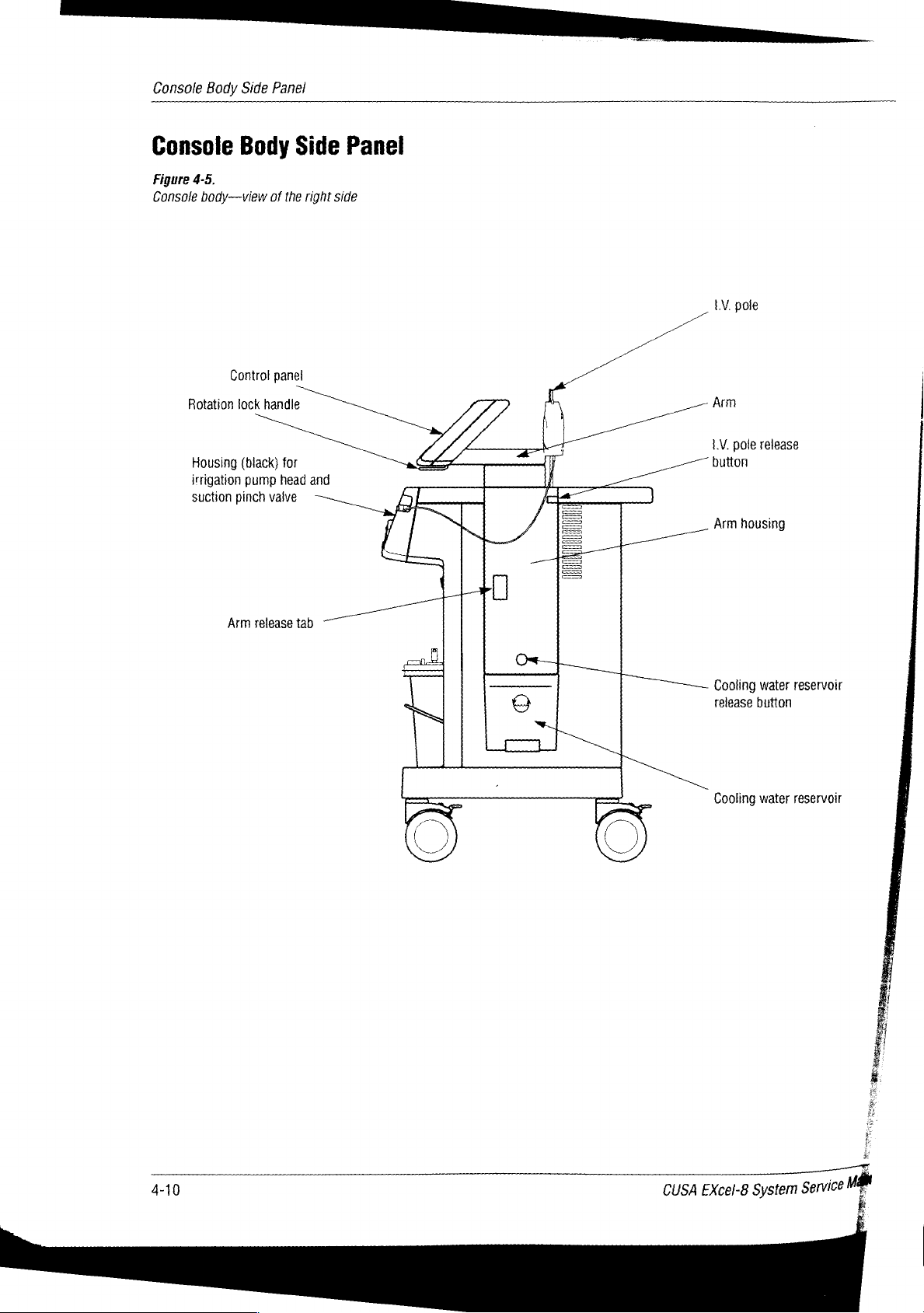
Console
Body
Side
Panel
Console
Figure
4-5,
Console
body—view
Control
Rotation
Housing
irrigation
suction
Body
tock
(black)
pump
pinch
of
the
panel
handle
for
head
valve
Side
Panel
right
side
and
A
[
ilin
LV.
pole
Arm
3
N
т
Em
v..
=
=
P
|
]
一
LV.
button
Arm
一
pole
release
housin
°
Arm
release
tab
一
一
一
©
I
—
Cooling
water
release
button
reservoir
4-10
M
CUSA
EXcel-8
System
Service
dh
Page 52

Console
Body
Side
Panel
Control
Refer
Panel
to
pages
Rotation
This
handle
one
of
four
e
Straight
e
45º
right
ο.
45°
left
e
90°
left.
Housing
Refer
I.V.
Refer
to
pages
Pole
to
pages
for
4-4
through
Lock
Handle
releases
positions:
forward
Irrigation
4-2
and
4-2
and
the
4-3.
4-3.
4-7.
control
Pump
Head
panel,
and
allowing
Suction
it
to
swivel
Pinch
and
lock
Valve
into
I.V.
Pole
Release
This
button
Arm
Refer
and
to
pages
releases
Arm
Arm Release
This
tab
releases a lock
Cooling
This
the
A
dlear
water
The
Arm
automatically
Water
container
handpiece.
panel,
level
inside
reservoir
Housing
also
Button
the
Housing
4-2
and
Tab
Reservoir
holds
cooling
The
reservoir
which
runs
the
reservoir.
includes
on
the
console
connect
the
I.V.
pole,
4-3.
that
holds
water
holds
vertically
fittings
side
reservoir
allowing
the
arm
to
be
continuously
1000
cc
up
the
that
snap
panel.
The
to
the
you
to
in
three
of
distilled
side,
allows
into
fittings
cooling
raise
it
or
lower
vertical
receptacles
water
positions.
circulated
water.
you
to
see
inside
and receptacles
system.
it.
through
the
the
9|0SU09
*
EXcel-8
System
Service
SlUu9uoduuo9
Manual
"M
Page 53

Console
Body
Rear
Panel
Console
Figure
4-6.
Console—rear
Body
view
Rear
Panel
|
=
Speaker
Volume
и
Footswitch
receptacle
control
connector
ne
I
И
AC
main
Fuses
Footswitch
switch
(2)
4-12
CUSA
EXcel-8
System
Mam
Service
Page 54

=)
Speaker
The
speaker
when
vibration
Volume
This
potentiometer
You
cannot
Footswitch
This
receptacle
AC
Main
This
switch
does
not
wall
receptacle
Once
the
unplug
sounds
Control
adjust
Connector
Switch
controls
activate
AC
Main
the
system
an
is
active.
allows
the
allows
the
the
system;
to
the
Switch
from
audible
alert
you
to
tone.
tone
Receptacle
you
to
connect
flow
of
AC power
instead,
System
is
the
Power
On ( |
wall
when
an
adjust
the
active
the
footswitch
to
it
allows
Switch.
),
you
can
receptacle.
alert
the
CUSA
power
leave
Console
condition
vibration
it
to
to
On
Body
the
console.
EXcel
flow
even
Rear
exists
and
audible
system.
from
the
when
Panel
tone.
It
you
Fuses
These
protect
Replacement
Footswitch
The
footswitch
functions:
*
Ultrasonics/vibration:
vibration
*
Fast
to
25
suction.
value
the
Procedures
at
Flush:
to
30
cc/min.
When
and
suction
system
has
the
Left
you
two
tip.
pedal
from
electrical
for
instructions
pedals
Right
When
you
(blue),
It
also
closes
release
resumes.
the
overloads.
on
in a base,
pedal
(orange),
release
when
pressed,
the
Suction
pedal,
irrigation
replacing
and
allows
when
the
pedal,
increases
Pinch
returns
Refer
to
Section
the
fuses.
you
to
pressed,
vibration
the
Valve,
to
11,
activate
stops.
irrigation
stopping
the
two
activates
rate
setpoint
9|0SU09
EXcel-8
System
Service
S1U9U0dUJ0
Manual
me
Page 55

BE
NEN
Console
Figure
Console—rear
Body
4-7.
Storage
Rear
Panel
view
(continued)
compartment
Cord
Serial
number
agency
approval
wraps
label,
model
labels
number,
and
Equipotential
grounding
lug
AC
power
cord
4-14
CUSA
EXcel-8
System
Service
Man
Page 56

AC
Power
Cord
Console
Body
Rear
Panel
Connects
Equipotential
If
you
connect
Label
The
approvals.
Cord
The
two
way.
Storage
This
footswitch
power
are
using a CEM
ground
label
shows
Wraps
unit
has
two
coils
of
cord
Compartment
area,
which
and a manual.
to
Grounding
from
the
on
includes
the
console
cord
the
system
Lug
generator,
the
CEM
serial
wraps.
back
one
These
of
interior
from
the
the
grounding
generator
number,
are
the
unit,
shelf,
wall
receptacle.
to
the
CUSA
model
brackets
keeping
allows
lug
number,
that
the
cords
you
allows
Excel
and
allow
safely
to
store
you
to
console.
agency
you
to
hang
out
a
of
the
9|0SU09
S1U9U0dul09
e.
CUSA
EXcej-g
System
Service
Manual
ms
Page 57

Symbols
on
the
Control
Panel
Symbols
Figure
4-8.
Control
panel
symbols
A
не
S)
>
(77777
o
|
Ls
SOTTO
9
|__|
|
[|
on
the
Control
= a
Lap
©
|
№
|
80
TT
70 Lo
60
gg
4
|
30
」
20
10%
=
Panel
Some
symbols
symbol
Ed
|
|
lo
し
[一
J
PT
|
TIT
|
_
|
|.)
and
its
10
8
7
1
기
6
os
7
4
3
2
1cemin
e
appear
meaning.
on
the
control
=
|
—-
し
—
|
m
に
ーー
デー
|
|
TT]
トー
|)
|
|
oil
=
)
|
デー
|
41%
panel.
№
©
80
70
60
5
40
20
10%
The
following
ーー
ジー
o
|
ro.
|
) |
TE
(pe
OT
し に
し
[|
[+
|
TISSUE
list
a
=
D
Y
ter
**
sm
Select”
shows
|
|
each
a
OF
—Ч=
TI
A
LZ
LÆ
fut
<
να
Vibration:
Alert
(red,
left
Test
(amber,
Footswitch
Handpiece
Cooling
Alert
Wait
water
Suction
irrigation
failure
failure
water:
°
(red,
left
(amber,
through
side
top
side
right
the
of
panel) - amplitude
of
amplitude
or
footswitch
or
handpiece
of
the
control
side
of
the
control
handpiece
out
of
display) — system
not
connected
not
connected
panel)—failure
panel)—system
or
draining
the
handpiece
range
in
Test
mode
is
circulating
cooling
i
|
4-16
CUSA
EXcel-8
System
Service
Ma
Page 58

Symbols
on
the
Control Panel
Amplitude
Standard
Pause/wait
Standby
Ch:
Run
Start
action/change
Prime
Do,
On/selected
adjust
status
Laparoscopic
seo
mode
9I0SU09
CUSA
EXcel-8
System
Service
Manual
S1U9UOdUU0
4-17
Page 59

Other
Features
Other
Features
Reservoir
release
button
The
CUSA
*
Easy-to-fill
*
Adjustable
+
Rotating
*
Adjustable
»
Adjustable
The
next
portion
Filling
To
1.
2.
To
1.
2.
the
remove
Press
reservoir)
Slide
fill
the
Gently
Fill
the
EXcel
console
cooling
arm
control
audible
LV.
of
Cooling
the
cooling
the
cooling
on
the
the
reservoir
reservoir,
open
the
reservoir
water
height
panel
tone
pole.
this
Water
water
water
arm
toward
rubber
with
offers
reservoir
section
Reservoir
reservoir,
reservoir
housing
the
lid
on
1000
cc
other
convenient
tells
you
release
to
release
rear
the
reservoir
distilled
how
of
to
button
the
the
console.
water
features:
use
these
(just
fittings
top.
(to
the
features.
above
inside
line).
the
the
housing.
Arm
release
button
vv
3.
Close
the
rubber
To
attach
side
the
panel
cooling
until
it
snaps
Raising/Lowering
It
is
possible
CEM
unit
panel
more
one
of
and
15.2
To
adjust
1.
With
to
disengage
to
move
2.
With
counterweight
3.
Continue
position
into
4.
If
you
again
three
cm
the
one
the
place
want
and
to
raise
to
sit
on
easily
positions:
above
arm
hand,
the
the
arm,
other
to
move
at
which
in
the
to
continue
top
over
normal.
position,
hand,
balances
move
lid
on
the
reservoir
water
reservoir,
into
place.
the
Arm
the
arm
that
supports
of
the
CUSA
obstacles. A locking
normal
press
lock.
it
is
the
the
locked
the
to
(lowest
follow
the
release
Once
not
necessary
grasp
the
the
arm
up
lock
engages.
position.
arm
push
these
you
arm
arm,
or
to
gently
top.
slide
it
into
the
EXcel
console
mechanism
position),
steps:
tab
(rectangular)
have
disengaged
to
continue pressing
and
push
making
down
another
You
on
the
it
until
will
position,
arm.
the
slot
control
or
to
7.6
cm
on
the
gently
easy
to
it
reaches
feel
and
press
on
panel
see
the
holds
above
the
lock
up
raise
the
hear
the
the
to
allow
control
the
normal,
arm
and
the
or
down.
or
lower.
next
the
release
console
a
arm
at
housing
started
button.
A
arm
click
tab
4-18
CUSA
EXcel-8
System
Service
Mal
Page 60

Other
Features
Rotating
The
*
e
»
+
To
rotate
1.
2.
3.
Adjusting
The
circumstances:
*
the
Control
control
Straight
45º
45°
90°
Grasp
handle
While
of
Continue
automatically
right
left
left.
the
the
forward.
holding
its
previous
panel
forward
control
release
to
the
CUSA
EXcel
When
you
press
vibration
Panel
rotates
panel
handle
the
handle
position, then
rotate
the
lock
into
Tone
Volume
system
includes
the
Ultrasonics
and
locks
from
one
located
in
this
contro!
place.
into
position
under
position,
release
panel.
an
audible
pedal
one
the
At
on
the
its
of
four
positions:
to
another,
control panel,
rotate
the
handle.
next
locking
tone
that
the
footswitch
do
this:
control
position,
sounds
to
and
pull
panel
it
in
two
activate
the
out
will
tip
/
te
/
j
/
iL.
(|
SÌ
poços
|
[Mai
ML
|
=
|
ji
Jj
e
=-
S
Volume
~
Control
e
When
any
Ultrasonics
This
footswitch.
To
adjust
potentiometer
connector
*
Volume
9
Volume
Note:
cannot
Alert
This
volume
tone
(constant)
tone
receptacle
At
its
turn
Tone
tone
(on/off)
of
Tone
You
up—clockwise
down—counterclockwise
lowest
off
the
alert
activates.
sounds
can
adjust
volume,
located
volume,
the
ultrasonics
sounds
alert
tone.
rotate
just
on
the
when
its
volume.
the
above
console
the
ultrasonics
tone.
when
you
stem
and
an
press
on
to
rear
alert
the
Ultrasonics
the
volume
the
right
panel:
tone
is
activates.
control
of
the
barely
You
pedal
footswitch
audible.
cannot
adjust
on
You
the
the
9|0SU09
|
=
CUSA
Excel-8
System
Service
Manual
S1U9UOdUU09
4-19
Page 61

Other
Features
Adjusting
The
locking
recessed
A
button,
housing,
When
allowing
Parallel
side
*
Ata
side
When
pole
remains
that
hang
When a CUSA
shipped,
position
the
LV.
pole,
positions:
area
located
releases
in
the
two
(position
right
(position
in
the
does
not
at
position
the LV.
over
the
the
A.
to
bag
1.V.
Pole
located
on
down
positions:
the
angle
at
down
the
pole
just
under
the
locking
position,
console
A)
to
B).
up
position,
rotate.
LV.
It
B.
Notice
does
not
console.
EXcel
unit
pole
is
the
top
rear
of
or
up. A spring-loaded
to
serve
as a lock
the
opening
pin.
the
pole
the
n
0
the
in
is
[5
:
|
the
in
also
:
arm
housing,
locking
on
the
pole’s
which
rotates
adjusts
pin
slides
up/down
the
pole
rests
approximately
Position
Position
B
to
two
into
motion.
in
the
90°
A
a
arm
D
important
Do
not
Position
pole
when
position.
try
A.
to
Do
it
e
is
ИН
raise
not
in
the
the
try
upper
pole
to
rotate
ο.
from
the
Raise
the
To
raise
~
Grasp
2.
With
release
3.
Raise
button.
4.
Continue
Lower
To
lower
1.
With
release
2,
Gently
release
3.
Continue
4.
After
position
Pole
the
one
the
the
Pole
the LV.
one
the
LV.
the
pole
hand,
the
pole.
to
hand,
the
lower
the
to
pole
A.
pole,
do
and
hold
locking
As
move
pole,
hold
locking
the
pole.
button.
move
has
this:
rotate
the
pin.
the
pole
the
pole
do
this:
the
pin.
As
the
pole
locked
it
to
position
pole;
with
clears
upward
pole;
with
the
pole
downward
into
its
the
its
lower
until
the
clears
lower
B.
other
hand,
locking
it
locks
other
hand,
its
upper
until
it
locks
position,
press
position,
into
position.
press
locking
into
position.
you
can
the
button
release
the
button
position,
rotate
it
to
the
to
E
4
i
to
à
Я
4-20
CUSA
EXcel-8
System
Service
Man
i
A
Page 62

Technical
Specifications
In
this
section:
*
Console
+
Console
*
Electrical
e
Environment
+
Standards
*
Handpieces
dimensions
subsystems
requirements
and
IEC
classifications
dl
CUSA
EXcel-8
System
Service
Manual
+
Tip
specifications.
5-1
Page 63

Console
Dimensions
Console
Dimensions
CUSA
EXcel
Height
Width
Depth
Weight
Footswitch
Height
Width
Cable
length
Console
1.32
m
55.88
71.12
95.3
kg
5.08
cm
30.48
4.575
cm
cm
cm
m
Console
Subsystems
Ultrasonic
Nominal
Maximum
23
Maximum
(36
Frequencies
Tip
ΚΗ
9
Tip
kHz}
23
35.75
Amplitudes = Up
Up
Amplitude
Up
kHz
to
to
to
kHz
355
183
210
microns
microns
microns
for
straight
for
angled
handpiece
handpiece
9-2
EXcel-8
CUSA
System
Service
Mant
Page 64

Electrical
Requirements
Electrical
Fluidic
Cooling
Irrigation
Suction
Requirements
Input
Power
The
system
one
voltage
Frequencies
System
System
Rate
System
Power
Rating
CUSA
operates
the
of
ranges
Source
Excel
on
following
Cooling
The
The
1-10
Up
sea
The
altitudes.
220-240
95-120
50
water
irrigation
irrigation
cc/min,
to
660
mm
level
suction
Volt
Volt
Hz
+
2
Hz
flow
rate
display
rate
is
normal;
mercury
level
will
(default)
is
35-50
cc/min
shows
approximately
25-30
cc/min,
at
the
pump
be
lower
at
digits
Fast
intake
higher
1-10
[2911991
Flush
at
$и0129119946
gg
|
=
CUSA
EXcel-8
System
Service
Manual
Line
fusing
for
220-240
to
Section
fuses.
Power
Cord
Connector
If a facility
with
connector
properly
resides
Volt
11,
Cords
intends
another
on
grounded.
in
fuse
operation
Replacement
to
use
type
of
receptacle,
the
power
cord.
60
Hz
+
2
Hz
receptacles
are
T5A;
for
Procedures
Harmonized
Continental
the
CUSA
for
EXcel
the
facility
The
replacement
on
the
rear
95-120
type
European
Volt
instructions
three
connector
system
is
responsible
connector
panel.
The
operation,
on
replacing
conductor
in
an
operating
for
must
fuse
values
T10A.
Refer
the
cord
room
replacing
be
the
93
Page 65

Environment
Environment
Explosion
flammable
Low
Frequency
Enclosure
Patient
leakage
Duty
Cycle
Under
for
maximum
ultrasonics
Operating
range
Operating
Hazard
Do
anesthetics
Leakage
leakage
temperature
humidity
current
current
loading
activation
range
not
or
use
any
<300
<100
times
10° C to
15
the
CUSA
EXcel
potentially
explosive
pA
pA
conditions,
to
80%,
of
10
40°
the
minutes
C
relative
system
or
flammable
CUSA
EXcel console
on, 5 minutes
humidity,
in
the
presence
atmosphere.
non-condensing
is
off.
of
suitable
Operating
pressure
Storage
temperature
Storage
humidity
The
temperature
atmospheric
range
and
and
system
70
kPa
shipping
shipping
requires a minimum
range
before
-34° C to
25
to
you
to
85%
of
use
106
kPa
65°
C
relative
one
hour
it.
humidity,
exposure
non-condensing
at
its
operating
!
|
5-4
CUSA
EXcel-8
System
Service
一
一
Mant
Page 66

Standards
and
IEC
Classifications
Standards
and
IEC
Classifications
ATTENTION
Consult
>
DANGER
Explosion
ϐ
EQUIPOTENTIAL
Connect
4
POWER
Applies
-
POWER
Removes
Oo
PROTECTIVE
D
accompanying
risk
if
used
GROUND
equipotential
ON
power
OFF
power
EARTH
at
the
at
GROUND
documents.
with
ground
AC
Main
the
AC
flammable
cable
Switch
Main
Switch.
anesthetics.
here.
and
the
System
Power
[29144591
$и0125119909
Switch.
do),
cido
À
CAUTION
To
reduce
servicing
>
Classified
specified
C22.2
to
hazards
No.
the
qualified
with
601.1.
Class | Equipment
Accessible
insulation
protective
Type
The
electric
BF
isolated
IPX - 8
BF
CUSA
shock,
(IEC
conductive
failure
earth
Applied
EXcel
(floating)
risk
of
electric
service
respect
only
to
in
(IEC
parts
because
conductor.
Part
Equipment
console
particularly
output.
529, UL
60601)
shock,
do
not
personnel.
electrical
accordance
shock,
with
601-1)
cannot
of
the
way
become
in
which
(IEC
provides a high
regarding
allowable
Footswitch
remove
fire,
mechanical,
UL60601-1
live
in
they
601-1)
degree
of
leakage
the
cover.
and
and
CAN/CSA
the
event
are
connected
protection
currents.
Refer
other
of a basic
to
the
against
It
is
type
明
CUSA
…
EXcel-g
System
Service
Manual
The
CUSA
continuous
EXcel
footswitch
immersion
in
water.
includes
protection
against
the
effects
of
55
Page 67

Standards
and
lEC
Classifications
Electromagnetic
The
CUSA
EXcel
equipment
requirements
Note
electromagnetic
the
room
System
When
drains
components.
System
Pinch
The
suction
To
avoid
valve
that
to
Power
you
water
Power
Point
injury
while
used
other
turn
powering
Interference
console
in
the
of
IEC
devices
interference.
reduce
the
Off / Standby
off
the
from
the
It
also
Switch
in
the
pinch
valve
to
surgical
the
minimizes
operating
801.
in
the
operating
Use
electromagnetic
System
cooling water
maintains
position.
Suction
unit
Power
power
Pinch
may
pose a hazard
personnel,
on
or
off,
electromagnetic
room. The
caution
system
Valve
keep
activating
system complies
room
may
in
locating
interference.
Switch,
to
and
the
logic
during
fingers
vibration,
the
away
interference
generate
equipment
system
deactivates
circuitry
automatically
to
normal
from
the
suction pinch
or
using
use.
to
with
the
within
other
system
monitor
fast
flush.
other
the
Fuse
Replacement
Indicates
Footswitch
The
Activate
Activate
the
Symbols
following
vibration:
fast
flush
location
symbols
of
(irrigation).
the
fuse
appear
holder
on
the
on
CUSA
the
Excel
rear
panel.
footswitch:
CUSA
EXcel-8
System
Service
Man
Page 68

Standards
and
IEC
Classifications
Voluntary
The
CUSA
*
UL
+
cUL/CSA
+
{EC
e
1EC60601-1-2
e
CISPR11
measurement
©
{STA
Statutory
Class I Medical
EMC
Notice
The
than
stacked
verify
Standards
EXcel
60601-1
Test
601-1
Medical
Class A electromagnetic
Pre-Shipment
and
Compatibility
CUSA
EXcel
specified
normal
use
in
is
necessary,
operation
system
requirements:
Second
and
Regulatory
Device
should
the
meets
electrical
edition
control
Test
Procedures,
(Special
not
be
CUSA
EXcel
the
in
the
configuration
Requirements
CUSA
the
following
(CSA
22.2,
equipment:
compatibility
equipment:
Project
Controls)
used
adjacent
User
Guide
EXcelEXcelEXcel
standards:
No.
601.1)
General
Emissions
2A.
to
or
stacked
and
Service
in
which
requirements
for
industrial-process
requirements
with
equipment
it
will
Manual.
should
be
be
used.
If
observed
for
safety
other
adjacent
to
|eoludo81
SUOILOJIDOUS
or
The
electrical
RF
energy
medical
possible
electronic
The
Service
CUSA
equipment
adverse
use
of
Manual,
EXcel.
surgical
for
diagnosis
in
the
electromagnetic
medical
accessories,
equipment
may
result
generator
or
treatment
vicinity
based
other
than
in
increased
used
with
during
during
effects.
on
specified
the
CUSA
activation.
the
CUSA
Ensure
observed
in
the
emissions
EXcel
Observe
EXcel
activation
adequate
reactions.
CUSA
EXcel
or
decreased
intentionally
other
separation
User
immunity
applies
electronic
for
any
of
Guide
of
and
the
D
+
CUSA
EXcel-8
System
Service
Manual
97
Page 69

Standards
The
EXcel
Voltage
The
EXcel
and
lEC
CUSA
EXcel
should assure
Emissions
RF
emissions
CISPR
RF
emissions
CISPR
Harmonic
IEC
fluctuations/
1EC61000-3-3
CUSA
EXcel
should
assure
is
61000-3-2
is
Classifications
Guidance
intended
emissions
intended
that
it
is
test
14
11
flicker
that
it
is
for
use
in
used
in
emissions
Guidance
for
use
in
used
in
and
manufacturer's
the
electromagnetic
such
an
environment.
declaration - electromagnetic emissions
environment
Compliance
Group
Class
Class
Complies
1
A
A
specified
below. The
Electromagnetic
The
its
internal
emissions
cause
equipment.
The
establishments
those
voltage
supplies
purposes.
and
manufacturer's
the
electromagnetic
such
an
environment.
declaration - electromagnetic emissions
environment
specified
below.
The
customer
CUSA
Excel
function.
are
any
interference
CUSA
EXcel
directly
power
buildings
customer
or
the
user
of
the
CUSA
environment - guidance
uses
RF
energy
only
Therefore,
very
low
is
suitable
other
than
connected
supply
network
used
or
the
user
and
are
in
nearby
for
domestic
to
the
for
domestic
of
the
its
RF
not
likely
electronic
use
public
that
CUSA
in
and
for
to
ali
low-
5-8
CUSA
EXcel-8
System
Service
Manf
Page 70

The
CUSA
EXcel
should
assure
Immunity
Electrostatic
JEC
Electrical
fast
IEC
IEC
is
intended
that
it
is
used
test
discharge
61000-4-2
transient/burst
61000-4-4
Surge
61000-4-5
(ESD)
Guidance
for
use
in
such
and
in
the
electromagnetic
an
environment.
IEC
60601
+/-6
+/-8
+/-2
kV
for
+/-1
KV
for
+/-1
kV
differential
+/-2
KV
manufacturer's
environment
test
level
kV
contact
kV
air
power
supply
lines
input/output
common
lines
mode
mode
declaration - electramagnetic
specified
Compliance
+/-6
+/-2
input/output
+/-1
+/-2
below.
kV
contact
+/-8
KV
air
kV
for
power
supply
lines
+/-1
kV
for
kV
differential
mode
KV
common
mode
The
level
lines
Standards
immunity
customer
Floors
ceramic
synthetic
should
Mains
typical
environment.
Mains
typical
environment.
or
Electromagnetic
should
tile.
material,
be
at
power
commercial
power
commercial
and
the
user
guidance
be
wood,
If
floors
least
30%.
quality
quality
IEC
Classifications
of
the
CUSA
environment
concrete
are
covered
the
relative
humidity
should
be
that
or
hospital
should
be
that
or
hospital
EXcel
-
or
with
of
a
of
a
jeoluyda]
SuolleoljlosdS
Voltage
interruptions
variations
on
input
IEC
61000-4-11
Power
frequency
magnetic
IEC
61000-4-8
NOTE
Ut
is
the
dips,
and
power
lines
(50/60
field
a.c.
short
voltage
supply
mains
<5%
Ut
(>95%
dip
for
0,5
cycle
Hz}
o
40%
ut
70%
<5%
be
ors
Ut
(>30%
for
25
Ut
(295%
for 5 sec
3
A/m
o
mn
cycles
dip
cycles
dip
voltage
prior
to
the
application
in
Ut)
Ain
in
Ut)
in
Ut)
in
uty | VU
of
the
test
<5%
Ut
(>95%
dip
in
Mains
power
quality
should
be that
of
a
40%
9
<5%
Ut)
for
0,5
Ut
°
re
for
5
ory
o
for
25
Ut
(>95%
Ut)
for 5 sec
3
Am
cycle
(560%
e
,
cycles
%
ho
dipin | 50000
cycles
dip
typical
environment.
dip | EXSe!
OP | during
dipi
in
requires
recommended
powered
supply
Power
should
typical
or
hospital
commercial
power
from
or a battery.
frequency
be
at
location
or
If
the
user
continued
mains
interruptions,
that
the
an
uninterruptible
y
magnetic
levels
characteristic
in a typical
environment.
hospital
of
the
CUSA
operation
CUSA
EXcel
fields
commercial
it
is
be
power
of
a
level.
ri
CUSA
EXcel-8
System
Service
Manual
Page 71

Standards
The
CUSA
EXcel
should
Immunity
and
lEC
EXcel
assure
test
Classifications
is
intended
that
it
for
is
used
use
TEC
in
the
electromagnetic
in
such
an
environment.
60601
test
level
environment
Compliance
specified
below. The
level
customer
Portable
communications
used
EXcel,
recommended
calculated
to
the
or
the
Electromagnetic
guidance
and
mobile
no
claser
to
including
frequency
cables,
separation
from
the
user
of
the
environment
RF
equipment
any
part
of
than
distance
equation
of
the
transmitter.
CUSA
-
should
be
the
CUSA
the
applicable
Conducted
IEC
61000-4-6
Radiated
NOTE 1 At
NOTE 2 These
structures,
a.
Field
amateur
electromagnetic
field
should
as
reorienting
RF
61000-4-3
a80MHz
objects
strengths
radio,
strength
be
observed
in
RF
IEC
and
800MHz,
guidelines
AM
environment
the
or
relocating
and
people.
from
fixed
and
FM
location
to
verify
may
3
150KHz
80MHz
the
higher
not
apply
transmitters,
radio
broadcast
due
to
fixed
in
which
the
normal
operation.
the
CUSA
EXcel.
Vrms
to
80MHz
3
V/m
to
2.5GHz
frequency
in
all
situations.
such
as
and
TV
RF
transmitters,
CUSA
EXcel
If
abnormal
range
applies.
Electromagnetic
base
stations
broadcast
cannot
an
electromagnetic
is
used
exceeds
performance
for
3V
7
V/m
propagation
radio
(cellular/cordless)
be
predicted
the
is
theoretically
site
applicable
observed,
Recommended
d=1/2VP
d=0.5VP
d=VP
Where P is
rating
according
manufacturer
recommended
meters
Field
transmitters,
electromagnetic
lass
frequency
Interference
equipment
symbol:
80MHz
800MHz
the
of
the
to
(m).
strengths
than
the
range
marked
is
affected
survey
RF
compliance
additional
by
telephones
with
should
be
measures
absorption
accuracy.
considered.
level
separation
to
800MHz
to
2.5GHz
maximum
transmitter
the
and d is
separation
from
as
compliance
may
in
transmitter
the
fixed
determined
site
survey,
level
occur
in
with
the
O)
and
reflection
and
land
mobile
To
assess
If
the
above,
the
may
be
necessary,
distance
output
power
watts
(W)
distance
RF
by an
should
in
each
the
vicinity
following
radios,
the
measured
CUSA
EXcel
in
be
of
from
such
b.
Over
the
The
CUSA
EXcel
should assure
frequency
EXcel
is
intended
that
range
it
is
150kHz
for
use
used
to
in
in
80MHz,
the
such
5-10
field
strengths
electromagnetic
an
environment.
should
be
environment
less
than 3 V/m.
specified
below.
The
customer
CUSA
or
the
user
EXcel-8
System
一
-一
of
the
CUSA
그
Service
Man
一
Page 72

Recommended
The
CUSA
EXcel
Customer
portable
maximum
Rated
For
estimated
transmitter
NOTE 1 At
or
and
output
maximum
of
transmitter
transmitters
using
a80MHz
the
mobile
0.01
0.1
1
10
100
rated
the
in
watts
separation
is
intended
user
of
the
RF
communications
power
of
output
power
(W)
at a maximum
equation
(W)
according
and
800MHz,
distances
for
use
in
CUSA
EXcel
the
communications
output
applicable
to
the
the
separation
between
an
electromagnetic
can
help
prevent
equipment
150 kHz
(transmitters)
equipment.
Separation
to
80MHz 80MHz
d=1.2VP
12m
38
m
1.2m
3.8m
12m
power
not
to
the
frequency
transmitter
manufacturer.
distance
portable
and
environment
electromagnetic
and
distance
listed
above,
of
the
transmitter,
for
the
higher
mobile
RF
in
which
interferences
the
CUSA
according
the
recommended
where P is
frequency
communication
radiated
EXcel
to
frequency
to
800MHz
RF
disturbances
by
maintaining a minimum
as
recommended
d=0.5YP
0.05
m
0.16
m
0.5m
1.6m
5m
separation
the
maximum
range
applies.
Standards
equipment
below,
of
transmitter
distance d in
output
and
IEC
and
the
CUSA
are
controlled.
according
(m)
800MHz
d=vP ジ
0.4m
0.32
1m
3.2m
10m
meters
power
rating
Classifications
EXcel
The
distance
to
m
(m)
between
to
2.5GHz
can
of
the
the
be
=!
©
5
8
の
©
©
5
>
=
NOTE 2 These
structures,
guidelines
objects
and
may
not
people.
apply
in
all
situations.
Electromagnetic
propagation
is
affected
by
absorption
and
reflection
from
CUSA
EXcel-8
System
Service
Manual
5-11
Page 73

Handpieces
Handpieces
Nominal
23
kHz
23
kHz
36
kHz
Dimensions
23
kHz
Length
Diameter
23
kHz
Length
Diameter
36
kHz
Frequencies
Straight
Angled
Straight
Straight
Angled
Straight
23
kHz
23
kHz
35.75
22.2
20.8
22.2
20.8
kHz
ст
mm
cm
mm
Tip
Specifications
Length
Diameter
The
table
23
kHz
The
table
36
kHz
on
page
handpiece.
on
page
handpiece.
5-9
shows
5-10
13.9
cm
16.4
mm
specifications
shows
specifications
for
for
tips
tips
that
that
attach
attach
to
to
the
the
5-12
CUSA
EXcel-8
System
Man
Service
Page 74

Table
5-1.
Tip
Specifications—23
Tip
kHz
Length
(cm)
23
kHz
ID
(mm)
OD
(mm)
Amplitude
(peak
to
peak)
Tip
Specifications
Weight
pm
(g)
jearuyoay
Standard
MicroTip
Straight
Standard
Curved
Standard
MacroTip
Tip
Extended
Tip
Extended
Tip
7.98
9.22 1.57 1.93
18.38
18.38
7.95
4.98 2.54
1.98
1.98
2.64
2.54
2.54
3.18
Straight
287
Angled
112
Straight
279
Angled
127
Straight
287
Angled
112
Straight
287
Not
handpiece
Straight
254
Angled
102
Handpiece:
to
355
Handpiece:
to
163
Handpiece:
to
355
Handpiece:
to
183
Handpiece:
to
355
Handpiece:
to
163
Handpiece:
to
355
compatible
Handpiece:
to
307
Handpiece:
to
142
with
3.54
suoijeaiioads
3.99
16.15
16.15
angled
3.84
Laparoscopic
Extended
Standard
Extended
Macro
CUSA
Life
Tip
Life
Tip
EXcel-8
Tip
System
30.14
7.98
7.95 2.64 3.18
Service
Manual
1.98 2.54
1.98
2.54
Straight
178
Not
handpiece
Straight
287
Angled
112
Straight
254
Angled
102
Handpiece:
to
229
compatible
Handpiece:
to
355
Handpiece:
to
163
Handpiece:
to
307
Handpiece:
to
142
with
32.13
angled
3.54
3.84
5-13
Page 75

Tip
Specifications
Table
5-2.
Tip
Specifications
Tip
—36
kHz
Length
(cm)
36
kHz
ID
(mm)
OD
(mm)
Amplitude
(peak
to
peak)
pm
Weight
(9)
PrecisionTip
Straight
PrecisionTip
Curved
PrecisionTip
MicroTip
Straight
MicroTip
Curved
MicroTip
Standard
Straight
Standard
Curved
Standard
Extended
Curved
Extended
Extended
Extended
Extended
Tip
Extended
Tip
Extended
Tip
Life
Extended
PrecisionTip
5.64
12.51
12.51
5.28
12.15
12.15
457
11.44
11.44
12.51
1.14 1.45 191
1.14
1.14 1.45 191
1.57
1.57 1.93
157
1.98
1.98
1.98
1.14
1.45
1.93
1.93
2.54
2.54
2.54
1.45
191
175
175
175
187
137
137
175
to
to
to
to
to
to
to
to
to
to
210
210
210
193
193
193
155
155
155
210
1.37
7.86
7.86
1.30
7.50
7.50
1.31
7.48
7.48
7.86
Extended
Curved
MicroTip
Extended
Curved
Standard
5-14
Life
Extended
Life
Extended
Tip
12.15
11.44
1.57 1.93
-
1.98
2.54
165
137
to
193
to
155
CUSA
EXcel-8
System
7.50
7.48
Service
Mañ
Page 76

Principles
of
In
+
+
Operation
this
section:
How
the
handpiece
4
Electromechanical
4
Fragmentation
4
Cooling
How
the
TISSUE
4
Inherent
Select
tissue
works
operation
feature
selectivity
works
CUSA
EXcel-8
System
Service
Manual
4
Increasing
4
TISSUE
4
Benefits
4
Acommon
tissue
selectivity
Select
reduces
of
TISSUE
misunderstanding
Select
reserve
of
power
the
to
the
tip
amplitude
setting.
6-1
Page 77

How
the
Handpiece
Works
How
Figure
6-1.
The
handpiece
irrigation
solution
Suction
Cooling
water
out
the
Handpiece
components
Coolin
water
Handpiece
cable
i
Works
irrigation
connection
Handpiece
housing
The
handpiece
in
vibration
connecting
fragments
energy
generates
converts
in
the
body
to a hollow
the
tissue.
heat; a cooling
electrical
handpiece,
The
conversion
Handpiece
energy
and
from
titanium
of
system
clip
Transducer
to
mechanical
the
handpiece
tip.
When
electrical
reduces
through
it
contacts
energy
the
heat
Retainer
energy,
tissue,
to
mechanical
in
the
Clip
resulting
a
the
tip
handpiece.
Electromechanical
The
CUSA
thousand
depends
handpiece,
field.
resulting
vibration—along
on
The
in
EXcel
cycles
which
the
magnetic
an
Operation
console
per
second
handpiece
current
field
oscillating
its
long
provides
passes
excites a transducer
motion
axis.
alternating
(kHz)
to
the
handpiece
you
connect
through a coil,
in
the
transducer
The
transducer
current
to
the
which
of
vibrates
at
23
or
(the
frequency
console).
nickel
laminated
In
the
induces a magnetic
alloy
laminations,
structure—
at
23
or
35.75
35.75
kHz.
6-2
CUSA
EXcel-8
System
Service
Manis
Page 78

How
the
The
transducer
an
attached
the
tip
(23
varies:
amplitude.
Lower
transmits
surgical
or
35.75
frequency,
tip.
kHz),
vibrations
The
frequency
but
the
amount
greater
amplitude;
through a metal
of
vibration
of
motion
higher
(amplitude)
frequency,
remains
Handpiece
connecting
the
Works
body
same
at
the
smaller
to
at
tip
Amplitude
configuration:
A
small
proportional
the
feedback
example,
the
feedback
console
normal
also
Handpiece
feedback
to
signal
if
the
transducer
signal
increases
value.
Fragmentation
Fragmentation
tip
begins
penetrates
combination
burst
cells.
to
the
move
of
occurs
tissue.
Cooling
The
high
frequency
CUSA
EXcel
system
This
system
the
handpiece
the
handpiece
35
to
50
pulls
cable,
cable
cc/min.
varies
with
the
angle
coil
in
the
handpiece
the
amount
to
decreases.
power
toward
direct
vibration
includes a closed,
water
through
to
of
adjust
motion
to
the
when
the
tissue,
The
acceleration,
mechanical
from a cooling
the
cooling
transducer
reduces
motion
the
power
decreases
As
the
feedback
handpiece
vibrating
it
accelerates,
forces
generates
the
handpiece,
water
/connecting
tip
amplitude.
generates a signal
in
the
transducer.
sent
to
the
due
signal
to
return
tip
interacts
impacts
impact,
and
heat.
recirculating
water
and
hydrodynamic
To
reduce
reservoir,
and
reservoir.
body
handpiece.
to
resistance
decreases,
transducer
with
penetration
cooling
through a return
Cooling
/tip
(voltage)
The
tissue.
the
tissue,
pressures
the
heat,
water
through a tube
water
that
console
For
from
tissue,
the
motion
As
then
produce
the
system.
tube
flows
uses
the
that
is
to
in
in
at
a
sejdiduid
Jo
4021940
CUSA
EXcel-8
System
Service
Manual
As
it
passes
handpiece
Use
distilled
contain
present
problems
natural
in
through
temperature,
water
for
minerals,
tap
water.
within
the
the
handpiece,
in
sustained
the
cooling
chemical
Any
of
cooling
these
water
the
water
heavy
use,
water
system
additives,
impurities
system.
removes heat.Normal
remains
because
or
organic
in
tap
materials
water
at
it
can
about
does
cause
not
40°
that
C.
are
6-3
Page 79

How
the
TISSUE
Select
Feature
Works
How
the
TISSUE
Select
TISSUE
fragmentation
site.
Fragmentation
tip
penetrates
combination
burst
Several
CUSA
*
+
Feature
Select
begins
Stroke
stroke
Suction
4
4 If
to
the
cells.
variables
EXcel
(tip
results
Suction
(1)
It
coupling
(2}
It
surgical
there
resulting
temperature.
Works
is a feature
rate
while
occurs
move
tissue.
of
system:
excursion—the
has
draws
removes
is
toward
The
direct
affect
in
greater
two
tissue
effect.
irrigation
site.
no
suction
in
minimal
when
mechanical
the
functions:
that
allows
increasing
the
tissue,
acceleration,
fragmentation
total
fragmentation
toward
or
low
tissue
the
selectivity
vibrating
it
accelerates,
forces
distance
the
vibrating
and
fragmentation
suction,
fragmentation
surgeon
tip
interacts
impact,
and
hydrodynamic
rate.
the
rate.
coupling
to
maintain a high
and
control
then
and
penetration
Most
tip
travels)—greater
tip
and
debris
and
at
with
tissue.
impacts
pressures
are
functions
creates a tip/tissue
from
does
not
increased
the
surgical
As
and
produce
of
the
occur,
tissue
the
a
that
the
e
Tip
fragment
»
Tip
These
when
acceleration—produces
tissue.
cross-sectional
variables
using
the
area
also
affect
tactile
handpiece.
at
the
peak
the
tip-tissue
feedback—what
forces
contact
and
pressures
site.
the
that
surgeon’s
hand
feels
6-4
EXcel-8
CUSA
System
Service
Mani
Page 80

How
the
TISSUE
Select
Feature
Works
inherent
With
tissue
fragmentation
ο
*
Tissue
difference
contacting
tissue,
When
the
avoid
pressure
fragmenting
pressure.
However,
feedback
vital
tissue
surgeon
Tissue
all
other
types
equally
“Low
strength”
most
organs.
“High
strength”
structures,
Strength
containing
and
tissue.
structures,
increases and
organization
strength
between
high
the
surgeon
the
tip
contacts
Also,
fragmenting
to
the
high
the
quickly
being
fragmented.
avoid
Selectivity
variables
rate.
Older,
tendons,
greater
also
strength
the
tip
surgeon
particularly
these
remaining
effectively.
tissues
partially
tissues
ligaments,
collagen,
affect
affects
the
tip
tissue.
feels a smooth,
high
smooth,
high
strength
or
move
strength
may
enough,
problems
constant,
Another
(easiest
(most
fragmentation
cell
tactile
contacting
strength
the
tissue,
not
or
Fortunately,
to
dried
difficult
healthy
elastin,
structural
feedback.
As
the
rhythmic
tissue,
rhythmic
tissue,
tip
away
the
always
react
quickly
those
with a tissue
when
fragment)
low-strength
surgeon
the
dissecting
the
tip
does
variable—tissue
include
tissues
tip
sensation
recognize
are
to
fragment)
skin,
and
rate
decreases
or
both
(collagen
quality).
The
surgeon
works
sensation from
it
feels
becomes
the
surgeon
from
the
must
enough,
strength
CUSA
EXcel
near
also
organ
tissue
through
like
must
tissue.
manually
the
to
vital
not
fragment
strength—affects
the
brain
and
easy
to
fragment.
include
with
it
is
difference
avoid
similar
system
vessel
capsules.
tissue
type,
quantity,
can
feel
a
and
the
tip
low
strength
the
handpiece.
“bouncing
rougher.
apply
To
structures.
To
less
continue
apply
in
tactile
damaging
to
the
can
help
all
off”
more
the
S9IdI9UUd
」0
uonelado
Increasing
It
is
possible
in
tissue
and
suction.
power
Tissue
strength
This
that
drives
to
increase
while
increase
the
Selectivity
the
inherent
maintaining
in
selectivity
tip.
selectivity
stroke
results
resulting
amplitude,
from
from
tip
acceleration,
reducing
variations
the
reserve
|
È
CUSA
Excel-8
System
Service
Manual
65
Page 81

How
the
TISSUE
Select
Feature
Works
The
CUSA
directly
fragmentation)
the
handpiece
+
Initial
vibration
*
Reserve
load
loop
reserve
+
Maximum
Maximum
EXcel
related
(in
in
to
to
in
power—the
in
air;
power—the
contact
the
system
power
power—the
power
ultrasonic
the
acoustic
the
handpiece.
three
terms:
quantity
that
is,
no
power
with
tissue).
senses
to
maintain
greatest
is
the
sum
generator
power
You
of
power
contact
necessary
When
the
additional
tip
vibration.
power
of
initial
delivers
present
can
think
necessary
with
tissue.
to
maintain
the
tip
load
output
and
electrical
at
the
of
encounters
and
the
reserve
tip,
which
the
power
to
drive
tip
provides
console
power.
power
(which
results
delivered
the
tip
vibration
load, a feedback
additional
can
is
in
to
under
provide.
Table
6-1.
On-off
intervals
for
TISSUE
Select
TISSUE
The
tactile
ultrasonic
How
consumption
power
provides
continuously,
Setting
Std
+
++
+++
十 十 十
Select
TISSUE
does
十
Select
feedback
generator
it
reduce
consumption,
electrical
Reduces
feature
of
the
is
time:
power.
it
provides
-
Reserve
increases
vibrating
provides
the
power?
reduce
the
ultrasonic
Specifically,
power
On-Time
continuous
40
30
20
10
tip
to
the
One
time,
at
ms
ms
ms
ms
Power
both
the
by
reducing
handpiece.
of
the
variables
reduce
measured
power
generator
rather
to
the Tip
inherent
the
consumed.
reduces
than
providing
on-off
Off-Time
0
10
10
10
10
selectivity
reserve
of
intervals:
ms*
power
the
ms
ms
ms
ms
power
To
time
power
and
the
reduce
that
it
the
6-6
*t
ms = 7
millisecond = t
one-thousandth
of a second
CUSA
EXcel-8
System
Service
Мапи
Page 82

How
the
TISSUE
Select
Feature
Works
Figure
Reserve
settings
6-2.
power
vs.
TISSUE
Select
Power
E
È
>
5
る
0
x
100%
80%
OYA...
“|
decreases
8
$
20%
|
0%
Std
At a 100%
and
reserve
The
TISSUE
selective)
power,
power.
Standard
resulting
Operation
as
X
y
TISSUE
Amplitude
power
Select
to
++++
(most
in
on-time
+
Select
Setting
setting,
decrease.
feature
ample
offers
selective).
reserve
decreases.
~~‧
~
στο
+
++
(100%
as
TISSUE
five
The
power.
STR
+++
Amplitude)
Select
settings
std
The
from
setting
++++
一
十 十 十
十
settings
“std”
selects
setting
Stroke
Tip
——
--®-
Reserve
Power
increase,
(standard—least
continuous
on-time
selects
the
least
VU
=.
る
=
00
o
©
3
5
=
5
Power
power;
load:
*
The
*
The
requires
is
continuous.
more
than
tip
fragments
tip
fragments
more
The
is
necessary
“softer”
“stronger”
surgeon
ultrasonic
to
drive
tissue
tissue,
pressure).
generator
stroke
easily.
but
with
provides
amplitude
more
difficulty
ample
under
reserve
heavy
(slower,
CUSA
EXcel-8
System
Service
Manual
6-7
Page 83

How
the
TISSUE
Select
Feature
Works
Table
6-2.
Fragmentation
TISSUE
Select
performance
settings
vs.
TISSUE
Power
power
*
*
At
sectional
decrease
Select
is
to
The
tip
But,
when
no
longer
increased
slightly:
Setting
Std
and
+
++
and
+++
++++
interrupted.
area
Operation
the
handpiece:
still
fragments
it
encounters
enough
selectivity
remain
The
ultrasonic
“softer”
“stronger”
to
fragment
settings
the
same,
tissue
the
(+
to
and
generator
tissue.
++++),
stroke
provides
easily.
tissue,
Fragmentation
maximum
slightly
selectivity
slowest
tactile
the
power
The
tip
suction
amplitude
decreased
and
tactile
rate,
maximum
feedback
less
the
stalls.
and
the
and
Rate
rate,
feedback
reserve
tip
receives
tip
cross-
tip
acceleration
increased
selectivity
tissue
and
is
Benefits
The
*
*
ο
*
*
of
TISSUE
Maintains
Reduces
Provides
Gives
surgeon
Gives
surgeon
delicate
TISSUE
Select
fragmentation
(automatically)
maximum
structures.
Select
feature
superior
greater control
presents
tissue
several
ability.
fragmentation
selectivity.
tactile
feedback.
and
precision
benefits:
rate.
when
dissecting
near
6-8
EXcel-8
CUSA
System
Service
一
一
Mania,
Page 84

|
6-3.
Figure
Reserve
power
vs.
amplitude
setting
A
Common
It
has
encountering
the
lower
greater
dissecting
carefully.
True:
Decreasing
rate.
True:
Because
more
time
it;
therefore,
False:
precision
Why
does
control?
power.
100%
E
80%
E
Misunderstanding
been
common
amplitude
selectivity,
near
to
the
The
surgeon
when
the
Decreasing
4
十
5
È
60%
る
8
40%
20%
8
È
practice
critical
the
move
decrease
一
structures.
setting
thus
the
critical
the
amplitude
fragmentation
the
surgeon
gains
dissecting
the
一
一 一 一
to
decrease
results
greater
tip
in
amplitude
control
structures.
setting
away
sees
to
greater
near
critical
amplitude
二
—
How
of
the
Amplitude
the
amplitude
The
reasoning
in
slower
to
help
Look
at
also
decreases
rate
is
slower,
from
a critical
have
greater
selectivity,
not
does
Te
一 一 一
O
thus
structures.
give
not
greatly
e
τος
A
-
-
the
TISSUE
Select
Setting
setting
behind
fragmentation
avoid
this
the
structure
selectivity
greater
as
this
damage
reasoning
the
surgeon
before
and
greater
M
M
control
selectivity
affect
一
一
№
Я
4
ーー
fragmentation
the
|e
-e-
Feature
practice
rate
when
more
has a little
control.
reserve
Tip
Reserve
Works
when
is
that
and
damaging
and
and
Stroke
Power
p
5
3
©
>
=
о
τὸ
©
3
=
3
CUSA
EXcel-8
System
Service
Manual
0%
100%
Decreasing
When
the
tip
power
tip-tissue
following
*
e
e
e
to
fragment
contact.
results:
Reduced
Reduced
Little
increase
Little
reduction
90% 80%
Amplitude
the
amplitude
contacts
fragmentation
fragmentation
critical
them
Therefore,
in
selectivity
in
reserve
70%
Setting
leaves
structures,
if
the
surgeon
decreasing
ability
rate
power.
60%
(Std)
plenty
50%
of
reserve
it
still
applies
the
amplitude
40%
power.
has
more
pressure
setting
than
enough
or
prolongs
gives
the
the
6-9
Page 85

Circuit
Theory
In
this
section:
e
Display
e
Machine
e
Ultrasonics
e
Ultrasonics
board
control
board
board-ultrasonic
board—other
generator
circuits
For
Your
Information
e
Dual
24 V Power
When
reading
Supplement
Supply
the
descriptions
to
view
board.
in
schematics.
this
section,
refer
to
the
Schematics
CUSA
EXcel-8
System
Service
Manual
7-1
Page 86

Display
Board
Display
Board
General
The
buttons
functions:
e
e
The
Description
display
for
Settings:
4
Amplitude
4
Aspiration
4
Irrigation
4
TISSUE
Functions:
4
Status
4
Lap
4
Test
4
Prime.
display
board
the
unit.
Select.
(run
board
contains
User
input
or
standby)
also
includes
the
user
information
buttons
four
fault
control
indicators
displays
the
following
(alerts):
and
user
settings
input
and
+
Vibration
*
Footswitch
+
Handpiece
*
Cooling
The
PCB
and
surface-mount
quantity
communication
water.
is a single,
of
parts.
Fundamentals
The
display
receives
display
board,
and
displays
organization.
four-layer
parts
due
The
buttons
with
the
machine
of
Operation
the
fundamental
information
circuit
to
space
and
electronics
control
to
board.
user interface
the
It
includes
constraints
board
user.
on
provide
via a 50-pin
Figure
for
both
through-hole
the
board
and
bi-directional
ribbon
the
7-1
shows
system,
both
the
the
data
cable.
CUSA
EXcel-8
System
Service
Man
Page 87

Figure
The
display
panel
7-1.
organization
on
the
control
Display
Board
Due
FET
drive
through
LED
ground
control
To
coded
single
Select,
number
indicators.
Detailed
Each
allow
description
to
the
quantity
switches
the
displays. A resistor
the
light
bar
from
the
gates
reduce
the
map
display
and
aspiration
legends,
Circuit
“circuit”
individual
of
LEDs,
space
connected
LEDs. A P-channel
series
the
LED
of
number
identifies
driver
the
works
control
details
to a multiplexing
in
combination.
light
bars.
the
FETs.
of
display
each
individual
can
control
displays. A second
alerts,
the
Description
the
same
over
the
circuit
restriction,
series
FET
sources
An
The
drivers
all
of
status
way.
It
each
light
for
the
aspiration
and
display
with
the
LED
the
N-channel
outputs
LED
the
indicators,
simply
of
and
the
light
amplitude,
display
repeats several
bar
package.
heating
driver
light
voltage
FET
sinks
the
7218
quantity
bar
location
irrigation,
driver
and
the
The
column
bar
to
display
controls
at a setting
considerations,
(Maxim
the
of
button
following
limits
resistor
the
current
logic
so
that
Tissue
times
7218)
current
driver
code,
a
the
to
of
and
to
a
UND)
|
ÁJOSU
10%.
E
+
CUSA
EXcel-8
System
Service
Manual
The
7218
board
via
display
N-channel
connects
together
light
connect
connect
N-channel
connects
driver
to
bar
for a total
in
in
display
the
to a resistor
to a digit
driver
50
pin
connects
FET
(U66).
achieve
series
parallel.
FET
an
of
with
The
(U65).
output
ribbon
(U3)
cable
to a 1k
The
source
network
average
96
mA
the
light
cathode
The
source
of
receives
(RA32).
current
per
bar
U3
inputs
connector,
pull-up
and a pull-down
of
the
light
(U221).
of
the
of
U65
resistor
FET
Several
of
bar.
diode
from
Ji.
The
(RA2)
ties
to
of
the
12
mA
through
The
resistors,
All
diodes
connects
connects
the
machine
segment
and
+5Vin
and
resistors
each
in
in
the
to
the
to
ground.
resistor
(RA6).
control
output
the
gate
of
the
drain
are
tied
LED
of
parallel,
light
bar
drain
of
The
gate
of
an
the
the
the
73
Page 88

Machine
Control
Board
For
any
light
segment
(except
LED
and
for
light
bar
controlled
bar
to
be
digit
output
the
numeric
is
independently
together,
not
illuminated,
from
legends)
it
the
display
has a unique
controlled.
independently.
must
receive
driver.
map
The
numeric
both
the
Each
LED
location;
legends
correct
light
bar
thus,
each
are
Machine
Table
7-1.
Irrigation
pump
Control
voltage
steps
Board
Introduction
The
Machine
with
the
Display
ultrasonic
solenoid
description
Schematics
Irrigation
A
resistor
for
the
levels.
analog
which
controller
The
0
to
section
valves,
presents
Supplement.
Pump
divider
irrigation
The
signals
switch.
is
amplifying a dc
(off
5-bit
output
5V
DC.
The
Control
board.
of
the
pumps,
the
and
pump.
are
The
analog
board)
signal
following
irrigation
step
board
resides
The
Machine
display and
and
the
Machine
operational
The
programmable
optically
isolated
switch
level.
The
which
has a greater
range
for
table
in
the
control
Control
keypad.
ultrasonic
Control
schematic.
amplifier
and
selects
op
gain
amps
than
the
irrigation
shows
the
panel
interfaces
It
also
interfaces
drive
circuitry.
Refer
network
logic
sent
establishes
device
as
inputs
resistors
output
irrigation
drives a pump
10k
ohm
pump
is
steps:
5v_x=5.6v
assembly
with
the
to
along
the
This
to
the
control
(PLD)
sets
the
to a quad
for
an
op
amp,
speed
input
resistance.
approximately
display
1
2
3
4
5
6
7
8
desired voltage
0.28
0.45
0.61
0.78
0.93
11
13
1.45
setpoint
CUSA
2
3
4
5
6
7
8
9
EXcel-8
System
theoret
v
0.32
0.47
0.63
0.79
0.95
1.11
1.27
1.43
Service
Manual
i
Page 89

irrigation
9
step
1.6
10
Machine
by
x=5.6v
Control
1.59
Board
Table
7-2.
Suction
pump
voltage
steps
10
ff
max
Suction
Suction
pump
Pump
pump
control
control.
The 4 bit
approximately 0 to
suction
results
6V
DC.
step
desired
1.75
5
from
output
The
voltage
the
same
signal
range
following
setpoint
1
2
3
4
11
16
kind
for
table
of
operation
the
suction
shows
the
+5v_sp = 6.15v
1.75
4.98
as
irrigation
pump
suction
theoret
v
0.40
0.80
1.20
1.61
is
steps:
default
max
44
6
5
6
7
8
9
10
11
12
13
14
15
2.00
2.41
2.81
3.23
3.63
4.03
4.43
4.84
5.23
5.64
6.03
e
o
=.
3
co
2
<
E
CUSA
EXcel-8
System
Service
Manual
75
Page 90

Machine
Control
Board
Table
7-3.
Cooling
pump
voltage
steps
Cooling
Cooling
irrigation
for
shows
default
max
the
Pump
pump
and
cooling
the
control
suction
pump
cooling
cool
results
pump
is
steps:
step
desired
2.208
5.152
from
control.
approximately 0 to
voltage
the
The
same
kind
3-bit
5.1V
setpoint
1
2
3
4
5
6
7
D/A
DC.
of
operation
output
The
+5v_x=
as
signal
range
following
5.6v
theoret
v
0.73
1.46
2.19
2.94
3.67
4.40
5.13
table
Table
7-4.
Handpiece
voltages
amplitude
control
Suction
Optically
moves
saturated.
the
Valve
isolated
through
The
destination
Amplitude
The
handpiece
for
the
handpiece
op
amp
maximum
op
amp
from
shows
amp
the
step
handpiece
digital
an
internal
pull-up
board.
Control
amplitude
control,
supply
seeing
the
desired
2.208
circuits
LED,
resistors
control
operates
voltage
full
15V
amplitude
voltage
control
the
and
circuit, a 4-bit
from
control
the
output
the
from
is
15V,
open
controlling
approximately 0 to
so
the
supply.
steps:
D/A
code
1
è
3
suction
collector
hardware
D/A
two
diode
The
valve.
When
transistor
output
drops
following
theoret
1.00
2.01
3.01
current
reside
signal
10V
DC.
prevent
table
v
is
on
range
The
the
|
7-6
4
CUSA
EXcel-8
System
4.04
Service
ud
Man
Page 91

amp
step
desired
voltage
D/A
5
code
Machine
Control
theoret
5.04
Board
v
max
Valve Controls
Optical
signals
indicate
solenoid
drain,
ultrasonics
as
also
isolators
from
whether
valve
and
cooling
pass
through
condition
the
footswitch
the
drivers
anti-siphon.
board
go
out
of
range, vibration,
signals
activate
footswitch
for
The
through
opto-isolators
is
controlling
handpiece
opto-isolators
before
6
7
8
9
10
11
12
13
14
15
to
and
from
fast
flush
present.
amplitude,
There
tissue
release,
feedback
to
going
the
ultrasonics
and
the
are
suction,
signals
the
PLD.
and
handpiece
into
the
6.05
7.05
8.11
9.11
10.13
11.13
12.15
13.15
14.16
15.16
board.
ultrasonics,
several
from
Alert
PLD.
isolated
handpiece
the
signals
not
The
and
such
present
UND
CUSA
EXcel-8
System
Service
Manual
Power
When
you
input
to
bias
signal,
keypad
go
into
voltage
a
time
constant
and
inverter
right
angled
An
EE
Control
the
signals
the
is
programmable
Input
turn
the
system
PLD,
activates
an
output
(originating
PLD. A power
below
specification.
of
1mS
generate
10-pin
connector
and
Output
power
all
other
from
the
at
the
supervisor
The
to
reduce
the
PLD
master
allows
read-only
Signals
switch
systems.
PLD,
activates
display
resets
power
the
possibility
in-circuit
memory
on, the
The
board)
the
supervisor
clock
at
(prom)
softpower
shutdown
the
handpiece
pass
through
PLD
when
input
of
false
resets.
32.768
kHz.
programming
stores
initial
circuit,
handpiece
bias.
The
filters,
the
supply
is
filtered
The
The
of
the
set
points.
Alay
an
then
with
crystal
PLD.
1-1
Page 92

Ultrasonics
Board-Ultrasonic
Generator
Ultrasonics
Voltage
There
are
regulators
margin
boosts
driver
momentarily
placed
the
power
an
supplies.
Interface
J2
supply
display
to
and
boards.
around
PLD.
shutdown
opto-isolator
and
J3
connector.
board
Board-Ultrasonic
Regulators
voltage
provide
output
This
Connectors
are
regulators
op
voltages
regulates
This
is
due
to
the
the
regulator
sheet
shows
driver
LED
the
ultrasonics
J5
is
interface
the
necessary
inside
Generator
for
amps
with
in
the
5V
supply
voltage
eliminates
bypass
circuits.
the
interface
the
power
connector.
the
isolated
supply
required
for
the
because
drop
when
start
capacitors
The
open
power
modules
connectors.
shutdown
supplies.
voltages
range. A switching
machine
the
5Vin
the
displays
up
as
collector
control
with
control
signal
delay
well
as
output
in
order
J1
is
connector.
LM317
enough
is
are
in
the
the
to
the
adjustable
overhead
regulator
and
display
expected
lit
5V
independent
signals
shut
5V input
to
up. A diode
supply
drive
off
the
power
J4
is
the
dip
for
Fundamentals
The
CUSA
Wien
Bridge
establish
negative
fundamental
frequency
Oscillation
must
gain
initial
The
magnetostrictive
physical
parts
strain
magnetization
Much
transducer—excited
magnetostrictive
operation
roughly
sensing
magnetostrictive
the
feedback
add
is
initially
conditions
handpiece
dimensions
per
million
(or
stress
like a tuning
linear
the
of
EXcel
ultrasonic
Oscillator.
fundamental
loop,
oscillation
of
the
magnetostrictive
criteria
up
within
change
for a Wien
to
unity
greater than
of
design
effects. A magnetic
in
which
in
the
effect—resonates
this
point
effect,
Operation
fork
in
generator
The
system
frequency
which
controls
component
Bridge
and
the
phase
unity
the
system
uses
of
ferromagnetic
steel—-and,
causes
material.
excited
by
these
framework
along
the
is
exists
the
magnetostrictive
strain)
by a “ping”
small
the
main
magnetic
proportional
is
based
on
the
has a non-inverting
of
oscillation
the
amplitude
is a function
handpiece.
are
that
must
add
and
some
can
startup
field
produces a small
materials—on
conversely, a physical
produces a change
or
deformations
at
an
ultrasonic
relies
on
biasing
B-H
curve.
field
produced
to
the
and
of
the
the
gain
up
to
360°
perturbation
occur.
and
inverse
the
deformation,
caused
frequency.
the
The
feedback
by
deformation.
principle
feedback
an
of
resonant
around
deformation
of
magnetic
the
of
additional
oscillation.
the
or
0°.
Only
(noise)
order
by
inverse
change
of
the
the
handpiece
the
Linear
field
signal,
in
the
loop
to
The
loop
if
the
the
in
the
several
or
at
4
78
CUSA
EXcel-8
System
Man
Service
Page 93

A
tip,
designed
the
transducer
vibration
minimal
with
gain.”
of
the
losses.
as
an
ultrasonic
or
motor,
handpiece.
makes
The
The
horn
amount
Ultrasonics
velocity
use
transformer
of
the
energy
also
increases
of
transformation
Board—-Ultrasonic
or
horn
contained
the
stroke
is
referred
Generator
connected
in
the
and
velocity
to
as
to
“tip
Temperature
heats,
its
frequency
increases.
the
hardness,
amount
circuit
otherwise,
limit
The
The
*
e
+
e A phase
e A driver
‧
+
Transducer
transducer
viscosity,
of
gain
must
the
of
the
tip
Main
Frequency
frequency
ACUSA
Abandpass
An
AGC/error
Feedback
Bias
circuitry
and
load
affect
decreases;
inefficiencies
can
move
and
and
phase
be
able
to
react
delivered
material
and
Loop
loop
consists
EXcel
handpiece
filter
(BPE)
amplifier
compensator
stage
signal
the
frequency
if
the
can
the
frequency
elasticity.
from
power
Either
the
as
quickly
from
cause
of
the
circuit
generating
fractures.
following
of
vibration.
transducer
cause
“self-heating.”
up
or
down
case
requires a change
as
possible
the
generator
items:
cools,
depending
circuit.
to
the
could
If
the
transducer
its
frequency
Loading
on
in
Additionally,
load
changes;
exceed
the
of
the
this
elastic
e
Frequency
The
handpiece
choose
phase
range
desirable;
result.
frequency
handpiece
conjunction
point.
The
handpiece
drives
proportional
handpiece
Bandpass
The
centered
The
one
of
and
gain
of
operation.
otherwise,
The
AGC
loop
operating
output
driver
via a transformer
use a current
is
Filter
input
bandpass
around
instrumentation
selection
has
many
these
by
that
meet
Flat
loop
gain
to
is
imperative
stage
drive
to
the
drive
properly
(BPF)
filter
U7
and
circuitry.
potential
way
of
some
the
oscillation
phase
and
poor
power
controls
control
conditions.
biased.
amplifier
the
the
to
avoid
is a
Class B push-pull
and
because
current—and,
consists
an
active
has a common / differential
operating
additional
criteria
gain
over
factors
Linear
DC
and/or
multiplier
amplitude
operation
handpiece
bias
circuitry.
the
magnetic
therefore,
of
an
instrumentation
two-pole
points.
BPF
over
this
region
unstable
and,
therefore,
under
of
operation
current
Most
field
stroke—when
filter
centered
The
console
function
the
varying
these
drive
intensity
to
select
desired
of
at
magnetostrictive
amplifier
frequency
interest
operation
adjusts
load
two
loops
an
undesired
coupled
is
around
mode
must
the
is
could
the
and
in
to
the
linearly
the
stage
U12.
loss
pad
UNI
AMOU
x
EXcel-8
CUSA
E
d
System
Service
Manual
79
Page 94

Ultrasonics
Board—Ultrasonic
Generator
and
and
of
of
analog
compensates
of
above,
The
filter”
RV6
and
U10A,
The
as
maximized.
about
kHz.
handpiece/tip
come
RF
filter
consisting
pad
pass
midband
the
the
active
determine
RV7
BPF
possible,
loss
23
kHz
switch
RF
filter
and
to
filter
IC.
R95
for
the
B,
D,
and
center
but
For
26
kHz;
Handpiece/tip
from
two
of
R48,
the
differential
due
to
the
large
handpiece/tip.
U10C
when
the
for
some
of
this
is
at
about
100
minimize
is
and
the
35.75
U4C.
frequency
losses
the
for the
diameter
sources:
an
analog
R96
determine
center
kHz
at
23
kHz
35.75
length
passband
frequency
circuit)
ensures
the
circuit,
kHz
also
R49,
R67, R68,
mode
ultrasonic
feedback
The
gain
35.75
loss
for
kHz
to
phase.
state-variable
the
as
that
undesired
circuit,
primarily
affects
voltage
set
resistor
kHz
handpiece
the
35.75
maximize
bandpass
for
the
selected
midband
longitudinal
the
first
it
occurs
determines
it.
Loss
C43,
C46,
frequencies
swings
R66,
is
KHz
circuit.
RF
losses
structure
filter
23
kHz
circuit
by
the
phase
undesired
at
approximately
this
at
these
frequencies
and
C53.
at
about
of
up
selected
connected,
The
at
500
“universal
gain.
R63,
(or
R62, R65,
analog
modes
and
mode
mode,
switches
gain
are
occurs
although
The
filter
16
to
90
Vp-p
by
the
-3
dB
point
kHz
and
active
R75 and
are
as
at
43.8
must
dB
flat
1.
(Most
obvious)
gain
may,
2.
Phase.
this
mode.
AGC/Error
The
*
Aroot
* A handpiece
e
Anamplitude
e A multiplier
C106
pole.
amplifier
remove
the
generator
changes.
The
handpiece amplitude
prevents
the
If
the
mode
Amplifier
AGC
function
mean
programs
R146,
R147,
of
the
high-frequency
internal
amplitude
error
resistor
reacts
positive
amplifier.
BPF
in
most
phase
requires a very
consists
square
(HP)
error
centered
the
RMS-to-DC
C102,
IC,
form a two-pole
in
and recovers
input
valued
loss
at
these
instances,
is
sufficient
high
Circuit
of
the
(RMS)
amplitude
amplifier
and
the
buffer,
signal.
to
around
C103,
noise. A time
RMS-to-DC
from
U22A,
The
amplitudes
frequencies.
be
sufficient
that
the
only
gain,
then
following
DC
circuit
input
buffer
centered
U15.
conversion
together
Sallen
constant
converter)
load
and
filters
(R100
active
rectifier
that
could
However,
to
negate
operating
this
will
components:
centered
centered
around
with
and
U22B
accuracy
the
Key
low
(the
product
determines
operating
and
circuit
cause
and low
internal
C73)
the
this
loss.
point
not
be a preferred
around
around
buffer
pass
of
point
and
(CR16
loop
instability
U23
U22A
frequency
(LP)
C106
how
condition
inverts
and
AGC
loop
possible
filter
to
times
fast
the
the
CR17)
at
at
i
7-10
The
error
handpiece
sent
to
the
of
this
error
amplifier,
amplitude
multiplier,
amplifier:
U22B,
signal.
U15.
subtracts
The
residual
Two
factors
the
RMS-to-DC
determine
CUSA
signal
EXcel-8
is
the
signal
the
from
loop
gain
steepness
System
Service
the
value
of
the
gain
4
|
Manu
Page 95

*
The
input
signal
levels
*
The
minimum
under
RV8
sets
signal
levels.
The
control
range
capabilities
settings
or
greater
should
levels.
the
RV11
be
If
error
is
for
load
the
the
the
sufficiently
the
amplifier
calibration
dynamic
and
start-up
gain
of
function
(start-up
control
function
nominal
gain
is
too
output
the
amplifier,
has
an
error
large
large,
to
purposes
range required
conditions.
offset
and
load)
must
output.
to
allow
however, a large
0,
whereby
Ultrasonics
while
RV9
and a gain
of
the
have a start-up
Under
stroke,
control
only.
Board-Ultrasonic
for
the
handpiece
sets
the
gain
which
limit
handpiece.
gain
maximum
even
if
the
enough
is
lost.
stroke
for
the
the
operating
At
minimum
of
at
least
load,
the
stroke
is
feedback
Generator
levels
feedback
level
two
times
gain
at
reduced
will
force
Phase
The
a
configuration.
amplifier
temperature
23
the
RV4,
is
The
phase
makes
center
band
Driver
The
*
Compensator
two-pole,
Bessel
filter
(op-amp)
kHz
circuit
analog
R300,
37.30
kHz.
alignment
at
the
it
difficult
frequency
gain
Stage
driver
Apre-amp,
active
characteristic
It
and
depends
switch
and C41
undesired
flatness.
stage
e A push-pull
filter,
is
“low
slew
tolerance
U5A;
selected
of
these
filter
longitudinal
to
adjust
to
remain
consists
U1B
rectifier
U9,
provides
implemented
sensitivity”
rate
and
drive
sensitivities
on
the
RC
value
the
phase
for
by
U5D.
poles
with
these
modes
mis-adjusted
of
the
following
or
phase
splitter,
loop
phase
with a “low
in
that
it
has
requirements,
also
remain
of
RV5,
the
35.75
The
nominal
the
BPF
modes.
out;
and,
Too
too
therefore,
components:
ULA
compensation.
sensitivity”
low
operational
while
low.
The
R52,
and
kHz
circuit
-3
dB
point
determines
little
phase
much
phase
may
component
phase
C41
selected
depends
of
the
amount
from
allows
sacrifice
This
for
on
the
the
the
is
the
by
filter
of
BPF
mid-
31031
0941
시
Ji
È
CUSA
EXcel-8
System
Service
Manual
* A positive
* A negative
For
the
23
kHz
two
gains:
e
The
pre-amp
*
The
phase-splitter
For
the
35.75
kHz
switches
U5C
half-cycle
half
circuit,
gain
driver,
cycle
output
(R10
gain
circuit,
and
USB.
driver
stage
and
(R19,
output
U2B
U2A.
R11)
R20,
stage
gain
R24,
gain
depends
and
RV3).
depends
on
the
on
combination
RV2,
selected
of
by
7-11
Page 96

Ultrasonics
Board-Ultrasonic
Generator
The
enables
U2A
the
transistors
positive
Amplifier
C21;
CR7
transformer
loading
transformer
C10
selected
handpieces.
RUN_HPO
the
and
feedback
half-cycle,
whole
U2B
(20
signal
frequency
connect
of
the
amps
0.25
and
compensation
for
the
negative
and
CR2
protect
flyback;
(like a short-circuit
is
center
provides
low
AC
coupling
enough
from
the
machine
loop.
as
non-inverting
Ohm
resistors.
peak)
depends
R41,
R36, R18,
for
the
half
cycles,
output
R38
tapped
to
transistors
protects
for
voltage
with a ratio
to
the
avoid resonant
and
Maximum
on
the
and
positive
R40,
C35
Q15
the
output
based
DC
biased
circuit
control
board
inverting
current
gain
set
by
R17
for
the
half-cycles
and
and
depends
C15.
Q16
transistors
designs).
of
1:4.6
for
each
handpiece
interactions
via
switch
current
in
the
R13
and
negative
on
from
the
from
open-circuit
The
output
half
and
its
with
U4D
sources
via
output
RIS
for
the
half-cycle.
R14
and
output
coil.
value
is
the
Feedback
U13B,
The
signal
Bias
The
bias
© A pass
+
Filter
*
CRI.
The
filter
supply,
Signal
U11,
U14,
level
Circuitry
circuit
transistor
components
prevents
while
Frequency
Handpiece
frequency
signal,
present.
default
interlock
selection. A signal,
goes
The
frequency
and
U18
depends
consists
switch,
L5
ultrasonic
CRI
acts
as a free
Selection
Circuitry
jumpers
to
the
Machine
23
PRES
and
selection
filter
on
the
of
the
Q1
and
Control
23_PRES
is
and
convert
gain
of
following
C9
signal
leakage
wheeling
in
the
handpiece
filtered
and
board
signals
the
35.75
the
feedback
the
amplifier
items:
from returning
diode
when
connectors
“wired
when
either
select
kHz
circuit.
U13B,
Q1
OR”
for
handpiece
analog
signal
to
digital.
R77,
and
to
the
power
is
turned
enable
the
HP_PRES
is
switches.
R78.
off.
The
m
CUSA
EXcel-8
System
Service
Manvel
i
Page 97
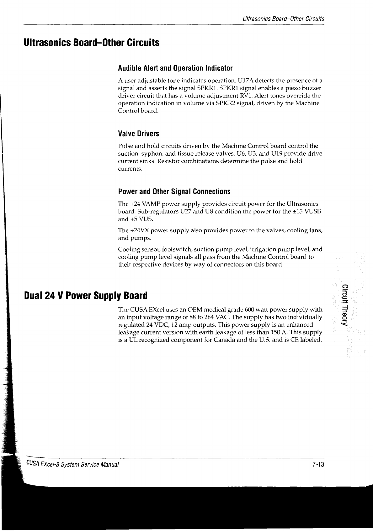
Ultrasonics
Board-Other
Circuits
Ultrasonics
Board-Other
Audible
A
signal
driver
operation
Control
Valve
Pulse
suction,
current
currents.
Power
The
board.
and
Circuits
Alert
user
adjustable
and
asserts
circuit
indication
board.
Drivers
and
hold
syphon,
sinks.
and
Other
+24
VAMP
Sub-regulators
+5
VUS.
and
Operation
tone
the
that
has a volume
in
circuits
and
Resistor
Signal
power
Indicator
indicates
signal
volume
driven
tissue
combinations
operation.
SPKR1.
adjustment
via
by
release valves.
Connections
supply
U27
provides
and U8
SPKR1
SPKR2
the
Machine
determine
circuit
condition
U17A
detects
signal
RV1.
Alert
signal,
Control
U6,
U3,
the
power
the
power
the
presence
enables a piezo
tones
override
driven
board
and
U19
pulse
for
by
the
control
provide
and
hold
the
Ultrasonics
for
the
Machine
+15
of
buzzer
the
the
drive
VUSB
a
Dual
24 V Power
The
and
Cooling
cooling
their
Supply
The
an
regulated
leakage
is a UL
+24VX
pumps.
sensor,
pump
respective
Board
CUSA
input
voltage
24
current
recognized
power
footswitch,
level
devices
EXcel
uses
range
VDC,
version
supply
12
component
also
signals
by
way
an
OEM
of
88
amp
outputs.
with
suction
all
provides
pass
of
connectors
medical
to
264
earth
for
Canada
power
pump
level,
from
the
grade
VAC.
The
This
power
leakage
to
irrigation
Machine
on
600
supply
supply
of
less
and
the
the
valves,
Control board
this
board.
watt
power
has
two
is
than
150
U.S.
and
cooling
pump
level,
supply
individually
an
enhanced
A.
This
supply
is
CE
labeled.
fans,
and
to
una
with
Aoel」
È:
CUSA
Excel-8
System
Service
Manual
TAS
Page 98

Checkout
Procedures
In
this
section:
¢
Inspections
4
Footswitch
4
Power
cord
*
Power
on
verification
*
Handpiece
test
(optional).
Inspections
CUSA
EXcel-8
System
Service
When
inspect
1.
Manual
you
have
the
footswitch
Footswitch
Disconnect
Inspect
Inspect
Inspect
Clean
Allow
Connect
the
the
the
the
footswitch
the
footswitch
the
unpacked
and
the
footswitch
connector
footswitch
cable
footswitch
for
for
cuts,
and
to
the
the
from
damage
for
damage.
tears,
cable
dry.
to
the
console,
power
cord.
the
or
or
excessive
with a damp
console
and
at
regular
console
corrosion.
(rear
compression.
cloth
(rear
panel).
intervals
panel).
and
mild
afterward,
detergent.
8-1
Page 99

Power
On
Verification
Power
On
Power
1.
Unplug
2.
Inspect
tight.
3.
Inspect
4.
Clean
5.
Allow
6.
Plug
Verification
1.
Connect
2.
Plug
3.
Turn
panel
4.
Turn
5.
The
Alert
Cord
the
system
for
damage
the
cord
the
power
the
power
the
power
the
footswitch.
the
system
on
(|)
the
indicators
on
(|)
the
front
panel
indicators
power
or
corrosion.
for
damage.
cord
with a damp
cord
to
dry.
cord
into a wall
power
AC
momentarily
System
indicators
(red,
Main
left
cord
Switch,
Power
side
cord
from
the
Ensure
cloth
receptacle.
into a wall
located
flash.
Switch,
momentarily
of
control
wall
receptacle.
that
the
and
mild
receptacle.
on
the
rear
located
flash.
panel)
on
The
illuminate.
connector
detergent.
panel.
the
front
Handpiece
screws
The
front
panel.
and
are
Handpiece
Test
(Optional)
To
perform
the
following
Tip
O-rings
Nosecone
Flue.
For
complete
Assembling
User's
Notice
To
avoid
the
torque
this
the
Guide.
product
wrench
test,
you
need a handpiece.
components
information
Handpiece
damage,
to
in a Nonsterile
tighten
onto
the
on
assembling
NEVER
or
hold
loosen
Further,
handpiece:
the
handpiece,
Area,
in
the
handpiece
the
tip.
the
you
CUSA
in
your
must
refer
EXcel
hand
assemble
to
Section
System
while
using
9,
ο.
CUSA
EXcel-8
System
Service
Manual
Page 100

To
test
1.
Plug
2.
Confirm
main
the
the
handpiece,
the
power
that
switch
rear
panel
follow
cord
the
AC
located
is
on
this
into a wall
on
(|).
procedure:
receptacle.
|
Handpiece
AC
Main
Test
Switch
(Optional)
3.
Fill
4.
Slide
reservoir
the
until
the
cooling
the
cooling
into
console
it
snaps
water
the
side
into
water
slot
panel
place.
reservoir
on
fi
$
CU
with
=
aa
7
“Woe
1000
coast
cc
distilled
a,
water.
CUSA
EXcel-8
System
Service
Manual
1105945)
5910р99024
 Loading...