

Page 1
RF Receiver
RFR-6
Instruction Manual
Contents
Introduction.............. 3
About the RFR-6 ..................... 3
Applications ........................... 3
Installation................ 4
Working angle and range of
the IR blaster....................... 4
Mounting ................................ 5
Using the mono cable and
the IR emitters..................... 6
Connecting Integra/Onkyo
components equipped
with IR IN terminal .............. 6
How to use the emitters ........ 7
Connecting the Power
Adapter .............................. 7
Settings .................................... 8
RF Interference ....................... 8
Thank you for purchasing the Integra RF
Receiver. Please read this manual
thoroughly before making connections
and plugging in the unit. Following the
instructions in this manual will enable you
to obtain optimum performance. Please
retain this manual for future reference.
Troubleshooting ....... 9
Specifications .......... 10
En
Page 2
Precautions
Care
From time to time you should wipe the unit
with a soft cloth. For heavier dirt, dampen a
soft cloth in a weak solution of mild detergent
and water, wring it out dry, and wipe off the
dirt. Following this, dry immediately with a
clean cloth. Do not use rough material, thinners,
alcohol or other chemical solvents or cloths
since these could damage the finish.
FCC Information for User
CAUTION:
The user changes or modifications not expressly approved by the party responsible for
compliance could void the user’s authority to
operate the equipment.
NOTE:
This equipment has been tested and found to
comply with the limits for a Class B digital device, pursuant to Part 15 of the FCC Rules.
These limits are designed to provide reasonable
protection against harmful interference in a
residential installation. This equipment generates, uses and can radiate radio frequency energy and, if not installed and used in accordance
with the instructions, may cause harmful interference to radio communications. However,
there is no guarantee that interference will not
occur in a particular installation. If this equipment does cause harmful interference to radio
or television reception, which can be determined by turning the equipment off and on, the
user is encouraged to try to correct the interference by one or more of the following measures:
• Reorient or relocate the receiving antenna.
• Increase the separation between the equipment and receiver.
• Connect the equipment into an outlet on a
circuit different from that to which the receiver is connected.
• Consult the dealer or an experienced radio/
TV technician for help.
NOTE:
If serial or parallel ports are configured, a filtered/shielded serial or parallel cable is recommended to minimize EMI and ensure FCC B
compliance.
This device complies with Part 15 of the FCC
rules. Operation is subject to the following two
conditions:
(1) This device may not cause harmful interference, and (2) this device must accept any interference received, including interference that
may cause undesired operation.
Changes or modifications not expressly approved by the party responsible for compliance
void the user’s authority to operate the equipment.
For Canadian models
NOTE: THIS CLASS B DIGITAL APPA-
RATUS COMPLIES WITH CANADIAN
ICES-003.
For models having a power cord with a polarized plug:
Modèle pour les Canadien
REMARQUE: CET APPAREIL
NUMÉRIQUE DE LA CLASSE B EST CONFORME À LA NORME NMB-003 DU
CANADA.
2
Page 3
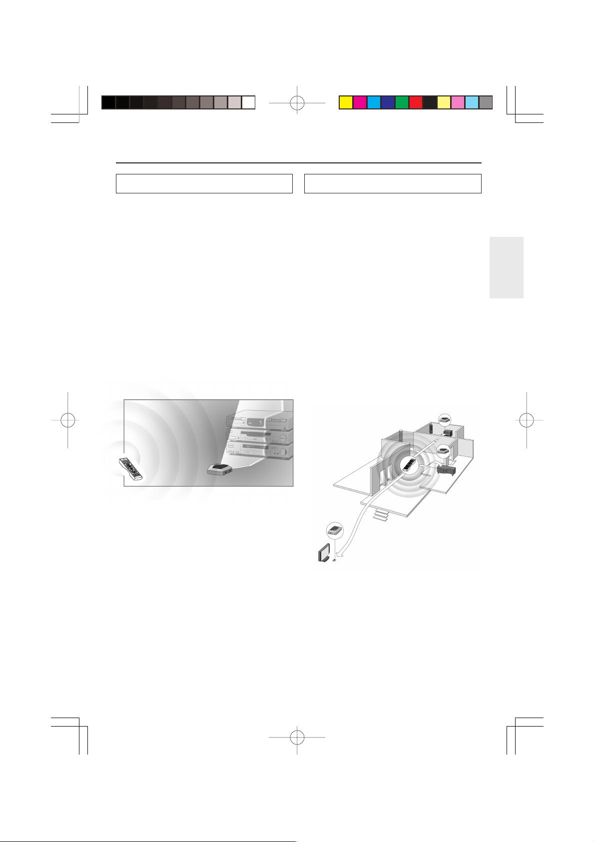
Introduction
About the RFR-6
Most remote controller systems have to be operated by pointing the remote controller directly
towards a device. Any obstacle between the remote controller and the device disturbs the operating signal. But what if you like to place your
devices inside a closed cabinet, a closet or even
in another room? The RFR-6 provides the solution to overcome obstacles like furniture or
walls. Your devices no longer have to be placed
in line of sight but can be operated from virtually any location. The RFR-6 is a RF Receiver
that is used in combination with the RF Remote
Controller. The RF Receiver receives radio fre-
quency (RF) signals sent out by the RF Remote
Controller and converts them into infrared (IR)
signals. These IR signals are then sent out to
your TV, DVD, preamplifier and so on.
RF signals
V
T
y
b
t
u
d
p
n
n
I
a
t
S
n
O
3
H
C
V
T
2
EF
D
1
C
AB
6
.-'/
@
5
NO
M
4
JKL
I
H
9
G
L
O
V
V
T
8
YZ
X
W
7
V
RF
TU
r
a
e
l
RS
C
Q
P
g
0
n
i
n
u
T
t
c
e
r
i
D
+
10
--
/
-
-
m
o
t
s
u
C
2
e
n
o
Z
o
r
c
a
t
M
Inpu
p
e
e
l
S
ode
M
r
e
M
e
m
n
m
u
i
D
u
n
e
M
p
u
A
d
i
o
o
A
D
T
/
J
V
T
o
e
d
i
V
L
O
V
r
e
t
n
E
H
C
c
s
i
D
e
d
i
u
G
E
x
i
t
p
u
t
e
S
R
e
g
t
u
n
i
r
n
t
u
M
y
a
l
p
s
i
D
m
o
d
n
a
R
w
o
l
S
/
p
e
t
S
c
e
R
y
r
o
m
e
M
t
s
a
L
gle
An
o
e
r
e
t
le
S
btit
u
S
T
S
H
C
l
l
A
y
udio
r
A
o
X
em
H
M
T
h
c
d
n
u
ear
o
S
r
r
u
S
P
S
D
-
B
A
P
S
D
eat
p
e
R
t
c
e
r
i
D
A
e
r
u
P
l
e
v
e
L
L
E
S
H
C
t
tis
Ar
e
n
o
T
t
s
e
T
bum
l
A
t
h
st
g
i
yli
N
L
Pla
L
E
S
o
i
d
u
A
u
g
n
a
L
te
ele
D
s
Cap
-
55
RC
Remote
+
l
e
v
e
L
e
r
n
Ge
Q
-
E
e
R
n
io
t
a
c
o
L
e
g
a
0M
Controller
RF Receiver
IR signals
Applications
The RF Receiver can be used in several
situations:
■ Your devices can be remotely controlled
while the RF Receiver is placed in line of
sight (situation A).
■ The RF Receiver controls devices placed in
an adjacent room (situation B).
■ The RF Receiver is placed inside a closet, a
rack, etc. together with your devices (situation C).
■ The set-ups in situation A, B and C can be
combined. If you want to control devices in
different locations, you have to place a RF
Receiver in each location. You can control
all RF Receiver with the same RF Remote
Controller. See Multiple RF Receiver on p. 8
to apply the necessary settings.
Situation B
O
n
Sta
nd
b
y
T
V
I
n
p
u
t
1
2
@
.
'
/
3
A
B
C
D
4
E
F
T
5
V
C
G
H
H
I
6
J
K
L
M
N
7
O
8
P
Q
R
S
9
T
U
V
+
W
1
X
0
Y
Z
T
V
0
V
--
O
/
-
L
--
C
l
e
a
r
D
C
i
r
u
e
c
s
to
t
T
u
m
n
i
n
g
M
a
c
r
o
Z
o
n
e
2
M
o
d
e
D
i
m
m
e
r
In
p
u
t
T
V
/
V
i
d
e
o
S
l
e
n
u
e
e
M
p
p
o
M
T
e
n
u
A
u
d
i
o
A
D
J
C
H
D
i
s
c
E
n
t
e
r
V
O
L
E
x
i
t
e
d
i
R
u
G
e
t
u
r
n
D
p
i
s
u
p
t
e
S
l
a
y
M
u
t
i
n
g
R
e
c
S
t
e
p
/
S
l
o
w
R
a
n
d
o
m
A
u
d
i
o
S
u
b
t
i
t
l
e
S
u
r
r
o
u
A
n
d
n
g
l
e
L
T
a
H
s
X
t
M
e
R
m
e
o
p
A
r
y
e
ll
C
a
H
t
S
T
A
-
S
t
B
e
r
e
P
o
u
r
e
S
e
A
a
r
c
h
D
i
r
e
M
c
e
t
m
o
r
y
D
S
P
D
S
P
T
e
s
t
T
o
n
e
C
H
S
E
L
P
l
a
y
l
i
s
L
t
e
v
e
l
-
A
l
b
u
m
L
e
v
e
l
+
A
r
t
i
s
t
A
G
u
d
e
i
o
n
S
E
r
L
e
C
a
p
s
L
N
i
g
h
D
t
e
l
e
t
e
R
e
E
Q
L
a
n
g
u
a
g
e
L
o
c
a
t
i
o
n
R
C
5
5
0
M
Situation A
Situation C
3
Page 4
Installation
The following components should be present:
RF Receiver, power adapter, Mono cable, 3 IR
emitters, mounting plate and 4 screws.
Before you install the RF Receiver, you should
decide which of the set-ups described on p. 3 apply to your needs. It is recommended to read
through this manual entirely.
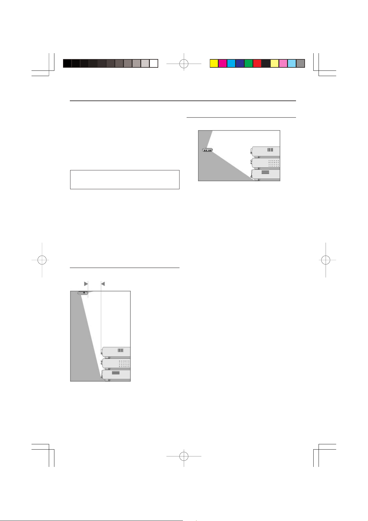
Working angle and range of the IR
blaster
The IR signals sent out by the RF Receiver always have to be able to reach the remote control
sensor of your devices. Make sure that the IR
blaster (dark plastic window on top of the RF
Receiver) is aimed at your devices.
To get optimal results, it is recommended to
place the RF Receiver horizontally with the IR
blaster facing up or down.
IR blaster facing down
Minimum distance: 4 inches
(10 cm)
IR blaster facing up
Maximum distance: 16 feet (5 m)
Figure 2
Figure 2 represents the RF Receiver with the IR
blaster facing up. The RF Receiver can be placed
at a distance and higher than your devices. Make
sure there are no objects between the RF Receiver and the remote control sensor of the devices.
Figure 1
Figure 1 represents the RF Receiver mounted up
side down inside a closet. Always maintain a
minimum distance of 4 inches (10 cm) between
the RF Receiver and your devices.
4
Page 5

Installation
Mounting
The RF Receiver can be mounted to a ceiling, a
rack, etc. using the included mounting plate and
the 4 screws. Take into account the range and
the working angle of the IR blaster as explained
on p. 4. Also make sure to place the RF Receiver
in a central position aimed directly at your devices.
Note:
It is adviced not to place the RF Receiver inside
a metal closet as RF signals can be disturbed by
metal objects.
1Screw the plate to a rack, closet, etc.
Provide sufficient space to connect the
power adapter and to slide the RF Receiver
back on.
Note:
Depending on the surface, it may be possible
to attach the RF Receiver to the ceiling, the
rack, etc. using a piece of 2-sided tape. Look
for the right position and make sure there is
sufficient space.
2 Slide the RF Receiver on the
mounting plate.
5
Page 6

Installation
Using the mono cable and the IR
emitters
Like the IR blaster of the RF Receiver, the 1/8
inch (3.5 mm) mono cable and the IR emitters
send out IR signals. You can use the mono cable
and the IR emitters as an alternative for the IR
blaster.
You can use the mono cable to connect an Integra/Onkyo component that has an IR IN terminal.
Note:
It is adviced not to place the RF Receiver inside
a metal closet as RF signals can be disturbed by
metal objects.
When to use the mono cable and the
emitters
The mono cable and the IR emitters can control
devices the IR blaster cannot reach, for instance
when there is limited space around the remote
control sensor of the devices, e.g. in a small
closet.
Note:
The mono cable and the IR emitters can also be
used in combination with the IR blaster of the
RF Receiver. All send out IR signals simultaneously. This allows you to operate several devices using all the IR blaster, the mono cable and
the IR emitters.
Connecting Integra/Onkyo
components equipped with IR IN
terminal
The 1/8 inch (3.5mm) mono cable (included
with the RF Receiver) can be used to connect the
RF Receiver to Integra/Onkyo components
equipped with IR IN terminal for controlling the
Integra/Onkyo components.
1 Connect the supplied 1/8 inch
(3.5 mm) mono cable to the IR IN
terminal on your Integra/Onkyo
component.
1/8 inch
(3.5 mm)
mono cable
I R
IN
OUT
Integra/Onkyo
components
2 Plug the other end of the cable into
the RF Receiver.
Note:
IR terminals are different than
connectors on
Integra/Onkyo components. Do not connect IR
terminals to
connectors on Integra/Onkyo
components.
6
Page 7

Installation
How to use the emitters
The IR emitters can be attached to the surrounding surface facing the remote control sensor or
directly to the remote control sensor.
1 Attach the emitters to a surface
above, below or in front of the remote
control sensor of your devices (for
aesthetic appearance or when it is
difficult to locate the remote control
sensor).
–OR–
Attach the emitters directly to the
remote control sensor of your
devices.
Connecting the Power Adapter
When connecting the power adapter it is recommended that you plug the adapter into the RF
Receiver before you plug it into the socket.
When connected you will see a red LED on the
RF Receiver.
Note:
To avoid interference, the adapter cable should
be kept away from the RF Receiver as far as
possible.
2 Plug the IR emitters into the RF
Receiver.
To avoid interference, the wires of the emitters should be kept away from the RF Receiver as far as possible.
7
Page 8

Installation
Settings
As the RF Receiver “communicates” with the
RF Remote Controller, you have to set the same
Receiver ID (identity) on both appliances. The
settings depend on whether you have a single RF
Receiver or multiple RF Receiver.
Single RF Receiver
When you use only one RF Receiver, you can
accept the default setting for the Receiver ID
(ID=0). Make sure your RF Remote Controller is
set to the same default setting (see the RF Remote Controller’s manual for more details).
Multiple RF Receiver
If you want to operate several of your devices independently, e.g. grouped on different locations,
you will need multiple RF Receiver. When using
several RF Receiver, it is important to assign a
unique Receiver ID to each RF Receiver. 16 Receiver IDs (from 0 to 9 and from A to F) can be
assigned.
1 Choose an Receiver ID for the RF
Receiver by turning the ID dial with a
small screwdriver.
3 Try to operate your devices with the
RF Remote Controller.
The red LED will blink when the RF Receiver receives a correct command.
4 Repeat this procedure for every RF
Receiver.
RF Interference
If your devices are not responding to commands
or if the red LED on the IR blaster is blinking
without sending commands, it might be possible
that there is RF interference. This can be the
case when other RF appliances are operated
nearby, for instance by your neighbours.
When you notice RF interference, you have to
choose another channel on your RF Receiver. 4
channels (CH from 0 to 3) can be assigned.
1 Choose a channel for the RF Receiver
by turning the CH dial with a small
screwdriver.
2 On the RF remote controller, choose
the same channel for each device
controlled by the RF Receiver.
Refer to the RF Remote Controller’s manual
for more information.
2 On the RF Remote Controller, choose
the same Receiver ID for each device
controlled by the RF Receiver.
Refer to the RF Remote Controller’s manual
for more information.
8
3 Try to operate your devices with the
remote controller.
Page 9

Troubleshooting
Devices do not respond properly
■ Check if the power adapter is connected and
the red LED is on.
■ Check if the ID and channel numbers on the
RF Receiver match with the ID and channel
numbers on the RF Remote Controller (see
p. 8). Refer to the RF Remote Controller’s
manual for more details on the settings of the
Remote Controller.
■ Check the placement of the RF Receiver:
• Check the distance between the RF Re-
ceiver and the RF Remote Controller (see
p.4).
• Check the range and the working angle of
the IR blaster (see p. 4).
• Check if the RF Receiver is placed in a
central position relative to your devices.
• Make sure that the distance between the
RF Receiver and your device is at least 4
inches (10 cm).
• Make sure that the distance between the
RF Receiver and your device is at most 16
feet (5 meters).
• Make sure the IR signals between the RF
Receiver and the remote control sensor of
your devices are not disturbed by any objects.
• Check if metal objects, for instance a
metal closet, wires or cables, surrounding
the RF Receiver do not disturb the RF signals.
• If you are using the 1/8 inch (3.5 mm)
mono cable, make sure to plug in all the
way to make a good connection.
• If you are using the IR emitters, make
sure they are connected properly and that
they are placed within range of the remote
control sensor (see p. 7).
The red LED on the RF Receiver blinks
without using the RF Remote Controller
■ This indicates RF interference. Another device in the proximity is sending out RF signals. Change the channel (CH) on the RF
Receiver (see p. 8).
There is no red LED on my RF Receiver
■ Check if the power adapter is connected
properly.
The IR emitters are no longer adhesive
■ Replace the adhesive with a fresh piece of
the 2-sided tape.
I cannot find the exact location of the
device’s remote control sensor
■ Check the manual of the device.
When still in doubt, contact your supplier or
the manufacturer.
■ It might be possible that some commands
cannot be sent out as RF signals. In that case
you will have to reconfigure the RF Remote
Controller to operate your devices with IR
signals again.
9
Page 10

Specifications
The specifications and design of this product are subject to change without notice.
Hardware
Dimensions
Operating temperature
IR frequency range
Radio frequency (RF)
Cable
IR emitters
Accessories
Approvals
Red LED (continuously on when powered, blinking during RF reception)
16 IDs and 4 CHs
4 outputs for mono cable and IR emitters
Possibility to have multiple RF Receiver in one home not interfering
Positioning: freestanding, mounted horizontally or hanging up side down
4.5 x 3.2 x 1.2 inch (113 x 81 x 30 mm)
32 ˚F to 122 ˚F (0 ˚C to 50 ˚C)
Operating distance: 16 feet (5 meters)
IR frequency range: DC/flash codes, 36kHz-550kHz
Operating distance: approximately 100 feet (30 meters) depending on the
surrounding conditions
Frequency: 433.92 MHz
1/8 inch (3.5 mm) mono male to male
cable length: 7 feet (2.0 meters)
Number of IR emitters : 3
1/8 inch (3.5 mm) mono mini-plug
Cable length: 7 feet (2.0 meters)
Max. range: 3 feet (75 cm)
120V AC Power adapter (for USA and Canada)
230V AC Power adapter (for Europe and Australia)
Mounting kit (Plate and 4 screws)
The device complies with part 15.19(a)(3) of the FCC Rules.
Operation is subject to the following two conditions: (1) this device may
not cause harmful interference and (2) this device must accept any
interference received including interference that may cause undesired
operation.
10
Page 11

Memo
11
Page 12

Integra Division of
ONKYO U.S.A. CORPORATION
18 park Way, Upper Saddle River, N.J. 07458, U.S.A.
Tel: 201-785-2600 Fax: 201-785-2650 http://www.integrahometheater.com
Integra Division of
ONKYO CORPORATION
Sales & Product Planning Div.: 2-1, Nisshin-cho, Neyagawa-shi, OSAKA 572-8540, JAPAN
Tel: 072-831-8023 Fax: 072-831-8124
SN 29343618
(C) Copyright 2003 ONKYO CORPORATION Japan. All rights reserved.
I0308-1
 Loading...