

Page 1
RDA-7.1
SERVICE MANUAL
Ref. No. 3804
SERVICE MANUAL
SEVEN CHANNEL AMPLIFIER
MODEL RDA-7.1
Nov, 2004
120 V AC, 60HzADD
230-240 V AC, 50HzAPP
APA
230-240 V AC, 50Hz
220-230 V AC, 50/60HzAGT
AGK
220-230 V AC, 50/60Hz
SAFETY-RELATED COMPONENT
WARNING!!
COMPONENTS IDENTIFIED BY MARK ON THE
SCHEMATIC DIAGRAM AND IN THE PARTS LIST ARE
CRITICAL FOR RISK OF FIRE AND ELECTRIC SHOCK.
REPLACE THESE COMPONENTS WITH ONKYO
PARTS WHOSE PART NUMBERS APPEAR AS SHOWN
IN THIS MANUAL.
MAKE LEAKAGE-CURRENT OR RESISTANCE
MEASUREMENTS TO DETERMINE THAT EXPOSED
PARTS ARE ACCEPTABLY INSULATED FROM THE
SUPPLY CIRCUIT BEFORE RETURNING THE
APPLIANCE TO THE CUSTOMER.
Page 2

SPECIFICATIONS
AMPLIFIER SECTION
Number of channels :
Power :
Frequency response at -3 dB :
Input Impedance :
Input signal for max output power :
Input Sensitivity (Unbalanced) :
Input Sensitivity (Balanced) :
THD :
Damping Factor :
Power consumption
USA, Canada and some Asian model :
Other models :
Rated Speaker Impedance :
RDA-7.1
7
150 watts per channel min. RMS at 8 ohms, 2 channels
driven from 20 Hz to 20 kHz with no more than 0.1 % total
harmonic distortion (FTC).
300 watts per channel min. RMS at 4 ohms, 2 channels
driven at 1 kHz with no more than 0.1 % total harmonic
distortion (FTC).
350 W (EIAJ, 4 ohm, 1 kHz, 10 %)
300 W (DIN, 4 ohm, 1 kHz, 0.7 %)
3.5 Hz - 250 kHz
47 kohm each phase
1.2 V
100 mVrms
200 mV
0.03 % (20 Hz to 20 kHz)
40 at 8 ohm
15 A
10 A
4 ohms
GENERAL
Power Supply :
Dimensions (W x H x D) :
Weight :
Specifications and features are subject to change without notice.
Power supply and voltage vary depending on the area in which the unit is purchased.
AC 120 V, 60 Hz
AC 230 V, 50 Hz
AC 220 V, 50/60 Hz
450 x 197 x 602 mm
17-11/16" x 7-3/4" x 23-11/16"
52.5 kg, 115.7 lbs.
Page 3

SERVICE PROCEDURE-1
PRIMARY CONNECTIONS FOR DIFFERENT VOLTAGES
AC Board Jumpers
For voltages in the 100V - 120V range, install the two jumpers marked L.
For voltages in the 200V - 240V range, install the single jumper marked H.
Main Transformer Jumpers
The following connections should be made for different line voltages.
RDA-7.1
100V :
K1-3 to TB1-4
P7 to TB1-3
P2 to TB1-2
K2-3 to TB1-12
P8 to TB1-11
P3 to TB1-10
110V :
K1-3 to TB1-6
P7 to TB1-5
P2 to TB1-2
K2-3 to TB1-14
P8 to TB1-13
P3 to TB1-10
120V :
K1-3 to TB1-8
P7 to TB1-7
P2 to TB1-2
K2-3 to TB1-16
P8 to TB1-15
P3 to TB1-10
200V :
K1-3 to TB1-4
TB1-2 to TB1-3
K2-3 to TB1-12
TB1-10 to TB1-11
220V :
K1-3 to TB1-6
TB1-2 to TB1-5
K2-3 to TB1-14
TB1-10 to TB1-13
230V :
K1-3 to TB1-6
TB1-2 to TB1-7
K2-3 to TB1-14
TB1-10 to TB1-15
240V :
K1-3 to TB1-8
TB1-2 to TB1-7
K2-3 to TB1-16
TB1-10 to TB1-15
Page 4
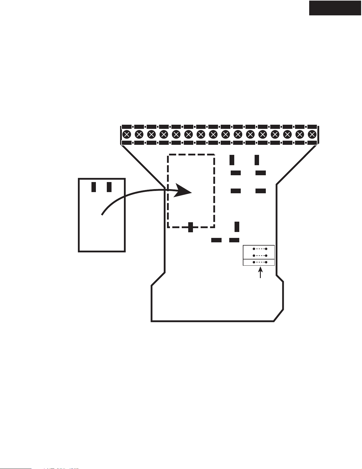
SERVICE PROCEDURE-2
PRIMARY CONNECTIONS FOR DIFFERENT VOLTAGES (Continued)
TB1
1 2 3 4 5 6 7 8 9 10 11 12 13 14 15 16
RDA-7.1
P2
P3
Inrush Current Limiter Board
(RDA-7-030-A)
P7
P8
K1-3 K2-3
P4
P9P1P10
AC Board (RDA-7-020-B)
Low
Jumpers
K2-4K1-4
L
L
HHigh
Page 5
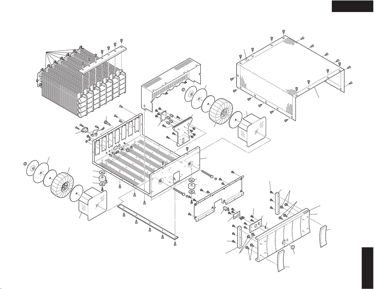
EXPLODED VIEWS-1
RDA-7.1
OVERALL
UN01
A35
B06
B03
A34
A52
A50
A51
B07
UN03
UN02
A52
A50
A51
A35
B02
B08
B05
B04
A635
A34
A22
x 4 pcs.
A21
B01
<Note>
A01 (Front panel ass'y) = A02 --- A08
A06
x 3 pcs.
A20
A05
A07
(10mm)
x 2 pcs.
A08
(14mm)
x 2 pcs.
A10
A02
A04
A06
x 3 pcs.
A05
A07
(10mm)
x 2 pcs.
A08
(14mm)
x 2 pcs.
A23
A03
RDA-7.1
Page 6
EXPLODED VIEWS-2
AMPLIFIER MODULE
RDA-7.1
B11
(Red)
A61
(Top)
B12
(Black)
A65
A62
(Bottom)
A60
(Base)
RDA-7.1
Page 7
EXPLODED VIEWS-3
SCREWS
RDA-7.1
A132 A131
A132 A131
A130
Cut
A132 A131
RDA-7.1
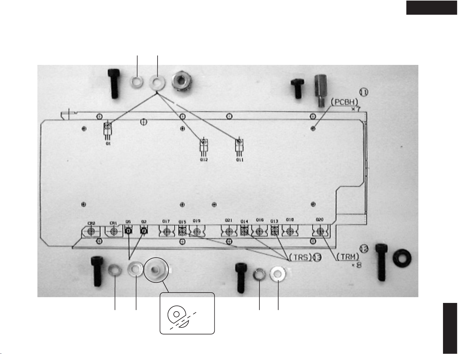
Page 8

EXPLODED VIEWS-4
SCREWS
RDA-7.1
14
GROU
Page 9
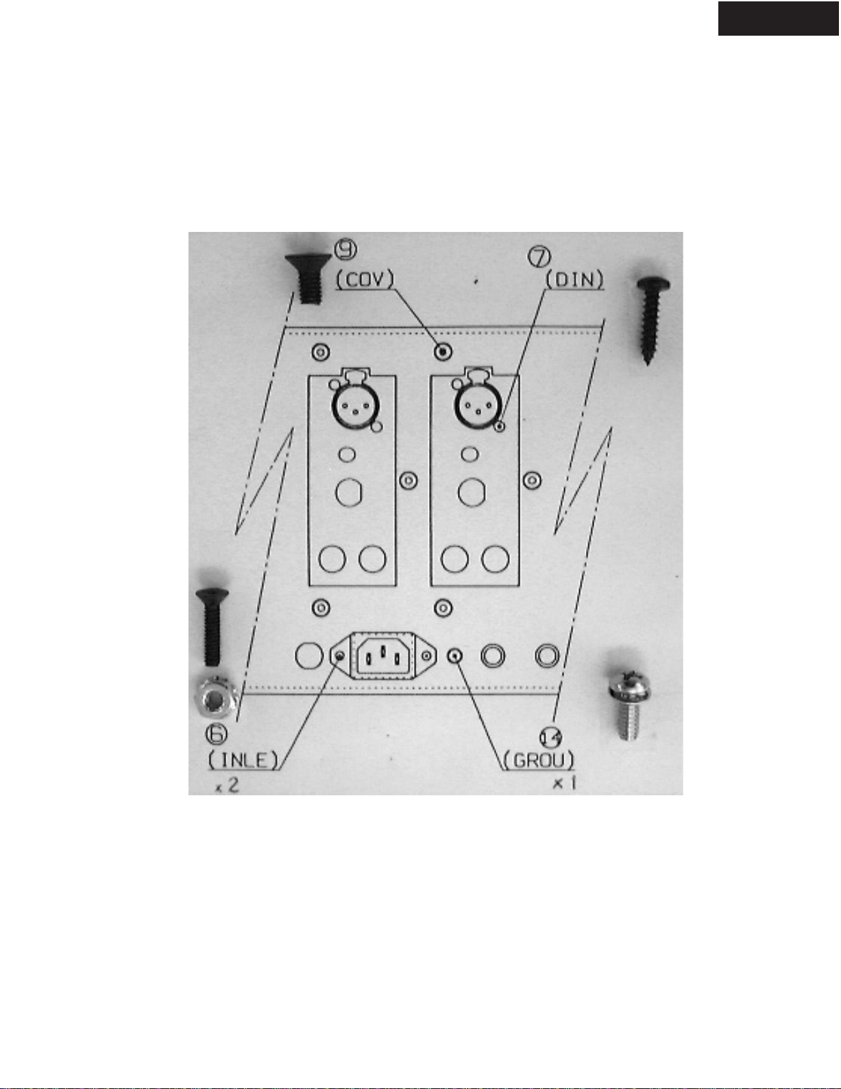
EXPLODED VIEWS-5
SCREWS
RDA-7.1
Page 10

RDA-7.1
A
SCHEMATIC DIAGRAMS-1
POWER SUPPLY
1
2
BCD
3
4
5
Page 11

RDA-7.1
A
SCHEMATIC DIAGRAMS-2
DRIVER CIRCUIT
1
2
BCD
3
4
C13 / C14
ROB C (For audio)
C13 / C14
5
C13a / C14a
C17 / C20
ROB C (For audio)
C17 / C20 C17a / C20a
Page 12

RDA-7.1
A
SCHEMATIC DIAGRAMS-3
OUTPUT STAGE AND PROTECTION
1
2
BCD
3
4
5
Page 13

RDA-7.1
A
SCHEMATIC DIAGRAMS-4
PROTECTION
1
2
BCD
3
4
5
Page 14

RDA-7.1
A
SCHEMATIC DIAGRAMS-5
AC BOARD
1
2
BCD
3
4
5
Page 15

RDA-7.1
A
SCHEMATIC DIAGRAMS-6
PROTECTION WIRING
1
2
BCD
3
4
5
Page 16

PRINTED CIRCUIT BOARD VIEWS-1
AMPLIFIER PC BOARD
RDA-7.1
A
1
2
3
4
5
BCDEFGH
AMPLIFIER PC BOARD (RDA-7-010-F)UN01
Side-A (Top)
Page 17

RDA-7.1
Page 18

RDA-7.1
PRINTED CIRCUIT BOARD VIEWS-1
AMPLIFIER PC BOARD
A
1
2
3
4
5
BCDEFGH
AMPLIFIER PC BOARD (RDA-7-010-F)UN01
Side-A (Top)
Page 19

PRINTED CIRCUIT BOARD VIEWS-2
AMPLIFIER PC BOARD
RDA-7.1
A
1
2
3
4
5
BCDEFGH
AMPLIFIER PC BOARD (RDA-7-010-F)UN01
Side-B (Bottom)
Page 20

RDA-7.1
Page 21

RDA-7.1
PRINTED CIRCUIT BOARD VIEWS-2
AMPLIFIER PC BOARD
A
1
2
3
4
5
BCDEFGH
AMPLIFIER PC BOARD (RDA-7-010-F)UN01
Side-B (Bottom)
Page 22

ADJUSTMENT PROCEDURE-1
BIAS & DC Offset Adjustment
Connect the assembled channel to the power transformer.
1.
Connect the power cord into an AC wall outlet.
2.
Turn ON the unit. After about 3 seconds the two green LED's should turn ON.
3.
Measure the following voltages and make sure they are within the specifications.
RDA-7.1
C7 (+)
C9 (-)
L1
Connect the DC voltmeter to the test points TP1 (-) and TP2 (+) and adjust the voltage to 4 mV using the R46 BIAS
4.
adjustment trimming resistor.
Allow the channel to warm up for 30 minutes, adjusting the bias currents every 10 minutes.
5.
Measure the output DC voltage and adjust it as close to zero as possible using the R24 trimming resistor.
6.
: 70 V +/- 3 V
: -70 V +/- 3 V
: 0 V +/- 0.1 V
Main Chassis Check
1.
Assemble the chassis / power supply.
2.
Connect the power cord into an AC wall outlet.
3.
Turn ON the unit. The blue ON LED should come ON.
4.
Turn OFF the unit and plug a remote control plug into the Remote IN jack.
5.
Turn ON the unit. The Red Standby LED should be ON.
6.
Apply 12V to the remote control plug. The unit should turn ON, the blue LED should be ON.
7.
Measure the secondary voltages on all power cables going to the channels. Each secondary should read 50 VAC
+/- 2 VAC.
Page 23

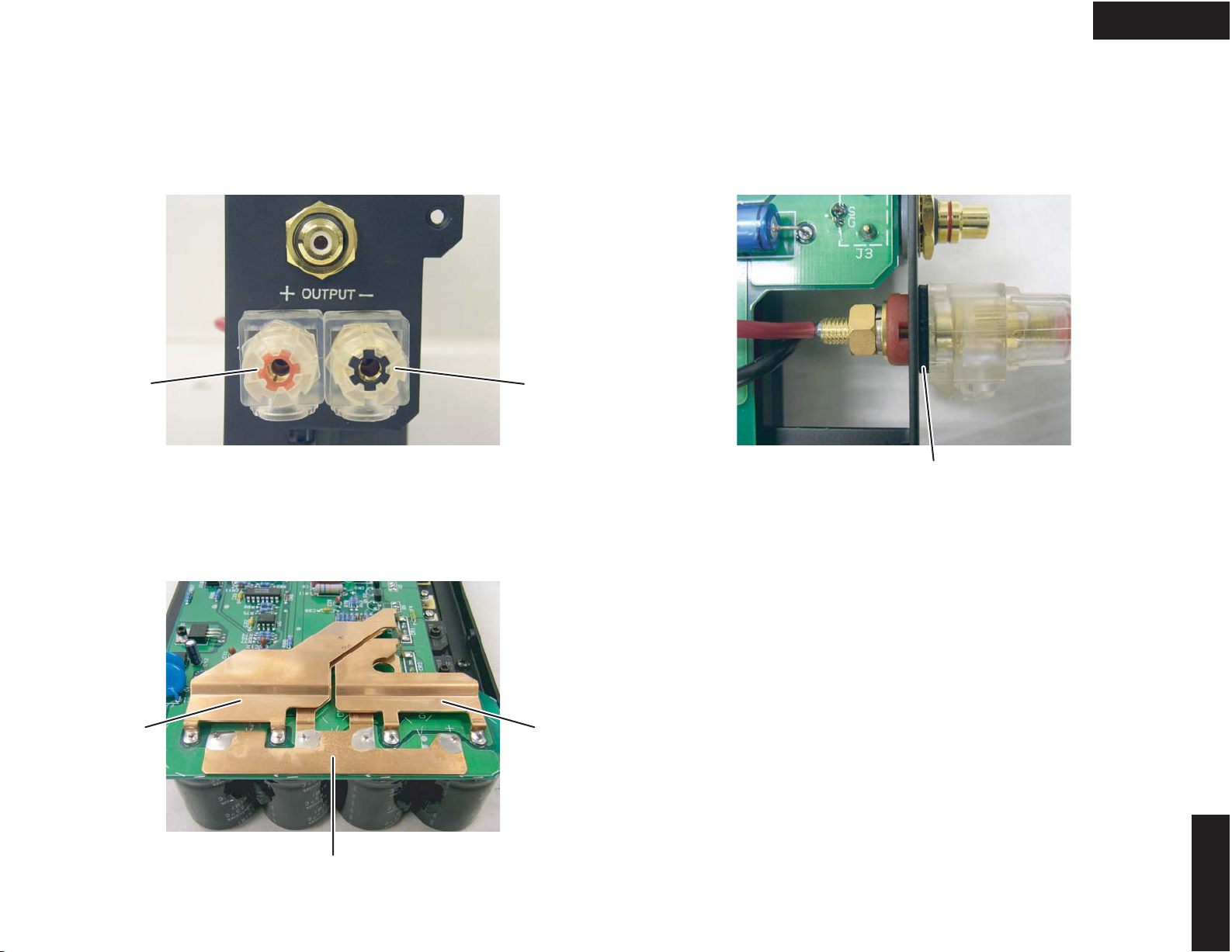
ADJUSTMENT PROCEDURE-2
Final Assembly Check
Check the screw which is the fixation of AMPLIFIER MODULE
when the electric conductivity between 1 and 2 is ruined.
RDA-7.1
Rear panel
FUSE
1
AC INLET
12V TRIGGER
IN OUT
2
Page 24

T
EXPLODED
EXPLODED
EXPLODED
EXPLODED
EXPLODED
EXPLODED
EXPLODED
EXPLODED
EXPLODED
EXPLODED
EXPLODED
EXPLODED
EXPLODED
EXPLODED
EXPLODED
EXPLODED
EXPLODED
EXPLODED
EXPLODED
EXPLODED
EXPLODED
EXPLODED
EXPLODED
EXPLODED
EXPLODED
EXPLODED
EXPLODED
EXPLODED
EXPLODED
EXPLODED
EXPLODED
EXPLODED
EXPLODED
EXPLODED
EXPLODED
EXPLODED
EXPLODED
EXPLODED
EXPLODED
1/4 PAGE
RDA-7.1
<Note>
Parts marked by "NSP" are generally unavailable because
they are not in our Master Spare Parts List.
NOTE : THE COMPONENTS IDENTIFIED BY THE MARK
! ARE CRITICAL FOR RISK OF FIRE AND
ELECTRIC SHOCK. REPLACE ONLY WITH PART
NUMBER SPECIFIED.
EXPLODED VIEWS PARTS LIS
REF. NO. PART NAME DESCRIPTION Q'TY PART NO. (SN) MARK
A01 F PANEL ASS'Y AS 1 27212607A
A02 F PANEL --- (1) 27212608A
A03 HANDLE (L) (1) 28158002
A04 HANDLE (R) (1) 28158004
A05 END CAP --- (2) 28125372
A06 SCREW 3P+6FN(BC) (6) 82143006
A07 SCREW 4TTC+10C(BC) (4) 830440109
A08 SCREW 4TTC+14C(BC) (4) 830440149
A10 BADGE (RESEARCH) 1 28135293
A20 FACET (1) 2 28198908
A21 GUIDE (POW) 1 27268013
A22 SCREW 3P+6FN(BC) 4 82143006
A23 KNOB (POW)AS 1 28325734
A34 SHLD PLT (PT) 2 27150462
A35 SHLD PLT --- 2 27150463
A50 LEG --- 4 27175402
A51 CUSHION --- 4 28141560
A52 CUSHION (LEG) 4 28141590
A60 RETAINER (BASE) 7 27141900
A61 RETAINER (T) 7 27141901
A62 RETAINER (B) 7 27141902
A65 RETAINER (S) 7 27141906
A635 LABEL LABEL(FLASH) 1 29360778
A130 BUSH (TOSHIBA AC331) 2 28170075
A131 WASHER W3 x 8F(BC) 8 87643008
A132 SP WASHER SW-3(SP-WASHER) 8 871130
B01 TOP COVER --- 1 14-ONK-0006
B02 TRANSFORMER 4ch 1 56-0041
B03 TRANSFORMER 3ch 1 56-0042
B04 SWITCH PLATE --- 1 14-ONK-0011
B05 POWER SWITCH TV-5, UL, VDE, SEMKO, 5A 1 51-0024
B06 AC INLET (UL APPROVED) 1 21-0091
B07 FUSE HOLDER (UL/CSA APPROVED) 1 43-0010
B08 CHASSIS (ADD, APP, APA, AGT, AGK, AJJ) 1 --- NSP
B11 SP TERMINAL (RED) 7 --- NSP
B12 SP TERMINAL (BLACK) 7 --- NSP
UN01 AMPLIFIER PC BOARD (RDA-7-010-F) 7 --- NSP
UN02 AC BOARD (RDA-7-020-B) 1 70-ONK-0002
UN03
INRUSH CURRENT LIMITER BOARD
(RDA-7-030-A) 1 --- NSP
!
!
!
!
!
Page 25

RDA-7.1
T
PRINTED CIRCUIT BOARD PARTS LIS
UN01 AMPLIFIER PC BOARD (RDA-7-010-F)
CIRCUIT NO. PART NAME DESCRIPTION Q'TY PART NO. (SN) MARK
PCB01
U1 IC LP2951CN (Voltage Regulator) 1 48-0097
PCB01
U2 IC LM317L (Voltage Regulator) 1 48-0098
PCB01
U3 IC LM317L (Voltage Regulator) 1 48-0098
PCB01
U4 IC LM385Z (Voltage Reference) 1 48-0099
PCB01
U5 PHT CP PS2502-1 1 24120092
PCB01
U6 IC TLC372CP (Dual Comparator) 1 48-0101
PCB01
U7 IC CD4013BCN (Dual D Flip-Flop) 1 48-0102
PCB01
U8 IC CD4025BCN (Triple 3 Input NOR) 1 48-0103
PCB01
U9 IC TLC555 8PIN DIP 1 48-0104
PCB01
U10 PHT CP PS2502-1 1 24120092
PCB01
Q1 TR MOS FET IRF620 or IRF621 1 48-0085
PCB01
Q2 TR IRF540 1 48-0087
PCB01
Q3 TR 2N5401 1 48-0088
PCB01
Q4 TR 2N5551 1 48-0089
PCB01
Q5 TR IRF5210 or IRF9540N 1 48-0086
PCB01
Q6 TR 2SC3381 1 48-0041
PCB01
Q7 TR 2SC3381 1 48-0041
PCB01
Q8 TR 2SA1349 1 48-0043
PCB01
Q9 TR 2N5550 1 48-0090
PCB01
Q10 TR 2N5400 1 48-0091
PCB01
Q11 TR 2SA1837 1 48-0092
PCB01
Q12 TR 2SC4793 1 48-0093
PCB01
Q13 TR MJF15030 1 48-0094
PCB01
Q14 TR MJF15030 1 48-0094
PCB01
Q15 TR MJF15031 1 48-0095
PCB01
Q16 TR 2SC5200-O 1 2202823
PCB01
Q17 TR 2SA1943-O 1 2202813
PCB01
Q18 TR 2SC5200-O 1 2202823
PCB01
Q19 TR 2SA1943-O 1 2202813
PCB01
Q20 TR 2SC5200-O 1 2202823
PCB01
Q21 TR 2SA1943-O 1 2202813
PCB01
Q23 TR MPS2222A 1 48-0096
PCB01
Q24 TR MPS2222A 1 48-0096
PCB01
CR1 DIODE RECTIFIER BRIDGE 10A 400V 1 48-0039
PCB01
CR2 DIODE RECTIFIER BRIDGE 10A 400V 1 48-0039
PCB01
CR6 DIODE SWITCHING 1N4150 1 48-0025
PCB01
CR7 DIODE SWITCHING 1N4150 1 48-0025
PCB01
CR8 DIODE SWITCHING 1N4150 1 48-0025
PCB01
CR10 DIODE SWITCHING 1N4150 1 48-0025
PCB01
CR11 DIODE SWITCHING 1N4150 1 48-0025
PCB01
CR12 DIODE SWITCHING 1N4150 1 48-0025
PCB01
CR13 DIODE DIP BRIDGE 1A 400V 4PIN 1 48-0011
PCB01
VR1 DIODE ZENER 30V 400mW 1N5256B 1 48-0015
PCB01
VR2 DIODE ZENER 24V 400mW 1N5252B 1 48-0036
PCB01
VR3 DIODE ZENER 24V 400mW 1N5252B 1 48-0036
2/4 PAGE
Page 26

PCB01
T
VR4 DIODE ZENER 24V 400mW 1N5252B 1 48-0036
PCB01
VR5 DIODE ZENER 24V 400mW 1N5252B 1 48-0036
PCB01
VR6 DIODE ZENER 12V 400mW 1N5242B 1 48-0084
PCB01
VR7 DIODE ZENER 12V 400mW 1N5242B 1 48-0084
PCB01
VR8 DIODE ZENER 24V 400mW 1N5252B 1 48-0036
PCB01
C3 ELECT C CE69W80V-10000M 1 3504395
PCB01
C4 ELECT C CE69W80V-10000M 1 3504395
PCB01
C5 ELECT C CE69W80V-10000M 1 3504395
PCB01
C6 ELECT C CE69W80V-10000M 1 3504395
PCB01
C7 ELECT C 100uF 100V 1 15-0104
PCB01
C9 ELECT C 100uF 100V 1 15-0104
PCB01
C13, C13a ROB C CE04W35V-100M(ROB) (For audio) 2 395861017
PCB01
C14, C14a ROB C CE04W35V-100M(ROB) (For audio) 2 395861017
PCB01
C17, C17a ROB C CE04W50V-22M(ROB) (For audio) 2 395882207
PCB01
C20, C20a ROB C CE04W50V-22M(ROB) (For audio) 2 395882207
PCB01
C40 ELECT C 100uF 100V 1 15-0104
PCB01
R24 TRIM R TRIMPOT 50 kohm (503) 1 46-0019
PCB01
R46 TRIM R TRIMPOT 25 Turn 500 ohm (501) 1 46-0020
PCB01
F3 FUSE LITTLE FUSE R251 015 F837-ND 1 43-0042
PCB01
F4 FUSE LITTLE FUSE R251 015 F837-ND 1 43-0042
PCB01
S1 SW NKKM2022S2A2G30 1 51-0035
PCB01
J2 JACK XLR NC3FAHL-2 1 21-0126
PCB01
J3 JACK RCA 1 21-0110
3/4 PAGE
UN02 AC BOARD (RDA-7-020-B)
CIRCUIT NO. PART NAME DESCRIPTION Q'TY PART NO. (SN) MARK
PCB02
U1 IC TLC555 8PIN DIP 1 48-0104
PCB02
Q1 TR MPS2222A 1 48-0096
PCB02
Q2 TR MPS2222A 1 48-0096
PCB02
CR1 DIODE DIP BRIDGE 1A 400V 4PIN 1 48-0011
PCB02
CR2 DIODE SWITCHING 1N4150 1 48-0025
PCB02
CR3 DIODE SWITCHING 1N4150 1 48-0025
PCB02
CR4 LED SEL2E10C (BLUE) 1 225374
PCB02
F2 FUSE LITTLE FUSE R251 001 F826-ND 1 43-0043
PCB02
T1 TRANSFORMER MICROTRAN MT3101 1 56-0168
PCB02
K1 RELAY 821-W-1A-C 12V DC 1 51-0009
PCB02
K2 RELAY 821-W-1A-C 12V DC 1 51-0009
RDA-7.1
PACKING PROCEDURE PARTS LIS
REF. NO. PART NAME DESCRIPTION Q'TY PART NO. (SN) MARK
PACKING
PACKING
PACKING
PACKING
PACKING
PACKING
PACKING
PACKING
PACKING
01 INNER CARTON RDA-7.1 1 34-ONK-0001
02 PAD L & R 1 --- NSP
03 POLY BAG --- 1 34-0010
04 WARNING LABEL --- 1 --- NSP
05 LABEL (PE-LD) 1 29361573
06 TAPE (SEROHAN) NITTO NO.29 (1) 29110149
07 POLY BAG 350 x 250 2 29100097-1A
08 INS MANUAL E(RDA7.1) 1 29343637A <ADD>
08 INS MANUAL E(RDA7.1) 1 29343637A <APP>
!
!
Page 27

4/4 PAGE
PACKING
PACKING
PACKING
PACKING
PACKING
PACKING
PACKING
PACKING
PACKING
PACKING
PACKING
PACKING
PACKING
PACKING
PACKING
PACKING
PACKING
PACKING
PACKING
08 INS MANUAL E(RDA7.1) 1 29343637A <APA>
08 INS MANUAL E(RDA7.1) 1 29343637A <AGT>
08 INS MANUAL E(RDA7.1) 1 29343637A <AGK>
09 INS MANUAL U6(RDA-7.1) 1 29343638A <APP>
10 INS MANUAL T(RDA-7.1) 1 29343639A <AGT>
11 WRNTY CARD (RESEARCH) 1 29365091A <ADD>
12 AC CORD --- 1 --- NSP
13 PLUG CORD 3.5-MINI PLUG (RI) 1 2010200
14 OUTER CARTON RDA-7.1 1 34-ONK-0002
15 UPC LABEL --- (1) 29363591 <ADD>
15 EAN LABEL --- (1) 29363590 <APP>
15 EAN LABEL --- (1) 29363590 <APA>
15 EAN LABEL --- (1) 29363590 <AGT>
15 EAN LABEL --- (1) 29363590 <AGK>
16 PP TAPE W50 (1) 29110071 or
16 PP TAPE W48 OPP TAPE (1) 29110148 or
16 PP TAPE NITTO 3703 SUPER W50L100 (1) 29110176
17 DESTINATION LABEL --- (2) --- NSP
18 INST SHEET E(RDA-7.1) 1 29355513
Page 28

PACKING PROCEDURE-1
INNER CARTON
06
02
03
RDA-7.1
02
05
04
FRONT SIDE
01
Inner carton
08
18
09
11
10
12
Inner carton
13
07
07
06
06
Page 29

PACKING PROCEDURE-2
RDA-7.1
OUTER CARTON
15
RDA-7.1
R E S E A R C H
RDA-7.1
16
R E S E A
C H
R
RDA-7.1
Inner carton
15
RDA-7.1
14
Outer carton
16
RDA-7.1
RDA-7.1
17
16
 Loading...