

Page 1
IMPORTANT
Please Read
®
MAYFIELD
Innity XR2 Base Unit
( #A2079)
Instruction Manual
Rx Only
Integra LifeSciences Corporation
4900 Charlemar Drive, Building A, Cincinnati, OH 45227, USA
Tel: 1-513-533-7979 Fax: 1-513-271-1915
www.Integra-LS.com
Integra NeuroSciences, Limited
Newbury Road, Andover, Hampshire SP10 4 DR, England
Tel: +44 (0) 1264 345 700 Fax: +44 (0) 1264 332 113
MAYFIELD® is a registered trademark of SM USA, Inc.
and is used by INTEGRA LIFESCIENCES Corporation under license.
Page 2

Meaning Of Symbols Used In This Manual - ENGLISH
CAUTION!
WARNING!
Hazards which could result in equipment or property damage.
Hazards which could result in severe personal injury or death.
Attention, consult accompaning documents.
Conforms to the European Medical Device Directive (MDD).
Manufacturing site.
European Representative.
Refer to Instruction Manual
Rx Only Caution: Federal (USA) Law restricts this Device to sale by or
on the order of a Licensed practitioner
REF
Product catalog number
Page 3
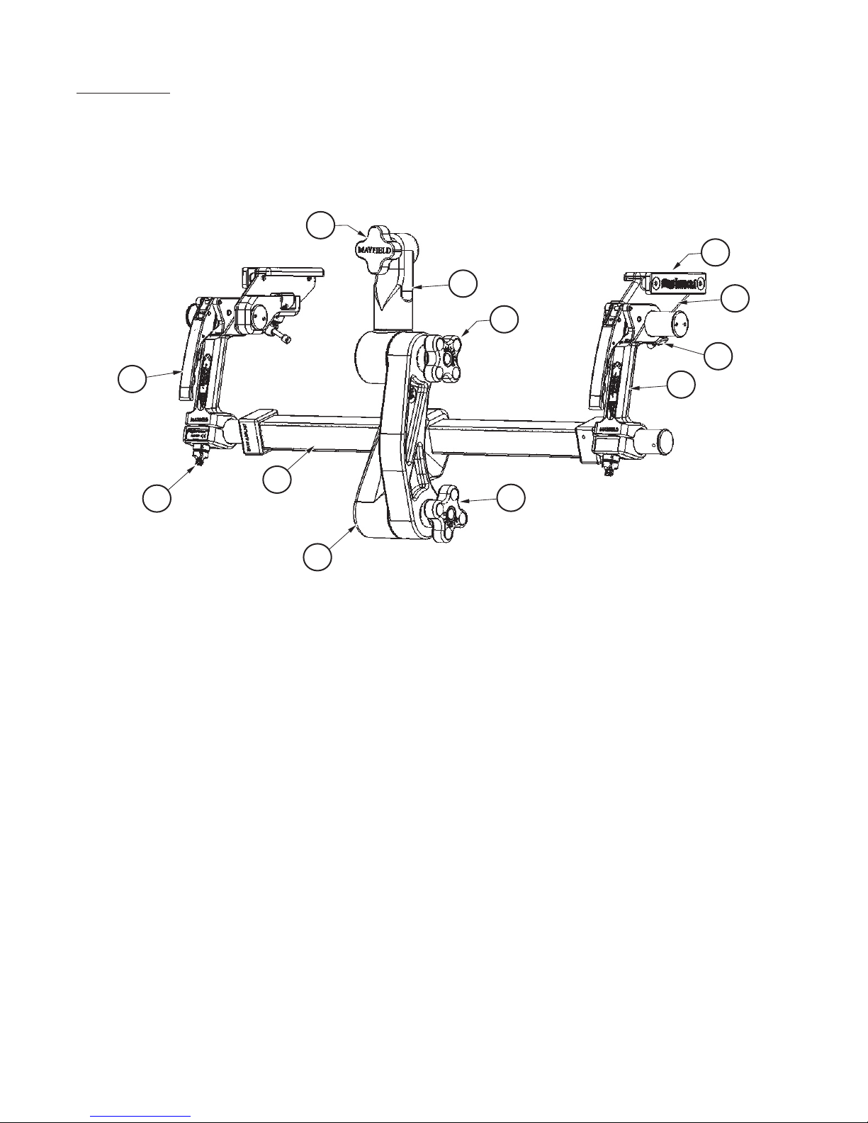
Inspection
Always inspect instruments before and after use. If a component appears damaged and/or does
not seem to function properly, do not use the device and immediately send the instrument to
Integra LifeSciences, Cincinnati, Ohio or an authorized Integra repair center for evaluation, repair
or replacement.
1
10
2
3
11
8
5
9
3
6
7
4
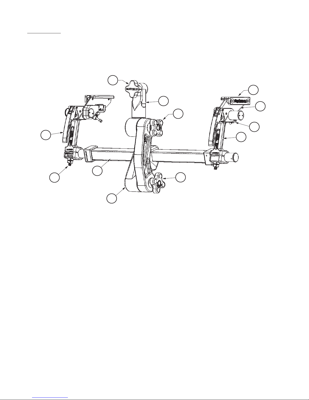
1. Skull Clamp/Headrest Locking Knob
2. Swivel Adaptor
3. Link Arm Locking Knobs
4. Yoke
5. Crossbar
6. Base Handle
7. Side Rail Bracket
8. Locking Lever
9. Base Handle Adjustment Knob
10. Auxilliary Side Rail
11. Side Rail Bracket Locking Knob
Figure 1 A2079 Innity XR2 Base Unit Components
Page 1
Page 4

Indication For Use
WARNING!
CAUTION!
The Innity XR2 Base Unit is intended to be used to support a patient during diagnostic
examination and/or surgical procedures where a rigid support between surgical table and
headrest, or skull clamp is necessary, positional freedom is required and where X-ray imaging
modalities will be used.
Failure to read and follow the instructions furnished in this product insert may
result in serious patient injury.
Do not steam sterilize; components may be damaged by high heat leading to
device damage and reduced performance.
The headrest or skull clamp must be securely fastened to the base unit. Failure
to fully tighten all adjustment portions of this or any similar device may result
in serious patient injury.
The user must make sure that any threaded connections are secure and
starbursts have meshed (where applicable) after adjustments are complete.
Failure to do so may result in serious patient injury.
Always make sure the base unit is properly secured to the operating table.
The base unit must not be used if the device appears to be damaged or
functioning incorrectly.
Over-tightening the mechanisms adjustment screws may result in damage to
the unit.
Over extending or overloading the base unit may result in unintended
movement, shortened product life and/or damage to the unit.
Do not alter the construction of this device as it may result in serious patient
injury.
Page 2
Page 5

Description
The MAYFIELD Innity XR2 Base Unit is designed to provide attachment from the operating room
table to MAYFIELD Skull Clamps for rigid skeletal xation or MAYFIELD Horseshoe Headrests for
procedures where support only is required and not rigid xation. The XR2 Base Unit is designed
for patient positioning in the prone, lateral or supine positions for attachment to either a skull
clamp or a horseshoe headrest. It attaches to the OR table side rails with easy adjustment for
tables of a variety of widths.
The Innity XR2 Base Unit is suitable for Digital Subtraction Angiography (DSA), Fluoroscopy and
CT imaging modalities.
The components of the XR2 Base Unit are color-coded for easy assembly for use and disassembly
for cleaning and storage. A separate storage case is provided with the base unit for safe-keeping
between procedures and for use to ship the product in for repair or maintenance.
A separate, optional Tri-Star Swivel Adaptor (A2111) is available for use with the XR2 Base Unit
when image-guided surgery (IGS) systems are used in the procedures. The Tri-Star Swivel
Adaptor provides two extra starbursts for attachment of the ancillary IGS equipment. See the
separate Instruction Manual for the A2111 for information.
The Innity XR2 Base Unit is designed for use with the following equipment:
A2114 MAYFIELD Innity XR2 Skull Clamp
A2002 MAYFIELD 2000 Radiolucent Skull Clamp
A2111 MAYFIELD Innity XR2 Tri-Star Swivel Adaptor
A1058 MAYFIELD Radiolucent Skull Clamp
A2010 MAYFIELD Radiolucent Horseshoe Headrest
A2011 MAYFIELD Pediatric Radiolucent Horseshoe Headrest
NOTE: Use of MAYFIELD products and accessories in conjunction with other
manufacturer’s stabilization equipment is not recommended.
Page 3
Page 6
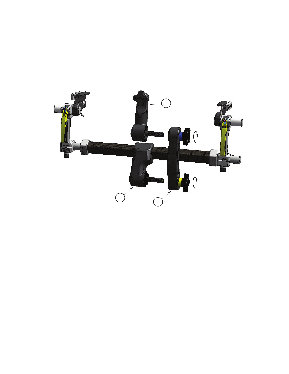
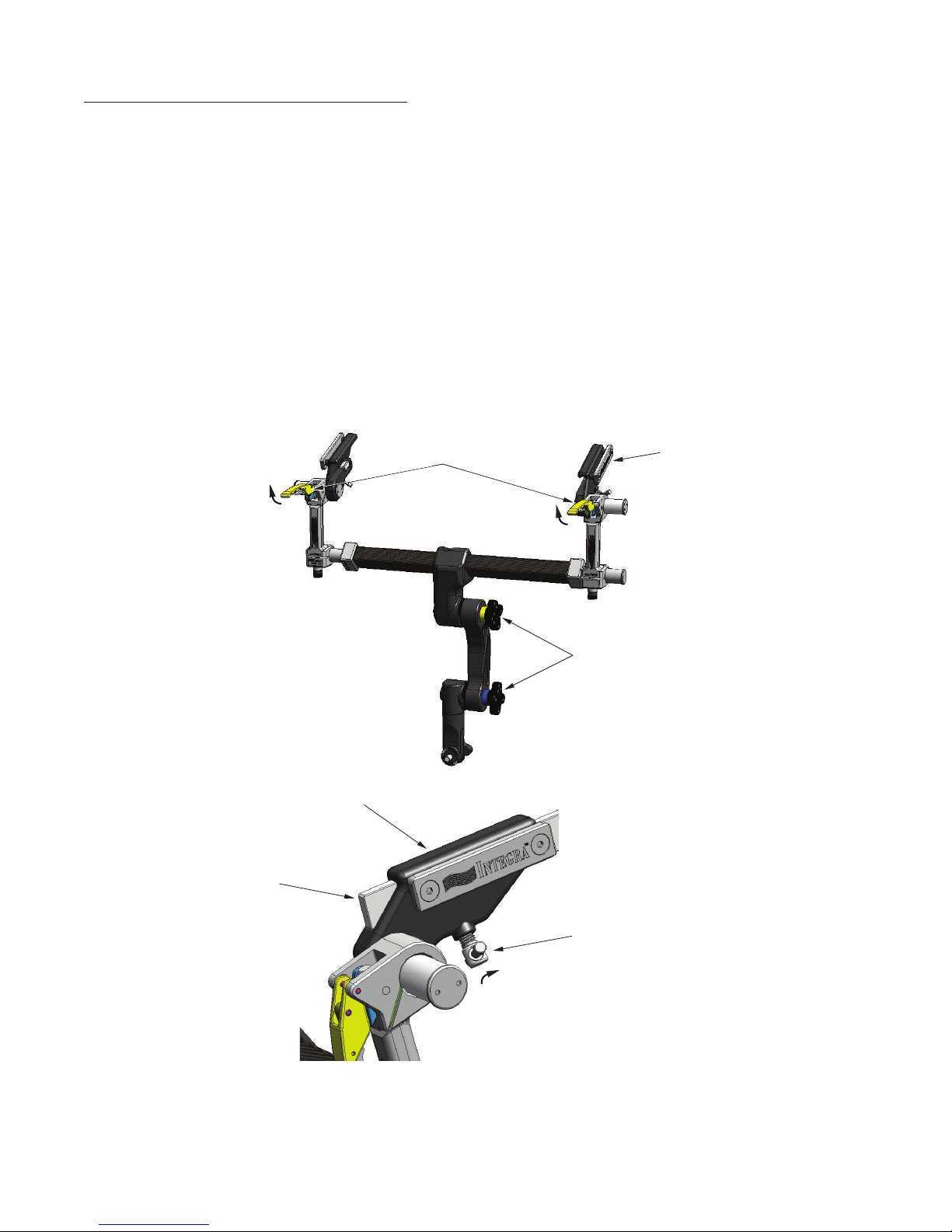
The MAYFIELD Innity XR2 Base Unit (A2079) includes:
(1) MAYFIELD XR2 Base Unit
(2) MAYFIELD XR2 Link Arm Assembly 437A2222
(3) MAYFIELD XR2 Swivel Adaptor 437A2400
Set-up Instructions:
3
1
2
1. Yoke (Yellow tip to Link Arm Locking Knob with Yellow Sleeve
2. Link Arm Assembly
3. Swivel Adaptor (Blue tip to Link Arm Knob with Blue Sleeve)
Figure 2 Base Unit Set-up
Page 4
Page 7

Attachment to Operating Room Table
1. Open Base Unit Locking Levers.
2. Loosen knobs on link arm assembly.
3. Grasp auxiliary side rails on the side rail brackets and carefully place unit on the table’s side
rails.
4. Align Base Unit with the operating table side rails and slide on.
5. Ensure operating table side rails protrude fully through the Base Unit auxiliary rails and
lock into place by tightening the side rail bracket locking knobs.
NOTE: For best alignment results, ensure the operating table side rails protrude evenly on
both sides of the Side Rail Brackets.
Side Rail
Bracket
Operating
Table
Side Rail
Open Locking Levers
Side
Rail
Brackets
Loosen
Link Arm
Knobs
Figure 3 Mounting Base Unit to Operating Table
Tighten Side
Rail Locking
Knobs
Page 5
Page 8
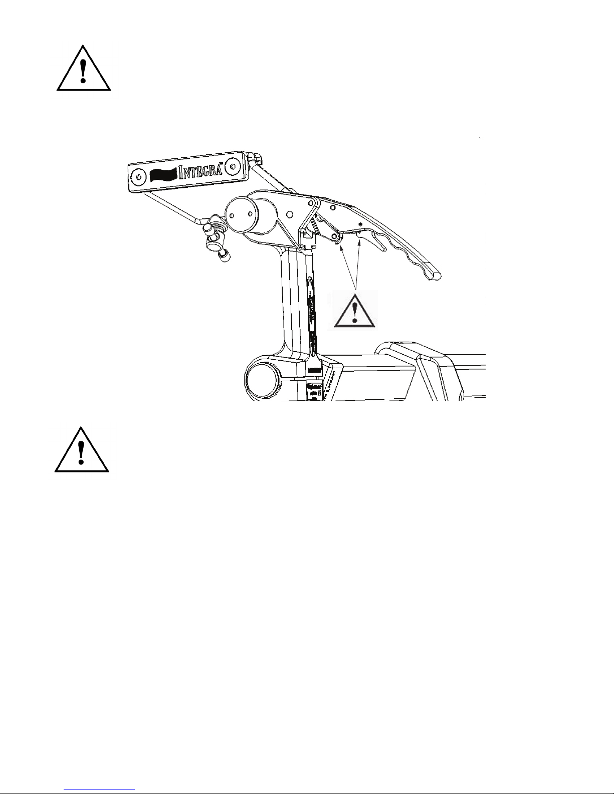
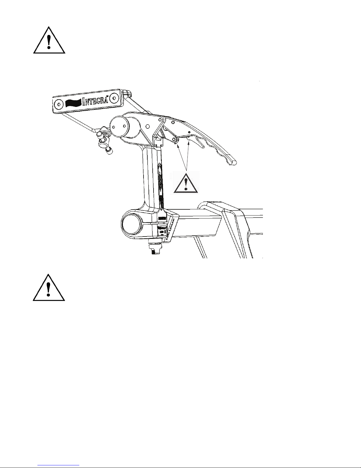
CAUTION: Keep ngers clear of hinge points when closing the Base Unit
Locking Levers. See Figure 4 below. It is recommended that the levers be closed using
the palm of the hand.
Figure 4 Locking Mechanism
CAUTION: Always be sure the Locking mechanisms are secure after
completing table adjustments. Verify that the Locking Lever is secure by
conrming that the Latch is engaged.
Page 6
Page 9
Attachment of The Skull Clamp to The Base Unit
CAUTION!
Once the skull clamp is applied to the patient’s skull, the surgeon will maneuver the patient to the
surgical position that is required for the procedure. With the patient in this position, the
surgeon will hold the patient’s head and the skull clamp and request that the components for the
base unit be brought up for attachment.
1. The base unit should be brought up for attachment to the skull clamp. The mounting
screw of the large starburst on the swivel adaptor should be inserted into the large
starburst of the skull clamp and turned clockwise and tightened. Care should be taken to
maintain the position of the patient’s head as requested by the surgeon.
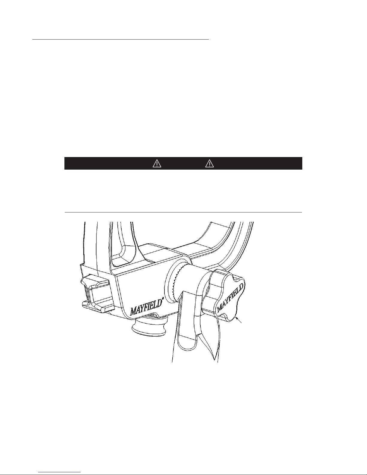
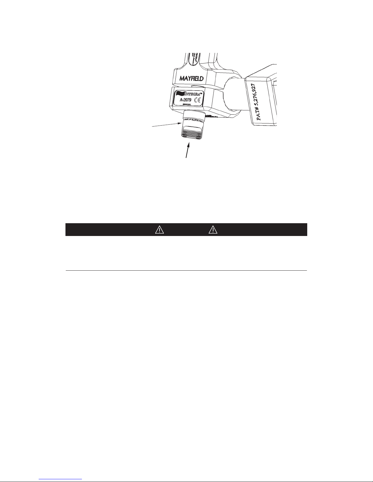
2. Securely fasten the skull clamp to the MAYFIELD base unit by attachment to the Swivel
Adaptor. Close Locking Levers. Turn clockwise all of the Locking Knobs of the other
components of the base unit making certain all starburst teeth are fully meshed (where
applicable) on all joints of the base unit after adjustments are complete.
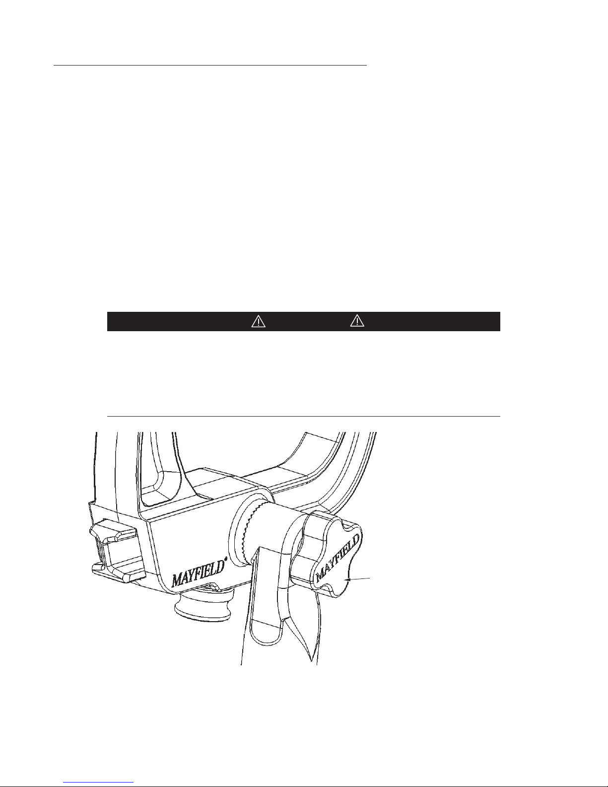
Before fully tightening, always be certain that the starburst teeth of the Swivel
Adaptor and other starburst ttings are the same size and properly mesh.
Failure to do so may damage ttings. Figure 5 shows a typical starburst
connection and proper meshing of teeth.
Skull Clamp/Headrest
locking knob
of the Swivel
Adaptor
Figure 5 Attachment of Skull Clamp
Page 7
Page 10
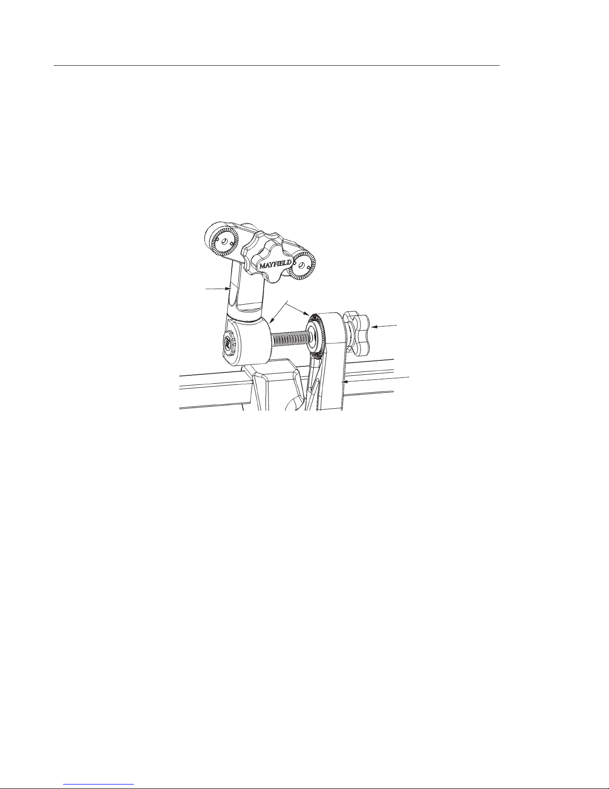
Attachment of Accessories (A2111 Tri-Star Swivel Adaptor)
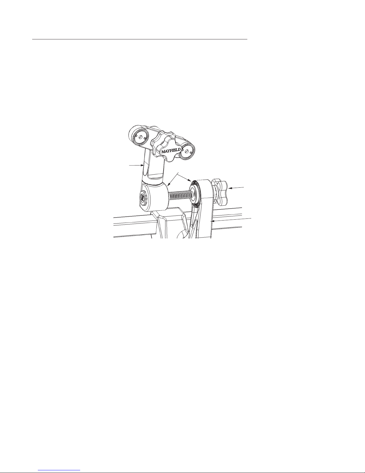
1. Position base unit Swivel Adaptor to desired position.
2. Insert the XR2 TriStar Swivel Adaptor retaining screw into the Link Arm Locking Knob and
rotate knob clockwise.
3. When the XR2 TriStar Swivel Adaptor is set to the desired position, engage starburst teeth
and turn the Link Arm Locking Knob clockwise to secure.
NOTE: Refer to the Tri-Star Swivel Adaptor Instruction For Use manual for proper use and
care.
XR2 TriStar
Swivel
Adaptor
Starburst Teeth
Figure 6 Mounting XR2 Tri-Star Swivel Adaptor
Link
Arm
Locking
Knob
Link
Arm
Page 8
Page 11

Cleaning of the MAYFIELD Innity XR2 Base Unit
WARNING!
CAUTION!
Do Not Steam Sterilize! The carbon Fiber material and plastic components
may be damaged by heat.
Following these steps is recommended:
1. Remove base unit from operating table support rails.
2. Remove Swivel Adaptor, and Link Arm Assembly from base unit
3. The Innity XR2 Base Unit should be thoroughly cleaned after each use. Scrub each
component with a soft brush and use only a pH-neutral detergent. Clean thoroughly to
remove any traces of blood and/or debris and to prevent such blood or debris from
interfering with function or movement. Rinse thoroughly with clean water.
4. Dry all components with a soft dry towel.
5. After components are totally dry, re-assemble the components. Unit is ready for next use.
Optional Automatic Wash Cycle:
Any deviation from this guideline could result in damage to equipment as well
as improper cleaning results. Parameters given below must be followed exactly
in order to assure proper cleaning and avoid damage to the equipment.
• Disassemble the device as indicated in section Cleaning of the MAYFIELD Innity XR2
Base Unit.
• Rinse components under warm tap water prior to placing in washer.
• Arrange device in a way to avoid contact between components.
• Select instrument cycle and ensure proper programming.
Page 9
Page 12

Table 1 Instrument Cycle
Water
Phase
Pre-Wash 1
Enzyme Wash
Wash 1
Rinse 1
Thermal Rinse**
Time in minutes
04:00
04:00
10:00
00:30
02:00
Temperature
Cold tap H
Hot tap H
Hot tap H
82.2° C
* Hot Tap water not to exceed 82.2C
** Optional phase for disinfection of components
Table 1 Instrument Cycle
60° C
2O
2O*
2O*
Detergent type &
Concentration
N/A
Endozime® AW
Triple plus w/
A.P.A., 1:128 ratio
Renu-Klenz®,
1:256 ratio
N/A
N/A
• Remove from washer and dry completely if needed.
• Inspect all components to ensure there is no visible organic debris or residue from
cleaning agent. Repeat process if any visible debris or residue is detected.
Disinfection
Further disinfection of device components may be achieved using one of the following methods.
Method 1: Chemical
• With device cleaned and still disassembled, wipe all surfaces with sterile gauze moistened
with 70% Isopropyl Alcohol (IPA). Be sure to achieve even coverage on all surfaces.
• Assure the device stays wet with the 70% IPA for a minimum of 10 minutes.
• Dry the device with a sterile lint free cloth or blow dry with ltered pressurized air.
Method 2: Thermal Rinse
• A Thermal Disinfection phase maybe added after the rinse cycle as indicated in table 1.
Page 10
Page 13

Maintenance and Care:
The Innity XR2 Base Unit should be returned to its storage case after each use.
NOTE: Ensure all components have completely dried after cleaning before returning to case.
If unit is dropped or mishandled, it should be inspected for damage.
(REF Inspection section of this instruction manual) If damage occurs, do not
use; return the complete device immediately to Integra LifeSciences
for inspection.
CAUTION!
Inspection of Components
A routine inspection of the components of the MAYFIELD Innity XR2 Base Unit should be made
before each and every procedure to assist in keeping it in good functional condition and to avoid
problems the day of surgery. This check should include the following:
1. Check to see that all the components of the base unit are available for assembly. Use the
Inspection section of this Instruction Manual for a complete list of components. ALL
components must be available and ready for assembly or the base unit should not be
used.
2. Check the adjustment of the base locking handles by following these steps.
a. Attach the base unit to an OR table and lock to the side rails.
b. Raise the Crossbar to be even with the top of the OR table, locking the handles.
c. With your hands on either ends of the Crossbar, push down on the Crossbar attempting
to move it. If with minimal force, the Crossbar moves, adjustment to increase the
locking power of the Locking Handles should be made as outlined in this manual.
d. If the handles are too hard to close, adjustment to decrease the locking power of the
Locking Handles should be made as outlined in this manual.
3. With the Locking Handles unlocked and all the components attached but loose, raise and
lower the base unit, rotating all joints. All should freely rotate without any “ratcheting”
noise (starburst teeth hitting together as rotated). If this ratcheting noise is heard, loosen
the joint that is causing the noise.
4. Check the other components for function
a. Again, with the base unit Crossbar raised to be level with the top of the OR table, lock
the locking handles.
b. Lock the link arm locking knobs
c. Verify that all starbursts are fully engaged and locked
d. With these knobs locked, the total base unit should be locked into place and no
movement should be seen.
Page 11
Page 14
e. Exert force to each component to detect any movement. There should be no lateral or
Locking Lever
rotational movement with the knobs of the Link Arm totally tightened. If movement is
seen, re-tighten the knobs and check again.
5. Perform visual check of all components (Start at one side of the base unit and
systematically review each component as you make your way to the other side to assure
that you do not miss a component)
a. Check all connections to be free of debris that might impair the function of that
component or the one that connects to that component.
b. Examine all components for cracks on all surfaces.
c. Check the side rails to be securely fastened to the Side Rail Brackets
d. Check that the Shock Cushion is present and in proper position on both Locking Handle
assemblies.
e. Slide the yoke from side to side on the crossbar to make certain that the surface is
smooth and free of debris or anything that would impede its movement.
Base Locking Lever Handle Adjustment Procedure
Periodically it is necessary to adjust the tension in the Base Handle Assemblies to compensate for
changes due to normal use.
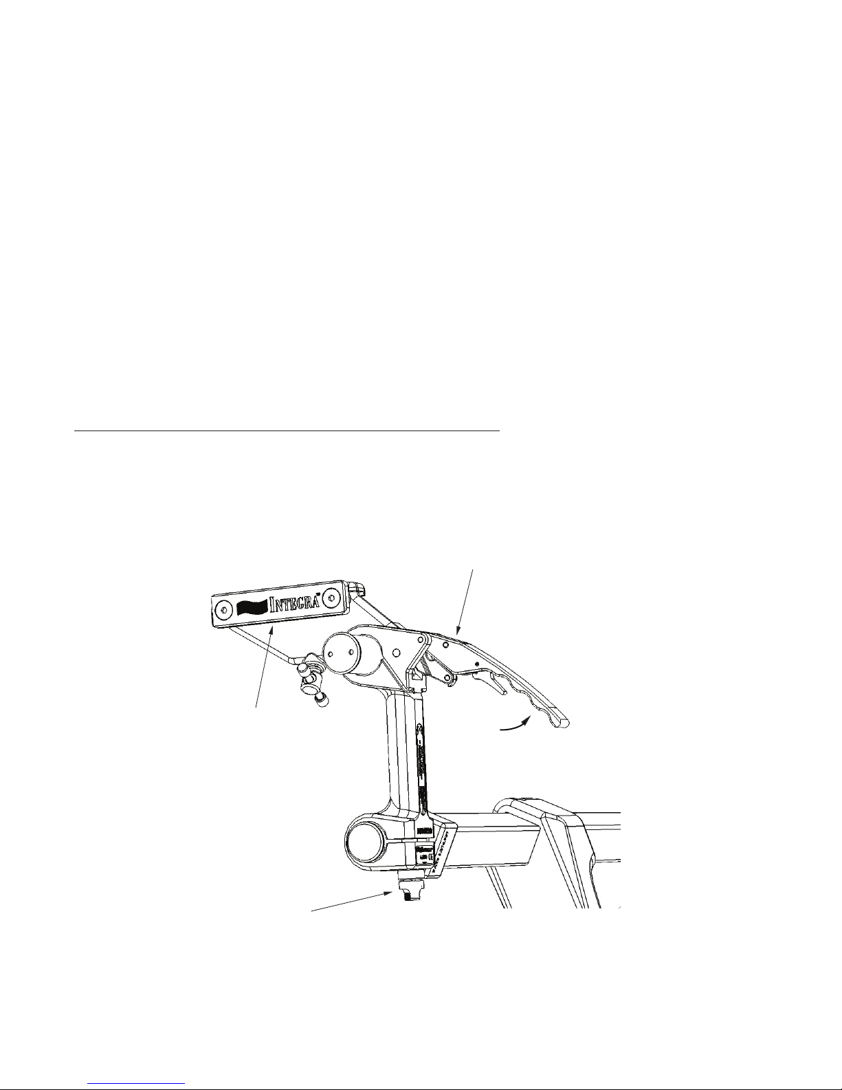
1. Open Locking Lever. For safety, the tension Adjustment Knob is not adjustable while the
Locking Lever is closed.
Auxiliary Side Rail
Locking
Lever
Opened
Tension
Adjustment Knob
Figure 7 Opening Locking Lever
Page 12
Page 15
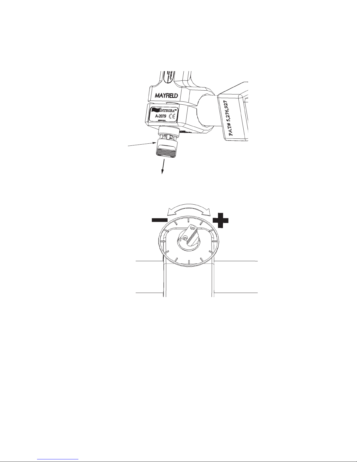
2. Grasp the Adjustment Knob and pull it away from the Locking Bracket to unlock.
3. Holding the Adjustment Knob in its unlocked position, rotate it in the desired direction to
adjust tension. Clockwise (+ plus) direction to increase tension, or Counterclockwise
(- minus) direction to decrease tension.
Adjustment Knob
Adjustment Knob Pulled to
the Unlocked Position
Decrease Locking
Lever Tension
Figure 8 Adjustment Knob
Increase Locking
Lever Tension
Page 13
Page 16
4. Return the Adjustment Knob to its locked position by releasing it and rotating it to the
CAUTION!
nearest seated locking position.
Adjustment Knob
Adjustment Knob Retracted
to the Locked Position
Figure 9 Adjustment Knob in Locked Position
5. Test the operation of the handle. With the Locking Lever fully opened, the Locking Bracket
should rotate freely. With the Locking Lever closed, the Locking Bracket should not rotate.
NOTE: Once the desired setting is achieved conrm the Adjustment Knob is in the locked,
seated position.
It is possible to adjust the handle to the point that the Locking Lever requires
excessive force to close. Do not exert excessive force as this may result in
damage to the device if the lever is forced closed.
Page 14
Page 17

Integra Standard Warranty
INTEGRA LIFESCIENCES CORPORATION (“INTEGRA”) warrants to the original purchaser only that
each new INTEGRA Mayeld® product is free from manufacturing defects in material and
workmanship under normal use and service for a period of one year (except as otherwise
expressly provided as to accessory items) from the date of delivery by INTEGRA to the rst
purchaser, but in no event beyond the expiration date stated on any product labeling.
• Surgical instruments are guaranteed to be free from defects in material and workmanship
when maintained and cleaned properly and used normally for their intended purpose.
• Any covered product that is placed by INTEGRA under a lease, rental or installment
purchase agreement and that requires repair service during the term of such placement
agreement shall be repaired in accordance with the terms of such agreement.
If any covered defect occurs during the warranty period or term of such placement agreement,
the purchaser should communicate directly with INTEGRA’s home oce. If purchaser seeks to
invoke the terms of this warranty, the product must be returned to INTEGRA at its home oce.
The defective product should be returned promptly, properly packaged and postage prepaid.
Loss or damage in return shipment to INTEGRA shall be at CUSTOMER’s risk. INTEGRA’s sole
responsibility under this warranty shall be repair or replacement, at INTEGRA’s sole discretion at
INTEGRA’s expense, subject to the terms of this warranty and applicable agreements.
IN NO EVENT SHALL INTEGRA BE LIABLE FOR ANY INCIDENTAL, INDIRECT, CONSEQUENTIAL OR
PUNITIVE DAMAGES IN CONNECTION WITH THE ACQUISITION OR USE OF ANY INTEGRA
PRODUCT. Further, this warranty shall not apply to, and INTEGRA shall not be responsible for, any
loss arising in connection with the purchase or use of any INTEGRA product that has been
repaired by anyone other than an authorized INTEGRA service representative or altered in any
way so as, in INTEGRA’s judgment, to aect its stability or reliability, or which has been subject to
misuse, negligence or accident, or which has been used otherwise than in accordance with the
instructions furnished by INTEGRA. THIS LIMITED WARRANTY IS EXCLUSIVE AND IN LIEU OF ALL
OTHER WARRANTIES, EXPRESS OR IMPLIED, AND OF ALL OTHER OBLIGATIONS OR LIABILITIES
ON INTEGRA’S PART, AND INTEGRA NEITHER ASSUMES NOR AUTHORIZES ANY REPRESENTATIVE
OR OTHER PERSON TO ASSUME FOR IT ANY OTHER LIABILITY IN CONNECTION WITH INTEGRA’S
PRODUCTS.
INTEGRA DISCLAIMS ALL OTHER WARRANTIES, EXPRESS OR IMPLIED INCLUDING ANY IMPLIED
WARRANTY OF MERCHANTABILITY OR OF FITNESS FOR A PARTICULAR PURPOSE OR APPLICATION
OR WARRANTY OF QUALITY AS WELL AS ANY EXPRESS OR IMPLIED WARRANTY TO PATIENTS. No
warranty or guarantee may be created by any act or statement nor may this Standard Warranty be
modied in any way, except as a result of a writing signed by an ocer of INTEGRA. These
limitations on the creation or modication of this warranty may not be waived or modied orally
or by any conduct.
Page 15
Page 18

Service and Repair
For service and repairs outside the United States, contact your local authorized Integra
representative.
Within the United States, send all instruments for service or repair to:
Integra LifeSciences Corporation
4900 Charlemar Drive, Building A
Cincinnati, Ohio 45227
(Always include the purchase order number and a written description of the problem)
Or phone: 888-444-2114
Publication Number 451A2079 Rev A
Page 16
Page 19
IMPORTANTE
Por favor, léase
MAYFIELD®
Innity XR2 Base
( #A2079)
Manual de instrucciones
Sólo bajo prescripción médica
Integra LifeSciences Corporation
4900 Charlemar Drive, Building A, Cincinnati, OH 45227, EE. UU.
Tel.: +1-513-533-7979 Fax: +1-513-271-1915
www.Integra-LS.com
Integra NeuroSciences, Limited
Newbury Road, Andover, Hampshire SP10 4 DR, Inglaterra
Tel.: +44 (0) 1264 345 700 Fax: +44 (0) 1264 332 113
MAYFIELD® es una marca registrada de SM USA, Inc.
y es utilizado por INTEGRA LIFESCIENCES Corporation bajo licencia.
Page 20
Signicado de los símbolos utilizados en este manual - ESPAÑOL
PRECAUCIÓN!
Peligros que podrían causar daños materiales o al equipo.
Peligros que podrían ocasionar lesiones personales graves o la muerte.
Atención, consulte los documentos adjuntos.
Conforme con la Directiva Europea sobre Dispositivos Médicos (MDD).
Lugar de fabricación.
Representante europeo.
Consulte el Manual de instrucciones.
Sólo bajo prescripción médica
Precaución: La ley federal (EE. UU.) restringe la venta de este dispositivo a médicos
colegiados o por prescripción facultativa.
REF
Número de catálogo del product
Page 21
Inspección
Inspeccione siempre los instrumentos antes y después de su uso. Si un componente parece
dañado y/o parece que no funciona correctamente, no lo use y envíe de inmediato el
instrumento a Integra LifeSciences, Cincinnati, Ohio o a un centro de reparación autorizado de
Integra para su evaluación, reparación o sustitución.
1
10
2
3
8
5
9
3
6
7
11
4
1. Botón de bloqueo del dispositivo de jación craneal/reposacabezas
2. Adaptador del pivote giratorio
3. Botones de bloqueo del brazo de enganche
4. Horquilla
5. Barra transversal
6. Asa de la base
7. Abrazadera del raíl lateral
8. Palanca de bloqueo
9. Botón de ajuste del asa de la base
10. Raíl lateral auxiliar
11. Botón de bloqueo de la abrazadera del raíl lateral
Figura 1 Componentes de la base Innity XR2 A2079
Página 1
Page 22

Indicación de uso
La base Innity XR2 está prevista para soportar a un paciente durante los procedimientos de
examen de diagnóstico y/o quirúrgicos en los que es necesario un soporte rígido entre la camilla
del quirófano y el reposacabezas, o un dispositivo de jación craneal, se precisa libertad
posicional y se utilizarán diversas modalidades de obtención de imágenes por rayos X.
La no lectura y el incumplimiento de las instrucciones incluidas en el prospecto
de este producto pueden ocasionar lesiones graves al paciente.
No esterilice con vapor; los componentes pueden dañarse con el calor elevado,
lo que provocaría el daño del dispositivo y un rendimiento reducido.
El reposacabezas o el dispositivo de jación craneal deben sujetarse
rmemente a la base. Si no se aprietan por completo todas las porciones de
ajuste de este dispositivo o de otro similar, se pueden provocar lesiones graves
al paciente.
El usuario debe comprobar que todas las conexiones roscadas estén seguras
y que las conexiones en estrella se hayan engranado (cuando corresponda)
después de completar los ajustes. El incumplimiento de esta medida puede
provocar lesiones graves al paciente.
PRECAUCIÓN!
Compruebe siempre que la base esté bien jada a la camilla del quirófano.
No se debe usar la base si el dispositivo parece estar dañado o funciona
incorrectamente.
Apretar en exceso los tornillos de ajuste de los mecanismos puede provocar
daños a la unidad.
Extender en exceso o sobrecargar la base puede provocar movimientos
imprevistos, acortar la vida útil del producto y/o dañar la unidad.
No altere la construcción de este dispositivo dado que podría provocar lesiones
graves al paciente.
Página 2
Page 23

Descripción
La base MAYFIELD Innity XR2 está diseñada para proporcionar jación desde la camilla del quirófano a los dispositivos de jación craneal MAYFIELD para jación esquelética rígida o a los reposacabezas de herradura MAYFIELD para procedimientos en los que solamente se necesita soporte y
no jación rígida. La base XR2 está diseñada para el posicionamiento del paciente en posición de
decúbito prono, lateral o decúbito supino para jación a un dispositivo de jación craneal o a un
reposacabezas de herradura. Se ja a los raíles laterales de la camilla del quirófano con un ajuste
fácil para camillas de una gran variedad de anchos.
La base Innity XR2 es apropiada para la angiografía digital por sustracción (DSA), la uoroscopia
y los distintos métodos de diagnóstico por imágenes TC.
Los componentes de la base XR2 están codicados por colores para un fácil ensamblaje para el
uso y un fácil desmontaje para la limpieza y el almacenamiento. Se proporciona una funda de
almacenamiento por separado con la base para guardarla con seguridad entre procedimientos y
para usarla al enviar el producto a una reparación o trabajo de mantenimiento.
Se encuentra disponible un adaptador del pivote giratorio Tri-Star (A2111) por separado y opcional para su uso con la base XR2 cuando en los procedimientos se utilicen sistemas de cirugía
guiados por imágenes (IGS). El adaptador del pivote giratorio Tri-Star proporciona dos conexiones
en estrella adicionales para jar el equipo IGS auxiliar. Consulte el Manual de instrucciones por
separado del A2111 para más información.
La base Innity XR2 está diseñada para su uso con los siguientes equipos:
Dispositivo de jación craneal MAYFIELD Innity XR2 A2114
Dispositivo de jación craneal radiotransparente MAYFIELD 2000 A2002
Adaptador del pivote giratorio Tri-Star MAYFIELD Innity XR2 A2111
Dispositivo de jación craneal radiotransparente MAYFIELD A1058
Reposacabezas de herradura radiotransparente MAYFIELD A2010
Reposacabezas de herradura radiotransparente pediátrico MAYFIELD A2011
NOTA: Se recomienda no usar los productos y accesorios MAYFIELD con equipos de
estabilización de otros fabricantes.
Página 3
Page 24

La base MAYFIELD Innity XR2 (A2079) incluye:
tremo azul al botón del brazo de enganche con manguito azul)
(1) Base MAYFIELD XR2
(2) Unidad de brazo de enganche MAYFIELD XR2 437A2222
(3) Adaptador del pivote giratorio MAYFIELD XR2 437A2400
Instrucciones de montaje:
3
1
2
1. Horquilla (Extremo amarillo al botón de bloqueo del brazo de enganche con manguito amarillo)
2. Unidad de brazo de enganche
3. Adaptador del pivote giratorio (Ex
Figura 2 Montaje de la base
Página 4
Page 25
Fijación a la camilla del quirófano
1. Abra las palancas de bloqueo de la base.
2. Aoje los botones en la unidad de brazo de enganche.
3. Sujete los raíles laterales auxiliares en las abrazaderas del raíl lateral y coloque con cuidado
la unidad en los raíles laterales de la camilla.
4. Alinee la base con los raíles laterales de la camilla del quirófano y deslícela.
5. Asegúrese de que los raíles laterales de la camilla del quirófano sobresalgan por completo
a través de los raíles auxiliares de la base y bloquéelos en su sitio apretando los botones de
bloqueo de las abrazaderas de los raíles laterales.
NOTA: Para una mejor alineación, asegúrese de que los raíles laterales de la camilla del
quirófano sobresalgan uniformemente por ambos lados de las abrazaderas del raíl lateral.
Abrazadera del
raíl lateral
Raíl lateral de la camilla
del quirófano
Abra las palancas de bloqueo
Abrazaderas del
raíl lateral
Botones del brazo de
enganche aojados
Figura 3 Montaje de la base en la camilla del quirófano
Apriete los botones de
bloqueo del raíl lateral
Página 5
Page 26
PRECAUCIÓN: Mantenga los dedos fuera de los puntos de bisagra cuando cierre las
palancas de bloqueo de la base. Ver gura 4 más adelante. Se recomienda cerrar las
palancas usando la palma de la mano.
Figura 4 Mecanismo de bloqueo
PRECAUCIÓN: Asegúrese siempre de jar los mecanismos de bloqueo después de
completar los ajustes de la camilla. Compruebe que la palanca de bloqueo esté ja
conrmando que el seguro esté puesto.
Página 6
Page 27
Fijación del dispositivo de jación craneal a la base
Una vez aplicado el dispositivo de jación craneal al cráneo del paciente, el cirujano maniobrará
al paciente para colocarle en la posición quirúrgica que requiera la intervención. Con el paciente
en esta posición, el cirujano sujetará la cabeza del paciente y el dispositivo de jación craneal y
pedirá que le acerquen los componentes de la base para jarla.
1. La base deberá llevarse a la altura adecuada para ajustarla al dispositivo de jación
craneal. El tornillo de montaje de la conexión mayor en estrella situada sobre el adaptador
del pivote giratorio deberá introducirse en la conexión mayor en estrella del dispositivo
de jación craneal haciéndolo girar en la dirección de las agujas del reloj y apretándolo.
Se debe procurar que la posición de la cabeza del paciente se mantenga de acuerdo a lo
solicitado por el cirujano.
2. Sujete rmemente el dispositivo de jación craneal a la base MAYFIELD jando el
adaptador del pivote giratorio. Cierre las palancas de bloqueo. Gire todos los botones de
bloqueo de los demás componentes de la base en la dirección de las agujas del reloj,
comprobando que todos los dientes de la conexión en estrella estén completamente
engranados (cuando proceda) en todas las juntas de la base, una vez nalizados
los ajustes.
PRECAUCIÓN!
Antes de apretar a fondo, compruebe siempre que los dientes de la conexión
en estrella del adaptador del pivote giratorio y las piezas de acople son del
mismo tamaño y engranan adecuadamente. Si no se comprueba esto, podrían
dañarse las piezas. La gura 5 muestra una conexión típica en estrella y el
adecuado engranaje de los dientes.
Botón de ajuste del dispositivo
de jación craneal/reposacabezas del
adaptador del pivote giratorio.
Figura 5 Fijación del dispositivo de jación craneal
Página 7
Page 28
Fijación de los accesorios (Adaptador del pivote giratorio Tri-Star A2111)
1. Colocación del adaptador del pivote giratorio de la base en la posición deseada.
2. Inserte el tornillo de retención del adaptador del pivote giratorio XR2 Tri-Star en el botón
de bloqueo del brazo de enganche y gire el botón en la dirección de las agujas del reloj.
3. Cuando el adaptador del pivote giratorio XR2 Tri-Star se coloque en la posición deseada,
acople los dientes de la conexión en estrella y gire el botón de bloqueo del brazo de
enganche en la dirección de las agujas del reloj para asegurarlo.
NOTA: Consulte las Instrucciones de uso del adaptador del pivote giratorio Tri-Star para un
uso y cuidado adecuados.
Adaptador del pivote
giratorio XR2 Tri-Star
Dientes de la conexión en estrella
Botón de bloqueo del
brazo de enganche
Brazo de
enganche
Adaptador del pivote giratorio XR2 Tri-Star
Página 8
Page 29

Limpieza de la base MAYFIELD Innity XR2
¡No esterilice con vapor! El material de bra de carbono y los componentes de
plástico pueden dañarse con el calor
Se recomienda seguir los siguientes pasos:
1. Retire la base de los raíles de soporte de la camilla del quirófano.
2. Retire el adaptador del pivote giratorio y la unidad del brazo de enganche de la base
3. La base Innity XR2 debe limpiarse minuciosamente después de cada uso. Frote cada
componente con un cepillo blando y use solamente detergente con pH neutro. Limpie a
conciencia para quitar y los rastros de la sangre y/o de los escombros y para evitar que tal
sangre o escombros interera con la función o el movimiento.
4. Seque todos los componentes con una toalla suave y seca.
5. Una vez que los componentes estén completamente secos, vuelva a montarlos. La unidad
está lista para el próximo uso.
Ciclo de lavado automático opcional:
PRECAUCIÓN!
Cualquier desviación de estas pautas podría dañar el equipo y dar lugar a una
limpieza inadecuada. Los parámetros que se indican a continuación deberán
seguirse estrictamente para garantizar una limpieza adecuada y evitar que el
equipo resulte dañado.
• Desmonte el dispositivo tal y como se indicó en la sección Limpieza de la base MAY-
FIELD Innity XR2.
• Enjuague los componentes con agua corriente tibia antes de colocarlos en la lavadora.
• Coloque los componentes del dispositivo de forma que no entren en contacto unos con
otros.
• Seleccione el ciclo para instrumental y verique que la programación es la correcta.
Página 9
Page 30

Tabla 1 Ciclo para instrumental
Fase
Prelavado
Lavado
enzimático
Lavado1
Enjuague 1
Enjuague
térmico**
*El agua corriente caliente no debe superar los 82,2º C
** Fase Opcional para la desinfección de los componentes
Tiempo en
minutos
04:00
04:00
10:00
00:30
02:00
Tabla 1 Ciclo para instrumental
Temperatura del
agua
Agua corriente
fría
Agua corriente
caliente*
60° C
Agua corriente
caliente*
82,2° C
Tipo de temperatura y
concentración
N/A
Endozime® AW Triple
plus c/ A.P.A.,
proporción 1:128
Renu-Klenz®,
proporción 1:256 ratio
N/A
N/A
• Retire de la lavadora y seque completamente si es necesario.
• Inspeccione todos los componentes para comprobar que no queda ningún resto
orgánico ni residuo de alguno de los productos de limpieza. Repita el proceso si se detecta algún resto de suciedad.
Desinfección
Se puede lograr una mejor desinfección de los componentes del dispositivo usando alguno de
los siguientes métodos.
Método 1: Químico
• Con el dispositivo limpio y todavía desmontado, limpie todas las supercies con una gasa
estéril humedecida con alcohol isopropílico (IPA) al 70%. Asegúrese de aplicarlo
uniformemente sobre todas las supercies.
• Asegúrese de que el dispositivo se mantiene humedecido con IPA al 70% al menos durante 10 minutos.
• Seque el dispositivo con un paño estéril que no desprenda pelusa o séquelo con un
secador de aire comprimido ltrado.
Método 2: Lavado térmico
• Se puede añadir una fase de desinfección térmica después del ciclo de enjuague tal y
como se indica en la tabla 1.
Página 10
Page 31

Mantenimiento y cuidado:
La base Innity XR2 debe volverse a colocar en su funda de almacenamiento después de cada
uso.
NOTA: Asegúrese de que todos los componentes se hayan secado por completo después de la
limpieza antes de volverlos a colocar en la funda.
PRECAUCIÓN!
Si la unidad se cae o se manipula indebidamente, debe ser inspeccionada en
busca de daños (REF. Sección Inspección de este manual de instrucciones). Si
se daña no utilice el producto, devuelva todo el dispositivo inmediatamente a
Integra LifeSciences para su inspección.
Inspección de los componentes
Se debe llevar a cabo una inspección de rutina de los componentes de la base MAYFIELD Innity XR2 antes de cada procedimiento para ayudar a mantener el aparato en buenas condiciones
de funcionamiento y para evitar problemas el día de la intervención quirúrgica. Esta vericación
deberá incluir lo siguiente:
1. Compruebe que todos los componentes de la base estén disponibles para su ensamblaje.
Utilice la sección Inspección de este manual de instrucciones para obtener una lista
completa de los componentes. TODOS los componentes deben estar disponibles y listos
para su ensamblaje de lo contrario no se debe usar la base.
2. Compruebe el ajuste de las asas de bloqueo de la base del siguiente modo:
a. Fije la base a una camilla del quirófano y bloquee los raíles laterales.
b. Eleve la barra transversal para que esté al ras con la parte superior de la camilla del
quirófano, bloqueando las asas.
c. Con las manos en ambos extremos de la barra transversal, empuje hacia abajo la barra
transversal intentando moverla. Si con una fuerza mínima, la barra transversal se mueve,
se deben realizar ajustes, tal y como se describe en este manual, para aumentar la
intensidad del bloqueo de las asas de bloqueo.
d. Si las asas son demasiado difíciles de cerrar, se deben realizar ajustes, tal y como se
describe en este manual, para reducir la intensidad del bloqueo de las asas de bloqueo.
3. Con las asas de bloqueo desbloqueadas y todos los componentes jados pero sueltos,
eleve y descienda la base, rotando todas las articulaciones. Todo debería rotar libremente
sin ningún ruido de “carraca” (los dientes de la conexión en estrella encajando mientras
rotan). Si se escucha un ruido de carraca, aoje la articulación que provoca el ruido.
4. Compruebe el funcionamiento de los otros componentes.
a. De nuevo, con la barra transversal de la base elevada para estar al ras con la parte
superior de la camilla del quirófano, bloquee las asas de bloqueo.
b. Proceda a bloquear los botones de bloqueo del brazo de enganche
c. Compruebe que todas las conexiones en estrella estén totalmente acopladas y
bloqueadas
Página 11
Page 32

d. Con estos botones bloqueados, la totalidad de la base debería estar bloqueada en su
Palanca de bloqueo
sitio y no se debería apreciar ningún movimiento.
e. Aplique fuerza sobre cada componente para detectar cualquier movimiento. No debería
existir ningún movimiento lateral ni rotacional con los botones del brazo de enganche
totalmente apretados. Si se aprecia movimiento, vuelva a apretar los botones y compruebe de nuevo.
5. Compruebe visualmente todos los componentes (empiece por un lado de la base y revise
sistemáticamente cada componente a medida que avanza hacia el otro lado, para
garantizar que no pasa por alto ningún componente).
a. Compruebe que todas las conexiones están libres de residuos que podrían afectar al
funcionamiento de ese componente o del que se conecta a ese componente.
b. Revise todos los componentes en busca de grietas en todas las supercies.
c. Compruebe que los raíles laterales estén rmemente ajustados a las abrazaderas de los
raíles laterales
d. Compruebe que la almohadilla de impacto esté colocada en posición correcta en
ambas unidades de asa de bloqueo.
e. Deslice la horquilla de lado a lado en la barra transversal para asegurar que la supercie
sea suave y esté libre de residuos o de cualquier cosa que pudiese impedir su
movimiento.
Procedimiento de ajuste del asa de la palanca de bloqueo de la base
Es necesario ajustar la tensión de las unidades de asa de la base periódicamente para compensar
los cambios debidos al uso normal.
1. Abra la palanca de bloqueo. Por seguridad, el botón de ajuste de la tensión no es ajustable
mientras la palanca de bloqueo esté cerrada.
Raíl lateral auxiliar
Palanca de
bloqueo
abierta
Tensión Arregio Tirador
Figura 7 Apertura de la palanca de bloqueo
Página 12
Page 33

2. Agarre el botón de ajuste y retírelo de la abrazadera de bloqueo para desbloquear.
3. Sujetando el botón de ajuste en su posición desbloqueada, gírelo en la dirección deseada
para ajustar la tensión. En la dirección de las agujas del reloj (+ más) para aumentar la
tensión, o en la dirección contraria a las agujas del reloj (- menos) para reducir la tensión.
Botón de ajuste
Botón de ajuste en
posición de desbloqueo
Reduce la tensión de
la palanca de bloqueo
Aumenta la tensión de
la palanca de bloqueo
Figura 8 Botón de ajuste
Página 13
Page 34

4. Vuelva a colocar el botón de ajuste en su posición de bloqueo soltándolo y girándolo
hasta la posición de bloqueo asentada más cercana.
Botón de ajuste
Botón de ajuste retraído a la
posición de bloqueo
Figura 9 Botón de ajuste en la posición de bloqueo
5. Compruebe el funcionamiento del asa. Con la palanca de bloqueo totalmente abierta, la
abrazadera de bloqueo debería girar libremente. Con la palanca de bloqueo cerrada, la
abrazadera de bloqueo no debería girar.
NOTA: Una vez que se logre el ajuste deseado, conrme que el botón de ajuste esté en la
posición de bloqueo asentada.
PRECAUCIÓN!
Es posible ajustar el asa hasta el punto de que la palanca de bloqueo requiera
una fuerza excesiva para cerrarse. No ejerza una fuerza excesiva, el dispositivo
se podría dañar si la palanca se cierra a la fuerza.
Garantía estándar de Integra
INTEGRA LIFESCIENCES CORPORATION (“INTEGRA”) garantiza sólo al comprador original que
cada nuevo producto INTEGRA Mayeld® no presenta defectos de fabricación en el material ni
en su fabricación, bajo un uso normal, y garantiza el mantenimiento durante un período de un
año (excepto en lo dispuesto expresamente para los elementos accesorios) a partir de la fecha de
entrega por parte de INTEGRA al primer comprador, pero en ningún caso más allá de la fecha de
vencimiento que consta en la etiqueta del producto
• Se garantiza que los instrumentos quirúrgicos no presentan defectos de material ni de
fabricación siempre que se sometan a mantenimiento y limpieza correctos, y se usen
normalmente para los nes previstos.
• Cualquier producto cubierto que INTEGRA proporcione bajo un contrato de alquiler,
arrendamiento, nanciación a plazos y que requiera un servicio de reparación durante el
plazo de vigencia de dicho acuerdo deberá ser reparado de conformidad con los términos
de dicho acuerdo.
Página 14
Page 35

Si se observa algún defecto cubierto durante el período de garantía o durante el plazo establecido en el acuerdo de compra, el comprador deberá comunicarlo directamente a las ocinas
centrales de INTEGRA. Si los compradores pretenden recurrir a los términos de esta garantía,
deberán devolver el producto a las ocinas centrales de INTEGRA. El producto defectuoso deberá
ser devuelto a la mayor brevedad, empaquetado adecuadamente y con franqueo prepagado. La
pérdida o el deterioro durante la devolución a INTEGRA será un riesgo a cargo del CLIENTE. La
única responsabilidad de INTEGRA bajo esta garantía será la de reparar o reemplazar el producto,
a la sola discreción de INTEGRA y a sus expensas, sujeto a los términos de esta garantía y a los
acuerdos pertinentes.
BAJO NINGUNA CIRCUNSTANCIA INTEGRA SERÁ RESPONSABLE DE NINGÚN DAÑO INCIDENTAL,
INDIRECTO, RESULTANTE O EXCESIVO EN RELACIÓN CON LA ADQUISICIÓN O USO DE CUALQUIER
PRODUCTO DE INTEGRA. Además, esta garantía no se aplicará a, e INTEGRA no será responsable
de, cualquier pérdida relacionada con la compra o uso de cualquier producto de INTEGRA que
haya sido reparado por cualquier otra persona que no sea el representante de servicio técnico
autorizado por INTEGRA o se haya alterado en alguna forma que, a juicio de INTEGRA, se haya
afectado su estabilidad o abilidad, o haya sido sujeto a uso inadecuado, negligencia o accidente,
o haya sido usado de alguna otra forma a lo acordado en las instrucciones proporcionadas por
INTEGRA. ESTA GARANTÍA LIMITADA ES EXCLUSIVA Y EN LUGAR DE CUALQUIER OTRA GARANTÍA,
EXPRESA O IMPLÍCITA, Y DE CUALQUIER OTRA OBLIGACIÓN O RESPONSABILIDAD POR PARTE DE
INTEGRA, E INTEGRA NI ASUME NI AUTORIZA A NINGÚN REPRESENTANTE U OTRA PERSONA A
ASUMIR EN SU NOMBRE NINGUNA OTRA RESPONSABILIDAD EN CONEXIÓN CON LOS
PRODUCTOS DE INTEGRA.
INTEGRA NIEGA CUALQUIER OTRA GARANTÍA, EXPRESA O IMPLÍCITA, INCLUIDA CUALQUIER
GARANTÍA DE COMERCIALIZACIÓN O IDONEIDAD PARA UN FIN O APLICACIÓN DETERMINADOS,
O LA APLICACIÓN O LA GARANTÍA DE CALIDAD, ASÍ COMO CUALQUIER GARANTÍA EXPRESA O
IMPLÍCITA PARA LOS PACIENTES. No se puede crear ninguna garantía a partir de una ley o declaración ni esta Garantía estándar puede ser modicada en ningún modo, excepto por escrito
rmado por un delegado de INTEGRA. Estas limitaciones en la creación o modicación de esta
garantía pueden ser dispensadas o modicadas de forma oral o por algún otro medio.
Servicio técnico y reparación
Para el mantenimiento o para reparaciones fuera de Estados Unidos, póngase en contacto con el
representante local autorizado de Integra.
En Estados Unidos, envíe todos los instrumentos para su mantenimiento o reparación a:
Integra LifeSciences Corporation
4900 Charlemar Drive, Building A
Cincinnati, Ohio 45227
(Incluya siempre el número de orden de compra y una descripción por escrito del problema)
O llame al teléfono: 888-444-2114
Página 15
Page 36

Número de publicación 451A2079 Rev A
Página 16
Page 37

IMPORTANT
À lire
MAYFIELD®
Innity XR2 Unité de base
( #A2079)
Mode d’emploi
Sur ordonnance uniquement
Integra LifeSciences Corporation
4900 Charlemar Drive, Building A, Cincinnati, OH 45227, États-Unis
Tél. : +1-513-533-7979 Télécopie : +1-513-271-1915
www.Integra-LS.com
Integra NeuroSciences, Limited
Newbury Road, Andover, Hampshire SP10 4 DR, Angleterre
Tél. : +44 (0) 1264 345 700 Télécopie : +44 (0) 1264 332 113
MAYFIELD® est une marque déposée de SM USA, Inc.
et est employé par INTEGRA LIFESCIENCES Corporation sous le permis.
Page 38

Signication des symboles utilisés dans ce manuel - FRANÇAIS
ATTENTION!
Dangers pouvant causer des dommages au matériel ou à aux biens.
Dangers pouvant causer des blessures personnelles graves, voire fatales.
Attention, consulter les documents joints.
Conforme à la Directive européenne sur les dispositifs médicaux (MDD).
Site de fabrication.
Représentant européen.
Se référer au mode ď emploi
Sur ordonnance uniquement
Attention : conformément à la loi fédérale américaine, ce dispositif peut uniquement être
vendu par ou sur ľ ordonnance ď un médecin autorisé à exercer
REF
Numéro de catalogue de produit
Page 39

Vérication
Toujours vérier les instruments avant et après leur utilisation. Si un élément semble endommagé
et/ou ne pas fonctionner correctement, ne pas utiliser l’instrument et l’envoyer immédiatement à
Integra LifeSciences, Cincinnati, Ohio, États-Unis, ou à un centre de réparation Integra agréé où il
sera évalué, réparé ou remplacé.
1
10
2
3
11
8
5
9
3
6
7
4
1. Bouton de verrouillage du serre-crâne/de l’appuie-tête
2. Adaptateur pivotant
3. Boutons de verrouillage du bras articulé
4. Fourche
5. Barre transversale
6. Poignée de la base
7. Support de rail latéral
8. Levier de blocage
9. Bouton de réglage de la poignée de la base
10. Rail latéral auxiliaire
11. Bouton de verrouillage des supports des rails latéraux
Figure 1 Composants de l’unité de base A2079 Innity XR2
Page 1
Page 40

Mode d’emploi
L’unité de base Innity XR2 doit être utilisée pour soutenir le patient durant un examen
diagnostique et/ou des procédures chirurgicales quand un support rigide entre la table
chirurgicale et l’appuie-tête ou le serre-crâne est nécessaire, ou qu’une liberté de position est
requise et quand il sera fait usage de rayons X dans un but d’imagerie.
Le fait de ne pas lire ni suivre les instructions jointes à ce produit pourrait
exposer le patient à des risques de blessures graves.
Ne pas stériliser à la vapeur; une chaleur élevée peut endommager les
composants ainsi que le dispositif et en réduire la performance.
L’appuie-tête ou le serre-crâne doit être solidement xé à l’unité de base. Le fait
de ne pas complètement serrer toutes les parties ajustables de ce dispositif, ou
de tout dispositif similaire, peut soumettre le patient à des risques de blessures
graves.
Une fois les réglages eectués, l’utilisateur doit vérier que toutes les
connexions letées sont sécurisées et que les dents Starburst sont emboîtées
(le cas échéant). Le fait de ne pas se conformer à cette procédure peut
soumettre le patient à des risques de blessures graves.
ATTENTION!
Toujours vérier que l’unité de base est correctement xée à la table de la salle
d’opération.
L’unité de base ne doit pas être utilisée si le dispositif semble endommagé ou
ne paraît pas fonctionner correctement.
Le serrage excessif des vis des mécanismes risque d’endommager l’unité.
La surextension ou la surcharge de l’unité de base peut créer un jeu indésirable,
raccourcir la durée de vie du produit et/ou endommager l’unité.
Ne pas modier la construction de ce dispositif pour éviter d’exposer le patient
à des risques de blessures graves.
Page 2
Page 41

Description
L’unité de base MAYFIELD Innity XR2 est conçue pour servir de lien entre la table de la salle
d’opération et le serre-crâne MAYFIELD de façon à immobiliser le squelette ou l’appuie-tête en
U MAYFIELD lors de procédures nécessitant uniquement un support et non une immobilisation
rigide. L’unité de base XR2 est conçue pour le positionnement des patients en procubitus,
décubitus latéral ou decubitus dorsal et doit être xée à un serre-crâne ou un appuie-tête en U.
Elle peut être xée aux rails latéraux de la table de la salle d’opération et peut être facilement
ajustée en fonction de sa largeur.
L’unité de base Innity XR2 est compatible avec l’angiographie numérique avec soustraction
(ANS), la radioscopie et les modalités d’imagerie par TDM.
Les composants de l’unité de base XR2 comportent des codes de couleur facilitant l’assemblage
lors de l’utilisation, et le démontage lors du nettoyage et du rangement. Un emballage séparé est
fourni avec l’unité de base an de la protéger entre les procédures et pour pouvoir l’expédier si
une réparation ou un service de maintenance s’avérait nécessaire.
Un adaptateur pivotant Tri-Star séparé en option (A2111) peut être utilisé avec l’unité de base
XR2 lorsque des systèmes chirurgicaux guidés par l’image sont utilisés au cours des procédures.
L’adaptateur pivotant Tri-Star comporte deux dents Starburst supplémentaires qui permettent de
le xer à l’équipement auxiliaire des systèmes chirurgicaux guidés par l’image. Pour en savoir plus,
voir le mode d’emploi séparé du dispositif A2111.
L’unité de base Innity XR2 est conçue pour pouvoir être utilisée avec le matériel
suivant :
Serre-crâne A2114 MAYFIELD Innity XR2
Serre-crâne perméable aux rayons X A2002 MAYFIELD 2000
Adaptateur pivotant Tri-Star A2111 MAYFIELD Innity XR2
Serre-crâne perméable aux rayons X A1058 MAYFIELD
Appuie-tête en U perméable aux rayons X A2010 MAYFIELD
Appuie-tête pédiatrique en U perméable aux rayons X A2010 MAYFIELD
REMARQUE : il n’est pas recommandé d’utiliser les produits et accessoires MAYFIELD en
même temps que du matériel de stabilisation d’autres fabricants.
Page 3
Page 42

L’unité de base MAYFIELD Innity XR2 (A2079) inclut les éléments suivants :
ticulé avec la gaine bleue)
(1) Unité de base MAYFIELD XR2
(2) Assemblage du bras articulé MAYFIELD XR2 437A2222
(3) Adaptateur pivotant MAYFIELD XR2 437A2400
Instructions de montage :
3
1
2
1. Fourche (embout jaune du bouton de verrouillage du bras articulé avec la gaine jaune)
2. Assemblage du bras articulé
3. Adaptateur pivotant (embout bleu du bouton de verrouillage du bras ar
Figure 2 Montage de l’unité de base
Page 4
Page 43

Fixation à la table de la salle d’opération
1. Ouvrir les leviers de blocage de l’unité de base.
2. Desserrer les boutons de l’assemblage du bras articulé.
3. Saisir les rails latéraux auxiliaires des supports des rails latéraux et placer soigneusement
l’unité sur les rails latéraux de la table.
4. Aligner l’unité de base sur les rails latéraux de la table de la salle d’opération et la faire
glisser en place.
5. Vérier que les rails latéraux de la table de la salle d’opération dépassent complètement
par les rails auxiliaires de l’unité de base et se verrouillent en place en serrant les boutons
de verrouillage des supports des rails latéraux.
REMARQUE : pour assurer un alignement optimal, vérier que les rails latéraux de la table
de la salle d’opération dépassent uniformément des deux côtés des supports des rails
latéraux.
Support de rail latéral
Rail latéral de la table de
la salle d’opération
Ouvrir les leviers de blocage
Supports des
rails latéraux
Desserrer les boutons
du bras articulé
Figure 3 Montage de la base sur la table de la salle d’opération
Serrer les boutons de
verrouillage des rails latéraux
Page 5
Page 44

ATTENTION : garder les doigts éloignés des points charnières avant de fermer les
leviers de blocage de l’unité de base. Voir la Figure 4 ci-dessous. Il est conseillé de
fermer les leviers en utilisant la paume de la main.
Figure 4 Mécanisme de verrouillage
ATTENTION : toujours vérier que les mécanismes de verrouillage sont xés après avoir
terminé les réglages de la table. Vérier la sécurité du levier de blocage en s’assurant
que le verrou est engagé.
Page 6
Page 45

Fixation du serre-crâne à l’unité de base
-tête
Une fois que le serre-crâne est placé sur le crâne du patient, le chirurgien placera le patient dans
la position chirurgicale requise pour la procédure. Le patient étant placé dans cette position, le
chirurgien maintiendra la tête de celui-ci ainsi que le serre-crâne, et demandera que les éléments
pour l’unité de base soient apportés pour la xation.
1. L’unité de base doit être surélevée pour pouvoir être xée au serre-crâne. La vis de montage du grand Starburst de l’adaptateur pivotant doit être insérée dans le grand Starburst
du serre-crâne, tournée dans le sens des aiguilles d’une montre et serrée. Il convient de
maintenir la position de la tête du patient selon les instructions du chirurgien.
2. Bien serrer le serre-crâne à l’unité de base MAYFIELD en le xant à l’adaptateur pivotant.
Fermer les leviers de blocage. Tourner dans le sens des aiguilles d’une montre tous les
boutons de verrouillage des autres éléments de l’unité de base en s’assurant, une fois les
réglages terminés, que toutes les dents Starburst sont totalement emboîtées (le cas
échéant) sur tous les raccords de l’unité de base.
ATTENTION!
Avant de procéder au serrage complet, toujours s’assurer que les dents
Starburst de l’adaptateur pivotant et des autres raccords Starburst sont de la
même taille et correctement emboîtés pour éviter d’endommager les raccords.
La Figure 5 illustre une connexion Starburst typique et des dents correctement
emboîtées.
Bouton de verrouillage
du serre-crâne/de l’appuie
de l’adaptateur pivotant
Figure 5 Fixation du serre-crâne
Page 7
Page 46

Fixation des accessoires (adaptateur pivotant A2111 Tri-Star)
1. Positionner l’adaptateur pivotant de l’unité de base de la façon désirée.
2. Insérer la vis de xation de l’adaptateur pivotant Tri-Star XR2 dans le bouton de
verrouillage du bras articulé et tourner le bouton dans le sens des aiguilles d’une montre.
3. Une fois que l’adaptateur pivotant Tri-Star XR2 est placé dans la position désirée, engager
les dents Starburst et tourner le bouton de verrouillage du bras articulé dans le sens des
aiguilles d’une montre pour le xer en place.
REMARQUE : consulter le mode d’emploi de l’adaptateur pivotant Tri-Star pour savoir
comment l’utiliser et l’entretenir.
Adaptateur pivotant
Tri-Star XR2
Dents Starburst
Bouton de verrouillage
du bras articulé
Bras articulé
Adaptateur pivotant Tri-Star XR2
Page 8
Page 47

Nettoyage de l’unité de base MAYFIELD Innity XR2
Ne pas stériliser à la vapeur ! Le matériel en bre de carbone et les compos-
ants en plastique risquent d’être endommagés par la chaleur.
Il est recommandé de suivre ces étapes :
1. Retirer l’unité de base des rails du support de la table de la salle d’opération.
2. Retirer l’adaptateur pivotant et l’assemblage du bras articulé de l’unité de base.
3. L’unité de base Innity XR2 doit être soigneusement nettoyée après chaque utilisation.
Frotter chaque élément avec une brosse à poils doux et utiliser uniquement un détergent
au pH neutre. Nettoyer soigneusement pour éviter que des traces de sang et/ou des débris n’entravent son fonctionnement ou son mouvement. Bien rincer avec de l’eau claire.
4. Sécher tous les éléments avec un linge sec et doux.
5. Une fois que les composants sont complètement secs, remonter de nouveau l’ensemble.
L’unité est prête pour la prochaine utilisation.
Cycle de lavage automatique en option :
ATTENTION!
Toute dérogation à ces instructions risquerait d’endommager le matériel
et de réduire l’ecacité du nettoyage. Il convient de suivre exactement les
paramètres indiqués ci-dessous an d’assurer un nettoyage adéquat et d’éviter
d’endommager le matériel.
• Démonter le dispositif selon les indications de la section Nettoyage de l’unité de base
MAYFIELD Innity XR2.
• Rincer les éléments à l’eau chaude du robinet avant de les placer dans la laveuse.
• Orienter le dispositif de façon à éviter tout contact entre les éléments.
• Sélectionner le cycle pour instruments et eectuer la programmation adéquate.
Page 9
Page 48

Tableau 1 Cycle pour instruments
Phase
Pré-lavage 1
Lavage aux
enzyme
Lavage1
Rinçage 1
Rinçage à chaud**
* La température de l’eau chaude du robinet ne doit pas dépasser 82,2° C.
**Phase facultative pour la désinfection des éléments
Durée en
minutes
4 min 00
4 min 00
10 min 00
0 min 30
02:00
Tableau 1 Cycle pour instruments
Température de
l’eau
H2O froide du
robinet
H2O chaude* du
robinet
60° C
H2O chaude* du
robinet
82,2° C
Concentration et
type de température
Endozime® AW Triple
plus avec A.P.A.,
dans un rapport 1:128
Renu-Klenz®, dans un
rapport 1:256
S/O
S/O
S/O
• Retirer de la laveuse et sécher complètement si nécessaire.
• Examiner tous les éléments pour vérier qu’ils ne comportent pas de débris organiques
ni de résidus de l’agent de nettoyage. Répéter le processus dans le cas où un débris ou
résidu serait détecté.
Désinfection
Les méthodes suivantes permettent une désinfection plus complète des éléments du dispositif.
Première méthode : chimique
• Le dispositif étant nettoyé et démonté, essuyer toutes les surfaces avec une compresse
stérile imprégnée d’alcool isopropylique à 70 %. S’assurer d’en recouvrir uniformément
toutes les surfaces.
• S’assurer que l’alcool isopropylique à 70 % reste humide pendant au moins 10 minutes
sur le dispositif.
• Sécher le dispositif avec un linge non pelucheux stérile ou le sécher avec de l’air sous
pression ltré.
Deuxième méthode : rinçage à chaud
• Il est possible d’ajouter une phase de désinfection thermale après le cycle de rinçage,
comme cela est indiqué dans le tableau 1.
Page 10
Page 49

Entretien et soin :
L’unité de base Innity XR2 doit être replacée dans son emballage après chaque utilisation.
REMARQUE : une fois nettoyés, vérier que tous les composants sont complètement secs avant
de les replacer dans leur emballage.
ATTENTION!
Si l’unité tombe accidentellement ou est manipulée sans précaution, il
convient de l’examiner an de vérier qu’elle n’a pas été endommagée.
(Consulter la section « Contrôle » de ce mode d’emploi.) En cas
d’endommagement, ne pas utiliser et retourner immédiatement le dispositif
complet à Integra LifeSciences, qui se chargera de l’examiner.
Contrôle des composants
Un contrôle de routine des composants de l’unité de base MAYFIELD Innity XR2 doit être
eectué avant chaque procédure pour assurer le bon fonctionnement du dispositif an d’éviter
tout problème le jour de l’intervention. Cette vérication doit inclure les points suivants :
1. Vérier que tous les composants de l’unité de base sont disponibles pour l’assemblage.
Consulter la section « Contrôle » de ce mode d’emploi, qui contient une liste complète
de tous les composants. TOUS les composants doivent être disponibles et prêts pour
l’assemblage. Dans le cas contraire, ne pas utiliser l’unité.
2. Vérier l’ajustement des poignées de blocage de la base de la façon suivante :
a. Attacher l’unité de base à une table de salle d’opération et la xer aux rails latéraux.
b. Surélever la barre transversale de manière à l’aligner sur le haut de la table de la salle
d’opération en verrouillant les poignées.
c. Les mains placées à l’une ou l’autre extrémité de la barre transversale, appuyer sur
celle-ci an de la déplacer. Si une force minime sut à déplacer la barre transversale, il
convient d’augmenter le coecient de verrouillage des poignées de blocage, comme
cela est indiqué dans ce manuel.
d. S’il est trop dicile de fermer les poignées, il convient de diminuer le coecient de
verrouillage des poignées de blocage, comme cela est indiqué dans ce manuel.
3. Les poignées de blocage étant déverrouillées et tous les composants attachés sans serrer, soulever et abaisser l’unité de base en faisant tourner toutes les articulations. Celles-ci
devraient pouvoir tourner librement sans cliquetis (provenant des dents Starburst qui se
heurtent en tournant). Si un cliquetis se fait entendre, desserrer l’articulation produisant ce
bruit.
4. Vérier le fonctionnement des autres composants.
a. À nouveau, la barre transversale de l’unité de base étant à niveau avec le haut de la
table d’opération, verrouiller les poignées de blocage.
b. Bloquer les boutons de verrouillage du bras articulé.
c. Vérier que toutes les dents Starburst sont complètement engagées et verrouillées.
Page 11
Page 50

d. Ces boutons étant bloqués, l’unité de base complète doit être verrouillée en place et
Levier de blocage
aucun mouvement ne doit être observé.
e. Exercer une pression sur chaque composant pour détecter d’éventuels mouvements.
Aucun mouvement latéral ou de rotation ne doit être observé si les boutons du bras
articulé sont complètement serrés. Si un mouvement est détecté, resserrer les boutons
et vérier à nouveau.
5. Vérier visuellement tous les composants (commencer d’un côté de l’unité de base et
examiner systématiquement chaque composant jusqu’à l’autre côté pour ne pas risquer
d’en manquer un).
a. Vérier tous les raccords pour s’assurer qu’aucun n’est entravé pas des débris
pouvant nuire au bon fonctionnement de ce composant ou de celui qui y est
connecté.
b. Examiner les surfaces de tous les composants pour s’assurer qu’ils ne comportent
aucune ssure.
c. Vérier que les rails latéraux soient solidement xés aux supports des rails latéraux.
d. Vérier que le coussin antichoc soit en place et en position correcte sur les deux
assemblages des poignées de blocage.
e. Faire glisser la fourche d’un côté à l’autre sur la barre transversale pour s’assurer que
la surface est lisse et qu’elle ne comporte pas de débris ou quelque obstacle que ce
soit pouvant entraver son mouvement.
Procédure de réglage des leviers de blocage de la base
Il est nécessaire d’ajuster périodiquement la tension des poignées de la base an de compenser
les modications résultant d’une utilisation normale.
1. Ouvrir le levier de blocage. Pour des raisons de sécurité, le bouton de réglage de la tension
ne peut pas être ajusté lorsque le levier de blocage est fermé.
Rail latéral auxiliaire
Levier de
blocage ouvert
Tension Réglage Noeud
Figure 7 Ouverture du levier de blocage
Page 12
Page 51

2. Saisir le bouton de réglage et l’éloigner du support de blocage en tirant an de le
déverrouiller.
3. Tout en maintenant le bouton de réglage en position déverrouillée, le faire tourner dans la
direction désirée pour ajuster la tension. Tourner dans le sens des aiguilles d’une montre
(+ plus) pour augmenter la tension, ou dans le sens inverse des aiguilles d’une montre
(- moins) pour la réduire.
Bouton de réglage
Bouton de réglage tiré en
position déverrouillée
Réduire la tension du
levier de blocage
Augmenter la tension du
levier de blocage
Figure 8 Bouton de réglage
Page 13
Page 52

4. Replacer le bouton de réglage en position verrouillée en le relâchant et en le tournant de
façon à le placer dans la position de verrouillage bloquée la plus proche.
Bouton de réglage
Bouton de réglage rétracté en
position verrouillée
Figure 9 Bouton de réglage en position verrouillée
5. Tester la procédure sur la poignée. Lorsque le levier de blocage est complètement ouvert,
le support de blocage doit pouvoir tourner librement. Lorsque le levier de blocage est
fermé, le support de blocage ne doit pas pouvoir tourner.
REMARQUE : une fois que le réglage désiré est eectué, vérier que le bouton de réglage
est en position verrouillée et bloquée.
ATTENTION!
Il est possible d’ajuster la poignée de façon à ce que la fermeture du levier de
blocage requière une force excessive. Ne pas exercer de force excessive, car le
dispositif pourrait être endommagé si le levier était fermé en forçant.
Garantie standard d’Integra
INTEGRA LIFESCIENCES CORPORATION («INTEGRA») garantit uniquement à l’acquéreur initial
que, sous réserve d’une utilisation et d’un entretien normaux, chaque produit neuf INTEGRA Mayeld® est exempt de vices de fabrication et de défauts de matériaux pendant une période d’un an
(sauf indication
• expresse concernant les éléments accessoires) à compter de la date de livraison par
INTEGRA au premier acquéreur, mais en aucun cas au-delà de la date de péremption gurant sur l’étiquette de tout produit.
• Les instruments chirurgicaux sont garantis exempts de vices de fabrication et de défauts
de matériaux sous réserve qu’ils soient entretenus et nettoyés correctement, et utilisés
normalement aux ns auxquelles ils sont destinés.
Page 14
Page 53

Tout produit couvert qui est placé par INTEGRA en vertu d’un contrat de bail, location ou d’achat
à tempérament et qui doit être réparé pendant la durée d’un tel contrat de placement doit être
réparé conformément aux termes dudit contrat.
Si tout vice couvert devient apparent au cours de la période de garantie ou de la durée d’un
tel contrat de placement, l’acquéreur doit communiquer directement avec le bureau principal
d’INTEGRA. Si un acquéreur cherche à se prévaloir des termes de cette garantie, le produit doit
être retourné au bureau principal d’INTEGRA. Le produit défectueux doit être retourné
rapidement, dans un emballage adéquat et en port payé. Lors de tout retour à INTEGRA, la perte
ou les dommages sont aux risques du CLIENT. En vertu de cette garantie, la seule responsabilité
d’INTEGRA est la réparation ou le remplacement, à la seule discrétion d’INTEGRA et aux frais
d’INTEGRA, conformément aux termes de cette garantie et des contrats en vigueur.
EN AUCUN CAS, INTEGRA NE SERA TENUE RESPONSABLE DE TOUT DOMMAGE SECONDAIRE,
ACCESSOIRE, CONSÉCUTIF OU PÉNALITÉS ENCOURUES, LIÉ(E)S À L’ACQUISITION OU L’UTILISATION
DE TOUT PRODUIT INTEGRA. Par ailleurs, cette garantie ne s’applique pas à, et INTEGRA ne sera
pas tenue responsable pour, toute perte découlant de l’achat ou de l’utilisation de tout produit
INTEGRA ayant été réparé par quiconque autre qu’un représentent de service INTEGRA agréé ou
modié de quelque façon que ce soit de manière à, de l’avis d’INTEGRA, inuencer sa stabilité ou
sa abilité, ou qui a été utilisé de façon inadéquate, a été mal entretenu ou accidenté, ou qui n’a
pas été utilisé conformément aux instructions fournies par INTEGRA. CETTE GARANTIE LIMITÉE
EST EXCLUSIVE ET REMPLACE TOUTES LES AUTRES GARANTIES EXPRESSES OU IMPLICITES, ET
TOUTES LES AUTRES OBLIGATIONS OU RESPONSABILITÉS DE LA PART D’INTEGRA, ET INTEGRA
N’ASSUME NI N’AUTORISE AUCUN REPRÉSENTANT NI AUCUNE AUTRE PERSONNE À ASSUMER EN
SON NOM TOUTE AUTRE RESPONSABILITÉ EN LIEN AVEC LES PRODUITS INTEGRA.
INTEGRA DÉNONCE TOUTE AUTRE GARANTIE, EXPRESSE OU IMPLICITE, Y COMPRIS TOUTE
GARANTIE IMPLICITE DE COMMERCIALISATION OU D’ADÉQUATION À UN USAGE PARTICULIER OU
D’APPLICATION OU DE GARANTIE DE QUALITÉ AINSI QU’À TOUTE GARANTIE EXPRESSE OU
IMPLICITE VIS-À-VIS DE PATIENTS. Aucune garantie ne peut être créée par aucun acte ou
déclaration, et cette garantie standard ne peut être modiée d’aucune façon, sauf en vertu d’un
document écrit, signé par un dirigeant d’INTEGRA. Ces restrictions sur la création ou la modication de cette garantie peuvent être abolies ou modiées oralement ou par toute procédure.
Page 15
Page 54

Entretien et réparation
Pour l’entretien et les réparations en-dehors des États-Unis, contacter le représentant Integra
agréé local.
Aux États-Unis, envoyer tous les instruments nécessitant une maintenance ou une réparation à
l’adresse suivante :
Integra LifeSciences Corporation
4900 Charlemar Drive, Building A
Cincinnati, Ohio 45227, USA
(Toujours inclure le numéro du bon de commande et une description écrite du problème.)
Ou composez le 888-444-2114
Numéro de publication 451A2079 Rév. A
Page 16
Page 55

WICHTIG
Bitte lesen
MAYFIELD®
Innity XR2 Grundeinheit
( #A2079)
Gebrauchsanleitung
Verschreibungspichtig
Integra LifeSciences Corporation
4900 Charlemar Drive, Building A, Cincinnati, OH 45227, USA
Tel.: +1-513-533-7979 Fax: +1-513-271-1915
www.Integra-LS.com
Integra NeuroSciences, Limited
Newbury Road, Andover, Hampshire SP10 4 DR, England
Tel.: +44 (0) 1264 345 700 Fax: +44 (0) 1264 332 113
MAYFIELD® ist eine eingetragene Marke von SM USA, Inc.
und wird durch INTEGRA LIFESCIENCES Corporation unter Lizenz verwendet.
Page 56

Bedeutung der in diesem Handbuch verwendeten Symbole – DEUTSCH
VORSICHT!
Gefahren, die zu Geräte- oder Sachschäden führen könnten.
Gefahren, die zu schwerer Körperverletzung oder Tod führen könnten.
Achtung, Begleitdokumente konsultieren.
Erfüllt die europäische Richtlinie für Medizinprodukte (MDD).
Herstellungsort.
Europäische Vertretung.
Siehe Gebrauchsanleitung.
Verschreibungspichtig
Vorsicht: Gemäß US-amerikanischer Bundesgesetzgebung darf dieses Produkt nur
durch eine lizenzierte medizinische Fachkraft oder auf deren Anordnung verkauft
werden.
REF
Produktkatalogzahl
Page 57

Inspektion
Das Instrument vor und nach dem Gebrauch immer inspizieren. Bei der Vermutung, dass eine
Komponente beschädigt ist und/oder nicht ordnungsgemäß funktioniert, die Vorrichtung nicht
verwenden und das Instrument umgehend zu Integra LifeSciences, Cincinnati, Ohio oder zu einer
autorisierten Integra-Reparaturzentrale zwecks Evaluierung, Reparatur oder Ersatz senden.
1
10
2
3
11
8
5
9
3
6
7
4
1. Schädelklemme/Kopfstützen-Sperrknopf
2. Drehadapter
3. Verbindungsarm-Sperrknöpfe
4. Bügel
5. Querstange
6. Grundeinheitsgri
7. Seitengeländerhalterung
8. Sperrhebel
9. Grundeinheitsgri-Einstellknopf
10. Zusatzseitengeländer
11. Sperrknopf der Seitengeländerhalterung
Abbildung 1: A2079 Innity XR2 Grundeinheitskomponenten
Seite 1
Page 58

Indikationen
Die Innity XR2 Grundeinheit ist für den Gebrauch zur Unterstützung eines Patienten während
diagnostischer Untersuchungen und/oder Operationsverfahren vorgesehen, wenn eine rigide
Stütze zwischen OP-Tisch und Kopfstütze oder Schädelklemme notwendig ist, Lagerungsfreiheit
erforderlich ist sowie wenn Röntgenbildgebung verwendet wird.
Das Versäumnis, die folgenden Anleitungen in dieser Produktbeilage zu lesen
und zu befolgen, könnte eine ernsthafte Verletzung des Patienten zur Folge
haben.
Nicht dampfsterilisieren; die Komponenten könnten durch große Hitze
beschädigt werden, was zu einer Beschädigung der Vorrichtung und
reduzierter Leistung führt.
Die Kopfstütze oder Schädelklemme muss sicher an der Grundeinheit
angebracht werden. Das Versäumnis, alle Einstellteile dieser oder ähnlicher
Vorrichtungen festzuziehen, könnte zu einer ernsthaften Verletzung des
Patienten führen.
Der Benutzer muss sicherstellen, dass nach Beendigung der Einstellungen alle
Gewindeverbindungen sicher sind und Strahlenkränze (falls zutreend)
ineinander gegrien haben, da es ansonsten zu einer ernsthaften Verletzung
des Patienten kommen könnte.
VORSICHT!
Immer sicherstellen, dass die Grundeinheit ordnungsgemäß am OP-Tisch
befestigt ist.
Die Grundeinheit darf nicht verwendet werden, wenn sie beschädigt zu sein
scheint oder nicht ordnungsgemäß funktioniert.
Ein zu festes Anziehen der Einstellschrauben der Mechanismen könnte die
Einheit beschädigen.
Eine Überdehnung oder Überbelastung der Grundeinheit könnte zu
unbeabsichtigter Bewegung, verkürzter Haltbarkeit des Produkts und/oder
Beschädigung der Einheit führen.
Die Konstruktion dieser Vorrichtung nicht verändern, da dies zu einer
ernsthaften Verletzung des Patienten führen könnte.
Seite 2
Page 59

Beschreibung
Die MAYFIELD Innity XR2 Grundeinheit ist für die Befestigung vom OP-Tisch an der MAYFIELD
Schädelklemme für rigide skelettale Fixierung oder an der MAYFIELD Hufeisen-Kopfstütze für
Verfahren, die nur Unterstützung und keine rigide Fixierung erfordern, vorgesehen. Die XR2
Grundeinheit ist für die Lagerung des Patienten in Bauch-, Seiten- oder Rückenlage zur
Befestigung entweder an einer Schädelklemme oder einer Hufeisen-Kopfstütze vorgesehen. Sie
wird am Seitengeländer des OP-Tisches angebracht und kann einfach an Tische verschiedener
Breite angepasst werden.
Die Innity XR2 Grundeinheit ist für digitale Subtraktionsangiographie (DSA),
Fluoroskopie und CT-Bildgebung geeignet.
Die Komponenten der XR2 Grundeinheit sind zum Zusammenbauen für den Gebrauch und zum
Auseinandernehmen zur Reinigung und Lagerung farbkodiert. Die Grundeinheit wird mit einem
separaten Aufbewahrungsbehälter zur sicheren Lagerung zwischen Verfahren und zum Einsenden des Produkts zur Reparatur oder Wartung geliefert.
Ein separater, optionaler Tri-Star Drehadapter (A2111) ist für den Gebrauch mit der XR2
Grundeinheit erhältlich, wenn in den Verfahren bildgeführte Operationssysteme (IGS) verwendet
werden. Der Tri-Star Drehadapter liefert zwei zusätzliche Strahlenkränze zur Befestigung der
IGS-Zusatzausrüstung. Weitere Informationen sind in der separaten
Gebrauchsanleitung für den A2111 zu nden.
Die Innity XR2 Grundeinheit ist für den Gebrauch mit den folgenden Geräten
vorgesehen:
A2114 MAYFIELD Innity XR2 Schädelklemme
A2002 MAYFIELD 2000 Strahlendurchlässige Schädelklemme
A2111 MAYFIELD Innity XR2 Tri-Star Drehadapter
A1058 MAYFIELD Strahlendurchlässige Schädelklemme
A2010 MAYFIELD Strahlendurchlässige Hufeisen-Kopfstütze
A2011 MAYFIELD Pädiatrische, strahlendurchlässige Hufeisen-Kopfstütze
HINWEIS: Der Gebrauch von MAYFIELD Produkten und Zubehörteilen zusammen mit Stabilisierungsvorrichtungen anderer Hersteller wird nicht empfohlen.
Seite 3
Page 60

Die MAYFIELD Innity XR2 Grundeinheit (A2079) umfasst:
(1) MAYFIELD XR2 Grundeinheit
(2) MAYFIELD XR2 Verbindungsarm-Baugruppe 437A2222
(3) MAYFIELD XR2 Drehadapter 437A2400
Einrichtungsanleitung:
3
1
2
1. Bügel (gelbe Spitze zu Verbindungsarm-Sperrknopf mit gelber Manschette)
2. Verbindungsarm-Baugruppe
3. Drehadapter (blaue Spitze zu Verbindungsarm-Sperrknopf mit blauer Manschette)
Abbildung 2: Einrichtung der Grundeinheit
Seite 4
Page 61

Befestigung am OP-Tisch
1. Die Sperrhebel der Grundeinheit önen.
2. Die Knöpfe an der Verbindungsarm-Baugruppe lockern.
3. Die Zusatzseitengeländer an den Seitengeländerhalterungen greifen und vorsichtig auf
die Seitengeländer des Tisches platzieren.
4. Die Grundeinheit mit den Seitengeländern des OP-Tisches ausrichten und aufschieben.
5. Sicherstellen, dass die Seitengeländer des OP-Tisches vollständig aus den Zusatzgeländern
der Grundeinheit hervorstehen und durch Anziehen der Sperrknöpfe der Seitengeländerhalterung sichern.
HINWEIS: Für beste Ausrichtungsergebnisse sicherstellen, dass die Seitengeländer des OPTisches gleich weit aus beiden Seiten der Seitengeländerhalterungen hervorstehen.
Seitengeländerhalterung
Seitengeländer des
OP-Tisches
Die Sperrhebel önen
Seitengeländerhalterungen
Die Verbindungsarmknöpfe lockern
Abbildung 3: Befestigung der Grundeinheit am OP-Tisch
Die Sperrknöpfe des
Seitengeländers anziehen
Seite 5
Page 62

VORSICHT: Beim Schließen der Sperrhebel der Grundeinheit die Finger von den Gelenkpunkten fern halten. Siehe Abbildung 4 unten. Es wird empfohlen, die Sperrhebel
mit der Handäche zu schließen.
Abbildung 4: Sperrmechanismus
VORSICHT: Nach Abschluss der Tischeinstellungen immer sicherstellen, dass die Sperrmechanismen gesichert sind. Sicherstellen, dass der Sperrhebel gesichert ist,
indem bestätigt wird, dass der Riegel eingerastet ist.
Seite 6
Page 63

Befestigung der Schädelklemme an der Grundeinheit
Nachdem die Schädelklemme am Kopf des Patienten angebracht ist, wird der Chirurg den
Patienten in die für das Verfahren gewünschte Position manövrieren. In dieser Position wird der
Chirurg den Kopf des Patienten und die Schädelklemme festhalten und verlangen, dass die
Komponenten der Grundeinheit zur Befestigung herangebracht werden.
1. Die Grundeinheit sollte zur Befestigung an der Schädelklemme hochgezogen werden. Die
Befestigungsschraube für den großen Strahlenkranz auf dem Drehadapter sollte in den
großen Strahlenkranz der Schädelklemme gesteckt und im Uhrzeigersinn festgezogen
werden. Sorgfältig darauf achten, dass die vom Chirurgen gewünschte Position des Kopfes
des Patienten erhalten bleibt.
2. Die Schädelklemme durch Befestigung an den Drehadapter sicher an der MAYFIELD
Grundeinheit befestigen. Die Sperrhebel schließen. Alle Sperrknöpfe der anderen
Komponenten der Grundeinheit im Uhrzeigersinn drehen und sicherstellen, dass die
Strahlenkranzzähne am Ende aller Einstellungen in alle Gelenke (wo angemessen) der
Grundeinheit eingreifen.
VORSICHT!
Vor dem Festziehen immer sicherstellen, dass die Strahlenkranzzähne des
Drehadapters und andere Strahlenkranz-Armaturen die gleiche Größe haben
und ordnungsgemäß ineinander greifen. Wenn dies nicht der Fall ist, könnten
die Armaturen beschädigt werden. In Abbildung 5 ist eine typische
Strahlenkranzverbindung und ein ordnungsgemäßes Eingreifen der Zähne
dargestellt.
Abbildung 5: Anbringen der Schädelklemme
Schädelklemme/KopfstützenSperrknopf des Drehadapters
Seite 7
Page 64

Anbringen von Zubehörteilen (A2111 Tri-Star Drehadapter)
1. Den Drehadapter der Grundeinheit in die gewünschte Position bringen.
2. Die Halteschraube des XR2 Tri-Star Drehadapters in den Verbindungsarm-Sperrknopf
einführen und den Knopf im Uhrzeigersinn drehen.
3. Wenn der XR2 Tri-Star Drehadapter auf die gewünschte Position eingestellt ist, die
Strahlenkranzzähne eingreifen lassen und den Verbindungsarm-Sperrknopf zur Sicherung
im Uhrzeigersinn drehen.
HINWEIS: Anweisungen zum Gebrauch und zur Wartung sind der Gebrauchsanleitung des
Tri-Star Drehadapters zu entnehmen.
XR2 Tri-Star
Drehadapter
Strahlenkranzzähne
Verbindungsarm-Sperrknopf
Verbindungsarm
Abbildung 6: Befestigung des XR2 Tri-Star Drehadapters
Seite 8
Page 65

Reinigung der MAYFIELD Innity XR2 Grundeinheit
Nicht dampfsterilisieren! Das Kohlefasermaterial und die
Kunststokomponenten könnten durch Hitze beschädigt werden
Es wird empfohlen, die folgenden Schritte durchzuführen:
1. Die Grundeinheit von den Stützgeländern des OP-Tisches abnehmen.
2. Den Drehadapter und die Verbindungsarm-Baugruppe von der Grundeinheit entfernen.
3. Die Innity XR2 Grundeinheit ist nach jedem Gebrauch gründlich zu reinigen. Jede
Komponente mit einer weichen Bürste abschrubben und nur ein pH-neutrales
Reinigungsmittel verwenden. Säubern Sie gänzlich, um zu löschen und Spuren des Bluts
und/oder des Rückstands und zu verhindern, dass solches Blut oder Rückstand Funktion
oder Bewegung behindert.
4. Alle Komponenten mit einem weichen trockenen Handtuch abtrocknen.
5. Die Komponenten wieder zusammenbauen, wenn sie vollkommen trocken sind. Die
Einheit ist bereit für den nächsten Einsatz.
Optionaler automatischer Waschzyklus:
VORSICHT!
Jede Abweichung von dieser Richtlinie könnte zu einer Beschädigung der
Vorrichtung sowie zu unzureichenden Reinigungsergebnissen führen. Die
unten angegebenen Parameter müssen genau eingehalten werden, um eine
ordnungsgemäße Reinigung zu gewährleisten und eine Beschädigung der
Vorrichtung zu vermeiden.
• Die Vorrichtung, wie im Abschnitt Reinigung der MAYFIELD Innity XR2 Grundeinheit
beschrieben, auseinander nehmen.
• Die Komponenten unter warmem Leitungswasser abspülen, bevor sie in das Waschgerät
gegeben werden.
• Die Vorrichtung so anordnen, dass die Komponenten sich nicht berühren.
• Den Instrumentenzyklus wählen und eine ordnungsgemäße Programmierung
sicherstellen.
Seite 9
Page 66

Tabelle 1: Instrumentenzyklus
Phase
Vorwäsche
Enzymwäsche
Wäsche 1
Spülung 1
Thermalspülung**
* Die Temperatur des heißen Leitungswassers darf nicht mehr als 82,2° C betragen.
** Optionale Phase zur Desinfektion der Komponenten
Zeit in Minuten
04:00
04:00
10:00
00:30
02:00
Tabelle 1: Instrumentenzyklus
Wassertemperatur
Kaltes
Leitungswasser
Leitungswasser*
60° C
Heißes
Leitungswasser*
82,2° C
Reinigungsmitteltyp
und Konzentration
N/Z
Endozime® AW Triple
plus mit A.P.A.,
Verhältnis 1:128
Renu-Klenz®,
Verhältnis 1:256 ratio
N/Z
N/Z
• Aus dem Waschgerät nehmen und falls erforderlich vollständig abtrocknen.
• Alle Komponenten inspizieren, um sicherzustellen, dass keine sichtbaren organischen
Verschmutzungen oder Reinigungsmittelrückstände vorhanden sind. Den Vorgang
wiederholen, wenn sichtbare Verschmutzungen oder Rückstände festgestellt werden.
Desinfektion
Eine weitere Desinfektion der Vorrichtungskomponenten kann mit einer der folgenden Methoden erreicht werden.
Methode 1: Chemisch
• Alle Flächen der gereinigten und auseinander genommenen Vorrichtung mit steriler
Gaze, die mit 70% Isopropylalkohol (IPA) befeuchtet wurde, abwischen. Sicherstellen,
dass alle Flächen gleichmäßig abgewischt werden.
• Sicherstellen, dass die Vorrichtung für mindestens 10 Minuten mit 70% IPA befeuchtet
bleibt.
• Die Vorrichtung mit einem sterilen, fusselfreien Tuch oder gelterter Druckluft trocknen.
Methode 2: Thermalspülung
• Nach dem Spülzyklus kann wie in Tabelle 1 angegeben eine Desinfektionsphase hinzugefügt werden.
Seite 10
Page 67

Wartung und Pege:
Die Innity XR2 Grundeinheit sollte nach jedem Gebrauch in ihren Aufbewahrungsbehälter
zurückgelegt werden.
HINWEIS: Sicherstellen, dass alle Komponenten nach der Reinigung vollkommen trocken sind,
bevor sie in den Behälter gegeben werden.
VORSICHT!
Wenn die Einheit fallen gelassen oder missbraucht wird, sollte sie auf eine
Beschädigung hin untersucht werden (Siehe Abschnitt zur Inspektion in
dieser Gebrauchsanleitung). Bei einer Beschädigung das Produkt nicht
verwenden und die gesamte Vorrichtung sofort zu Integra LifeSciences zur
Inspektion schicken.
Inspektion der Komponenten
Im Vorfeld jedes Eingris sollte eine routinemäßige Inspektion der Komponenten der MAYFIELD
Innity XR2 Grundeinheit erfolgen, um sie in gutem Funktionszustand zu halten und Probleme
am Operationstag zu vermeiden. Diese Inspektion sollte Folgendes umfassen:
1. Sicherstellen, dass alle Komponenten der Grundeinheit zum Zusammenbauen zur
Verfügung stehen. Eine vollständige Liste aller Komponenten ist im Abschnitt zur
Inspektion in dieser Gebrauchsanleitung zu nden. ALLE Komponenten müssen verfügbar
und bereit zum Zusammenbauen sein, ansonsten sollte die Grundeinheit nicht verwendet
werden.
2. Die Einstellung der Sperrgrie der Grundeinheit folgendermaßen überprüfen:
a. Die Grundeinheit an einem OP-Tisch anbringen und an den Seitengeländern befestigen.
b. Die Querstange auf die Höhe des OP-Tisches bringen und die Grie verriegeln.
c. Versuchen, die Querstange mit den Händen nach unten zu drücken. Wenn sich die
Querstange mit minimaler Kraft bewegen lässt, sollten Einstellungen vorgenommen
werden, um die Sperrkraft der Sperrgrie wie in diesem Handbuch beschrieben zu
erhöhen.
d. Wenn die Grie sich zu schwer schließen lassen, sollten Einstellungen vorgenommen
werden, um die Sperrkraft der Sperrgrie wie in diesem Handbuch beschrieben zu
reduzieren.
3. Bei entriegelten Sperrgrien und allen angebrachten, jedoch losen Komponenten die
Grundeinheit heben und senken und alle Gelenke drehen. Alle Gelenke sollten ohne
Ratschengeräusch (Strahlenkranzzähne schlagen beim Drehen aufeinander) frei drehbar
sein. Wenn ein Ratschengeräusch zu hören ist, das Gelenk, das das Geräusch verursacht,
lockern.
4. Die Funktionsfähigkeit der anderen Komponenten überprüfen.
a. Bei sich auf Höhe des OP-Tisches bendender Querstange wiederum die Sperrgrie
verriegeln.
b. Mit dem Verriegeln der Verbindungsarm-Sperrknöpfe fortfahren.
Seite 11
Page 68

c. Sicherstellen, dass alle Strahlenkränze voll eingreifen und verriegelt sind.
Sperrhebel
d. Bei verriegelten Knöpfen sollte die Grundeinheit nicht mehr beweglich sein.
e. Auf jede Komponente Kraft ausüben, um eine Bewegung festzustellen. Bei fest
angezogenen Knöpfen des Verbindungsarms sollte keine Seiten- oder Drehbewegung
festzustellen sein. Sollte eine Bewegung festgestellt werden, die Knöpfe erneut
anziehen und wieder überprüfen.
5. Sichtprüfung aller Komponenten (auf einer Seite der Grundeinheit anfangen und jede
Komponente systematisch überprüfen, bis die andere Seite erreicht ist, um sicherzustellen,
dass keine Komponente übersehen wird):
a. Sicherstellen, dass alle Komponenten frei von Verschmutzungen sind, die die
Funktionsfähigkeit dieser Komponente oder die der mit ihr verbundenen Komponenten
beeinträchtigen könnten.
b. Alle Komponenten auf Risse in den Oberächen überprüfen.
c. Die Seitengeländer überprüfen, um sicherzustellen, dass sie sicher an den
Seitengeländerhalterungen angebracht sind.
d. Sicherstellen, dass das Stoßdämpferkissen auf beiden Sperrgribaugruppen vorhanden
und in der richtigen Position ist.
e. Den Bügel auf der Querstange hin und her schieben, um sicherzustellen, dass die
Oberäche glatt und frei von Verschmutzungen ist, die seine Bewegungsfreiheit
einschränken könnten.
Anpassung des Sperrhebelgris der Grundeinheit
Gelegentlich ist es notwendig, die Spannung in den Grundeinheit-Gribaugruppen einzustellen,
um Veränderungen aufgrund von normalem Gebrauch auszugleichen.
1. Den Sperrhebel önen. Aus Sicherheitsgründen kann der Spannungseinstellknopf nicht
verstellt werden, wenn der Sperrhebel geschlossen ist.
Zusatzseitengeländer
Geöneter
Sperrhebel
Spannung Einstellung
Drehknof
Abbildung 7: Den Sperrhebel önen
Seite 12
Page 69

2. Den Einstellknopf greifen und zum Entriegeln von der Sperrhalterung wegziehen.
3. Den Einstellknopf in der entriegelten Position halten und zur Einstellung der Spannung in
die gewünschte Richtung drehen. Im Uhrzeigersinn (+ plus) zur Erhöhung der Spannung
oder entgegen dem Uhrzeigersinn (- minus) zur Reduzierung der Spannung.
Einstellknopf
In die entriegelte Position
gezogener Einstellknopf
Reduzierung der
Sperrhebelspannung
Erhöhung der
Sperrhebelspannung
Abbildung 8: Einstellknopf
Seite 13
Page 70

4. Den Einstellknopf wieder in die verriegelte Position bringen, indem er losgelassen und auf
die nächste Verriegelungsposition gedreht wird.
Einstellknopf
In die verriegelte Position
zurückgezogener Einstellknopf
Abbildung 9: Einstellknopf in der verriegelten Position
5. Die Funktionsfähigkeit des Gries überprüfen. Bei voll geönetem Sperrhebel sollte die
Sperrhalterung frei drehbar sein. Bei geschlossenem Sperrhebel sollte die Sperrhalterung
nicht drehbar sein.
HINWEIS: Nachdem die gewünschte Einstellung erreicht ist, bestätigen, dass der
Einstellknopf sich in der verriegelten, zurückgezogenen Position bendet.
VORSICHT!
Es ist möglich, den Gri so einzustellen, dass zum Schließen des Sperrhebels
ein übermäßig hoher Kraftaufwand erforderlich ist. Keine übermäßig hohe
Kraft aufwenden, da dies zu einer Beschädigung der Vorrichtung führen
könnte, wenn der Hebel mit Gewalt geschlossen wird.
Standardgarantie von Integra
INTEGRA LIFESCIENCES CORPORATION („INTEGRA“) garantiert dem ursprünglichen Käufer nur,
dass jedes neue INTEGRA Mayeld® Produkt bei normaler Verwendung und Pege für einen
Zeitraum von einem Jahr (außer wenn für Zubehörteile ausdrücklich anders angegeben) ab dem
Lieferdatum durch INTEGRA an den ursprünglichen Käufer, jedoch in keinem Fall über das auf
dem Produktetikett angegebene Verfallsdatum hinaus, frei von Herstellungsfehlern hinsichtlich
Material und Verarbeitung ist.
• Chirurgische Instrumente sind garantiert frei von Material- und Verarbeitungsfehlern,
wenn sie ordnungsgemäß gewartet und gereinigt und bestimmungsgemäß verwendet
werden.
• Jedes durch die Garantie gedeckte Produkt, das von INTEGRA im Rahmen eines
Lease-, Miet- oder Installationskaufvertrags platziert wird und während der Dauer eines
solchen Platzierungsvertrags Reparaturservice erfordert, wird gemäß den vertraglich
festgelegten Bedingungen repariert.
Seite 14
Page 71

Wenn während der Garantieperiode oder der Dauer eines solchen Platzierungsvertrags ein
durch die Garantie gedeckter Defekt eintritt, muss der Käufer sofort das Hauptbüro von INTEGRA
verständigen. Wenn der Käufer die Bedingungen dieser Garantie in Anspruch nehmen möchte,
muss das Produkt zum Hauptbüro von INTEGRA zurückgeschickt werden. Das defekte Produkt
sollte ordnungsgemäß verpackt und mit im Voraus bezahltem Porto umgehend zurückgeschickt
werden. Ein bei der Rücksendung an INTEGRA eintretender Verlust oder Schaden ist das Risiko
des KUNDEN. Im Rahmen dieser Garantie ist INTEGRA ausschließlich für die Reparatur oder den
Ersatz verantwortlich, und zwar nach alleinigem Ermessen von INTEGRA und auf Kosten von
INTEGRA gemäß dieser Garantiebestimmungen und anwendbarer Vereinbarungen.
IN KEINEM FALL IST INTEGRA HAFTBAR FÜR BEILÄUFIGE, INDIREKTE ODER FOLGESCHÄDEN ODER
SCHADENSERSATZ IM ZUSAMMENHANG MIT DEM KAUF ODER DER VERWENDUNG VON
INTEGRA-PRODUKTEN. Weiterhin gilt diese Garantie nicht für, und INTEGRA ist nicht verantwortlich für, Verluste, die aus dem Kauf oder der Verwendung eines INTEGRA-Produkts entstehen,
das von einer anderen Person als einem autorisierten INTEGRA-Servicerepräsentanten repariert
oder modiziert wurde, und zwar derart, dass nach Ermessen von INTEGRA seine Stabilität oder
Zuverlässigkeit beeinträchtigt wurde, oder das Missbrauch, Fahrlässigkeit oder Unfall
ausgesetzt wurde oder das für andere Zwecke als den in der von INTEGRA zur Verfügung
gestellten Gebrauchsanleitung beschriebenen verwendet wurde. DIESE GARANTIE TRITT AN DIE
STELLE JEGLICHER SONSTIGER AUSDRÜCKLICHER ODER STILLSCHWEIGENDER GARANTIEN UND
ALLER ANDEREN VERPFLICHTUNGEN ODER HAFTUNGEN VON SEITEN DER FIRMA INTEGRA, UND
INTEGRA ÜBERNIMMT KEINE WEITERE HAFTUNG UND BERECHTIGT KEINEN VERTRETER ODER
ANDERE PERSONEN ZUR ÜBERNAHME VON WEITERGEHENDEN HAFTUNGSPFLICHTEN IN IHREM
NAMEN IM ZUSAMMENHANG MIT PRODUKTEN VON INTEGRA.
INTEGRA LEHNT SÄMTLICHE SONSTIGEN AUSDRÜCKLICHEN ODER STILLSCHWEIGENDEN GARANTIEN, EINSCHLIESSLICH ALLER STILLSCHWEIGENDEN GARANTIEN DER MARKTFÄHIGKEIT
ODER EIGNUNG FÜR EINEN BESTIMMTEN ZWECK ODER EINE BESTIMMTE ANWENDUNG ODER
EINE GARANTIE FÜR QUALITÄT, SOWIE AUSDRÜCKLICHE ODER STILLSCHWEIGENDE GARANTIEN
GEGENÜBER PATIENTEN AB. Keine Garantie oder Gewährleistung darf durch eine Handlung oder
Aussage gegeben werden und diese Standardgarantie darf auf keine Art und Weise modiziert
werden, außer infolge einer schriftlichen und von einem befugten Mitarbeiter von INTEGRA
unterzeichneten Erklärung. Diese Einschränkungen hinsichtlich der Erstellung oder Modizierung
dieser Garantie können mündlich oder verhaltensbedingt aufgegeben oder modiziert werden.
Seite 15
Page 72

Wartung und Reparatur
Zwecks Wartung oder Reparatur außerhalb der Vereinigten Staaten kontaktieren Sie Ihren
Integra-Repräsentanten vor Ort.
Innerhalb der Vereinigten Staaten schicken Sie bitte alle Instrumente zur Wartung oder Reparatur
an:
Integra LifeSciences Corporation
4900 Charlemar Drive, Building A
Cincinnati, Ohio 45227 USA
(Immer die Kaufauftragsnummer und eine schriftliche Beschreibung des Problems beilegen)
Oder Telefon: +1-888-444-2114
Veröentlichungsnummer 451A2079 Rev A
Seite 16
Page 73

IMPORTANTE
Leggere con attenzione
MAYFIELD®
Innity XR2 Unità di base
( #A2079)
Manuale di istruzioni
Solo su prescrizione medica
Integra LifeSciences Corporation
4900 Charlemar Drive, Building A, Cincinnati, OH 45227, USA
Tel.: +1-513-533-7979 Fax: +1-513-271-1915
www.Integra-LS.com
Integra NeuroSciences, Limited
Newbury Road, Andover, Hampshire SP10 4 DR, England
Tel.: +44 (0) 1264 345 700 Fax: +44 (0) 1264 332 113
MAYFIELD® è un marchio registrato di SM USA, Inc.
ed è usato da INTEGRA LIFESCIENCES Corporation con l‘autorizzazione.
Page 74

Signicato dei simboli usati in questo Manuale - ITALIANO
ATTENZIONE!
Pericoli che potrebbero risultare in danni ad apparecchiature o proprietà.
Pericoli che potrebbero risultare in gravi lesioni personali o morte.
Attenzione, consultare i documenti allegati.
Conforme alla Direttiva europea sui Dispositivi medici (Medical Device
Directive, MDD).
Luogo di produzione.
Rappresentante europeo.
Fare riferimento al Manuale di istruzioni.
Solo su prescrizione medica
Attenzione: La Legge Federale degli Stati Uniti limita la vendita di questo dispositivo da
parte o su ordine di un medico con Licenza
REF
Numero di catalogo del prodotto
Page 75

Ispezione
Ispezionare sempre gli strumenti prima e dopo l’uso. Se un componente appare danneggiato
e/o non sembra funzionare correttamente, non usare il dispositivo e inviare immediatamente lo
strumento a Integra LifeSciences, Cincinnati, Ohio o a un centro di riparazione Integra autorizzato
per una valutazione, una riparazione o una sostituzione.
1
10
2
3
11
8
5
9
3
6
7
4
1. Testiera/Manopola a fermo poggiatesta
2. Adattatore a perno girevole
3. Manopole a fermo braccio di collegamento
4. Giogo
5. Traversa
6. Impugnatura base
7. Staa barra laterale
8. Leva a fermo
9. Manopola regolazione impugnatura bas
10. Barra laterale ausiliaria
11. Manopola a fermo staa della barra laterale
Figura 1 Componenti dell’Unità di base Innity XR2 A2079
Pagina 1
Page 76

Indicazioni per l’uso
L’Unità di base Innity XR2 è destinata al supporto del paziente durante un esame diagnostico
e/o procedure chirurgiche in cui si renda necessario un sostegno rigido tra il tavolo chirurgico
e il poggiatesta, oppure in cui sia necessario utilizzare una testiera, libertà di posizionamento e
diverse modalità radiograche.
La mancata lettura e osservanza delle istruzioni fornite in questo manuale del
prodotto può risultare in gravi lesioni al paziente.
Non sterilizzare a vapore; il calore elevato può danneggiare i componenti,
causando danni al dispositivo e compromettendone le prestazioni.
Il poggiatesta o la testiera devono essere saldamente ssati all’unità di base.
Il mancato serraggio completo di tutti i componenti di regolazione di questo
dispositivo, o di dispositivi analoghi, può causare gravi lesioni al paziente.
Al termine delle regolazioni l’utente deve assicurarsi che i raccordi lettati siano
serrati e i raccordi a stella siano correttamente innestati (ove pertinente). In
caso contrario il paziente può subire gravi lesioni.
ATTENZIONE!
Assicurarsi sempre che l’unità di base sia correttamente ssata al tavolo
operatorio.
L’unità di base non deve essere utilizzata se il dispositivo mostra segni di danni
o malfunzionamento.
Il serraggio eccessivo delle viti di regolazione dei meccanismi può provocare
danni all’unità.
L’allungamento o il carico eccessivi dell’unità di base può causare movimenti
accidentali, una minore durata di vita del prodotto e/o danni all’unità.
Non modicare la struttura di questo dispositivo, in quanto ciò potrebbe
causare gravi lesioni al paziente.
Pagina 2
Page 77

Descrizione
L’unità di base MAYFIELD Innity XR2 è progettata per fornire un raccordo tra il tavolo operatorio
e la testiera MAYFIELD per il ssaggio scheletrico rigido o i poggiatesta a ferro di cavallo
MAYFIELD per le procedure in cui si richiede solamente un supporto, e non un ssaggio rigido.
L’unità di base XR2 è progettata per il posizionamento del paziente nelle posizioni prona, laterale
o supina, per il ssaggio a una testiera o a un poggiatesta a ferro di cavallo, ed è ssabile alle barre
laterali del tavolo operatorio, con possibilità di una semplice regolazione su tavoli di larghezza
diversa.
L’unità di base Innity XR2 è adatta per l’angiograa digitale sottrattiva (Digital Subtraction
Angiography, DSA), la uoroscopia e le modalità di TC (tomograa computerizzata).
I componenti dell’unità di base XR2 sono dotati di codici colorati per facilitare il montaggio e lo
smontaggio per la pulizia e la conservazione. L’unità di base è dotata di una valigetta di custodia a
parte per la conservazione al sicuro tra una procedura e l’altra e per la spedizione del prodotto in
caso di riparazione o manutenzione.
L’adattatore a perno girevole Tri-Star opzionale (A2111), disponibile separatamente, può essere
usato con l’unità di base XR2 durante l’uso di sistemi per procedure chirurgiche guidate da immagini (IGS). L’adattatore a perno girevole Tri-Star è dotato di due raccordi a stella supplementari
per il ssaggio della apparecchiature IGS ausiliarie. Per ulteriori informazioni consultare il Manuale
di istruzioni separato dello A2111.
L’unità di base Innity XR2 è destinata all’uso con le seguenti apparecchiature:
Testiera Innity XR2 MAYFIELD A2114
Testiera radiotrasparente MAYFIELD 2000 A2002
Adattatore a perno girevole Tri-Star MAYFIELD Innity XR2 A2111
Testiera radiotrasparente MAYFIELD A1058
Poggiatesta a ferro di cavallo radiotrasparente MAYFIELD A2010
Poggiatesta pediatrico a ferro di cavallo radiotrasparente MAYFIELD A2011
NOTA: si sconsiglia l’uso di prodotti e accessori MAYFIELD insieme ad apparecchiature di
stabilizzazione di altri produttori.
Pagina 3
Page 78

L’unità di base MAYFIELD Innity XR2 (A2079) comprende:
(1) Unità di base MAYFIELD XR2
(2) Gruppo del braccio di collegamento MAYFIELD XR2 437A2222
(3) Adattatore a perno girevole MAYFIELD XR2 437A2400
Istruzioni di installazione:
3
1
2
1. Giogo (punta gialla nella manopola a fermo del braccio di collegamento con manicotto giallo
2. Gruppo del braccio di collegamento
3. Adattatore a perno girevole (punta blu nella manopola del braccio di collegamento con
manicotto blu)
Figura 2 Installazione dell’unità di base
Pagina 4
Page 79

Fissaggio al tavolo della sala operatoria
1. Aprire le leve di bloccaggio dell’unità di base.
2. Allentare le manopole sul gruppo del braccio di collegamento.
3. Aerrare le barre laterali ausiliarie sulle relative stae e collocare con attenzione l’unità
sulle barre laterali del tavolo.
4. Allineare l’unità di base con le barre laterali del tavolo operatorio e inserirla.
5. Assicurarsi che le barre laterali del tavolo operatorio sporgano completamente dalle barre
ausiliarie dell’unità di base, quindi bloccare in posizione serrando le manopole a fermo
delle barre laterali.
NOTA: per un allineamento ottimale assicurarsi che le barre laterali del tavolo operatorio
sporgano uniformemente da entrambi i lati delle stae delle barre laterali.
Staa della barra laterale
Barra laterale del
tavolo operatorio
Aprire le leve di bloccaggio
Stae delle
barre laterali
Allentare le manopole del
braccio di collegamento
Figura 3 Montaggio dell’unità di base al tavolo operatorio
Serrare le manopole a fermo
delle barre laterali
Pagina 5
Page 80

ATTENZIONE: tenere le dita lontane dai punti di snodo durante la chiusura delle leve di
bloccaggio dell’unità di base. Vedere la Figura 4 qui sotto. Si raccomanda di chiudere le
leve con il palmo della mano.
Figura 4 Meccanismo di bloccaggio
ATTENZIONE: Al termine delle regolazioni del tavolo, assicurarsi sempre che i
meccanismi di bloccaggio siano ben serrati. Controllare l’innesto del dispositivo di
chiusura per vericare che la leva di bloccaggio sia serrata.
Pagina 6
Page 81

Fissaggio della testiera all’unità di base
Una volta applicata la testiera al cranio del paziente, il chirurgo manovrerà il paziente nella
posizione chirurgica richiesta per la procedura. Con il paziente in questa posizione, il chirurgo
terrà ferma la testa del paziente e la testiera, e richiederà che i componenti per l’unità di base
siano preparati per il ssaggio.
1. L’unità di base deve essere preparata per il ssaggio alla testiera. La vite di montaggio del
grande raccordo a stella sull’adattatore a perno girevole deve essere inserita nel grande
raccordo a stella della testiera, ruotato in senso orario e serrato. Prestare attenzione a
mantenere la posizione della testa del paziente come richiesto dal chirurgo.
2. Fissare saldamente la testiera all’unità di base MAYFIELD mediante l’adattatore girevole.
Chiudere le leve di bloccaggio. Al termine della regolazione girare in senso orario tutte le
manopole a fermo degli altri componenti dell’unità di base, assicurandosi che tutti i denti
del raccordo a stella siano innestati (ove applicabile) su tutte le giunture dell’unità di base.
ATTENZIONE!
Prima di stringerli completamente, assicurarsi sempre che i denti del raccordo
a stella dell’adattatore a perno girevole e gli altri accessori siano della stessa
misura e innestati correttamente. La mancata osservanza di queste indicazioni
può danneggiare gli accessori. La Figura 10 mostra un tipico raccordo a stella e
un corretto ingranaggio dei denti.
Manopola a fermo
dell’adattatore
a perno girevole
per testiera/poggiatesta
Figura 5 Fissaggio della testiera
Pagina 7
Page 82

Fissaggio degli accessori (Adattatore a perno girevole Tri-Star A2111)
Braccio di collegamento
1. Posizionare l’adattatore a perno girevole dell’unità di base nella posizione desiderata.
2. Inserire la vite di ritegno dell’adattatore a perno girevole XR2 TriStar nella manopola a
fermo del braccio di collegamento e ruotare la manopola in senso orario.
3. Una volta collocato l’adattatore a perno girevole XR2 TriStar nella posizione desiderata,
innestare i denti del raccordo a stella e ruotare in senso orario la manopola a fermo del
braccio di collegamento per stringerla.
NOTA: Consultare il Manuale di istruzioni dell’adattatore a perno girevole Tri-Star per l’uso
e la cura corretti.
Adattatore a perno girevole
XR2 Tri-STar
Figura 6 Montaggio dell’adattatore a perno girevole XR2 Tri-Star
Denti del raccordo a stella
Manopola a fermo del
braccio di collegamento
Pagina 8
Page 83

Pulizia dell’unità di base Innity XR2 di MAYFIELD
Non sterilizzare a vapore! Il materiale in bra di carbonio e i componenti in
plastica possono essere danneggiati dal calore
Si consiglia di seguire queste istruzioni fase per fase:
1. Rimuovere l’unità di base dalle barre di supporto del tavolo operatorio.
2. Rimuovere l’adattatore a perno girevole e il gruppo del braccio di collegamento dall’unità
di base
3. L’unità di base Innity XR2 deve essere pulita a fondo dopo ogni uso. Sfregare ciascun
componente con una spazzola morbida e usare solamente del detergente a pH neutro.
Pulisca completamente per rimuovere e tracce di anima e/o di residui e per impedire tali
anima o residui l’interferenza con la funzione o il movimento.
4. Asciugare tutti i componenti con un asciugamano morbido e asciutto.
5. Una volta completamente asciutti, rimontare tutti i componenti. L’unità è pronta per l’uso
successivo.
Ciclo di lavaggio automatico opzionale:
ATTENZIONE!
Qualsiasi deviazione dalle presenti direttive potrebbe causare danni
all’apparecchiatura oltre a una pulizia inadeguata. I parametri riportati di
seguito devono essere rispettati esattamente per assicurare una pulizia corretta
ed evitare danni all’apparecchiatura.
• Smontare il dispositivo come indicato nella sezione Pulizia dell’unità di base Innity
XR2 di MAYFIELD.
• Sciacquare i componenti sotto acqua calda del rubinetto prima di collocarli nella lavatrice.
• Sistemare il dispositivo in maniera tale da evitare contatto tra i componenti.
• Selezionare il ciclo dello strumento e assicurarsi di programmarlo correttamente.
Pagina 9
Page 84

Tabella 1 Ciclo dello strumento
Phase
Pre-lavaggio
Lavaggio
enzimatico
Lavaggio1
Sciacquatura 1
Sciacquatura
termica**
* L’acqua calda di rubinetto non deve superare gli 82,2° C
** Fase opzionale per disinfezione dei componenti
Tempo in
minuti
04:00
04:00
10:00
00:30
02:00
Tabella 1 Ciclo dello strumento
Temperatura
dell’ acqua
H2O fredda di
rubinetto
H2O calda di
rubinetto*
60° C
H2O cada di
rubinetto*
82,2° C
Tipo di temperature e
concentrazione
N/A
Endozime® AW Triple
plus con A.P.A.,
proporzione 1:128
Renu-Klenz®,
proporzione 1:256
N/A
N/A
• Rimuovere dalla lavatrice e asciugare completamente, se necessario.
• Ispezionare tutti i componenti per assicurarsi che non ci siano detriti organici o residui di
sostanze usate per la pulizia. Ripetere il processo se sono visibili tracce di detriti.
Disinfezione
Si può eseguire un’ulteriore disinfezione dei componenti del dispositivo usando uno dei seguenti
metodi.
Metodo 1: Chimico
• Con il dispositivo pulito e ancora smontato, pulire tutte le superci con garza sterile
inumidita con alcol isopropilico al 70%. Assicurarsi di coprire uniformemente tutte le
superci.
• Assicurarsi che il dispositivo si mantenga umido con alcol isopropilico al 70% per almeno
10 minuti.
• Asciugare il dispositivo con un panno sterile senza lanugine o asciugare con aria
compressa ltrata.
Metodo 2: Sciacquatura termica
• Dopo il ciclo di sciacquatura è possibile aggiungere una fase di disinfezione termica,
come indicato nella tabella 1.
Pagina 10
Page 85

Manutenzione e cura:
L’unità di base Innity XR2 deve essere riposta nella sua custodia dopo ogni utilizzo.
NOTA: assicurarsi che dopo la pulizia, prima di essere riposti nella loro custodia, tutti i componenti
siano completamente asciutti.
ATTENZIONE!
In caso di caduta o errata manipolazione, l’unità deve essere ispezionata per
controllare gli eventuali danni. (CONSULTARE la sezione Ispezione di questo
Manuale di istruzioni). In presenza di danni non utilizzare il dispositivo, ma
rispedirlo immediatamente completo di tutte le sue parti a Integra LifeSciences
per un controllo.
Ispezione dei componenti
I componenti dell’unità di base Innity XR2 di MAYFIELD devono essere sottoposti ad
un’ispezione di routine prima di ogni procedura, allo scopo di preservarne le condizioni di funzionamento ottimale ed evitare possibili problemi il giorno dell’intervento. Questo controllo deve
includere le seguenti fasi:
1. Controllare che tutti i componenti dell’unità di base siano disponibili per il montaggio.
Fare riferimento alla sezione Ispezione di questo manuale per un elenco completo dei
componenti. TUTTI i componenti devono essere disponibili e pronti per il montaggio. In
caso contrario l’unità di base non dovrà essere usata.
2. Controllare la regolazione delle maniglie di bloccaggio dell’unità nei modi seguenti:
a. Fissare l’unità di base ad un tavolo operatorio e bloccarla alle barre laterali.
b. Sollevare la traversa portandola a livello della parte superiore del tavolo operatorio,
bloccando le maniglie.
c. Con entrambe le mani sulle due estremità della traversa, spingere questa verso il basso
tentando di muoverla. Se la traversa si muove applicando una forza minima è
opportuno eseguire delle regolazioni per aumentare la forza di bloccaggio delle leve,
come descritto in questo manuale.
d. Se le leve si chiudono con dicoltà, ridurne la forza di bloccaggio, come descritto in
questo manuale.
3. Con le leve di bloccaggio disinserite e tutti i componenti installati, ma non serrati,
sollevare e abbassare l’unità di base ruotando tutti i giunti. Tutti questi dovrebbero ruotare
liberamente senza alcun rumore di “grippaggio” (i denti del raccordo a stella che urtano
tra loro durante la rotazione). Qualora si verichi tale rumore, allentare la giunzione che lo
produce.
4. Controllare il funzionamento di tutti gli altri componenti
a. Sempre tenendo la traversa dell’unità di base sollevata al livello della parte superiore del
tavolo operatorio, bloccare le leve di bloccaggio.
b. Proseguire bloccando le manopole a fermo del braccio di collegamento
c. Vericare che tutti i denti del raccordo a stella siano completamente innestati e bloccati
Pagina 11
Page 86

d. Con queste manopole bloccate, tutta l’unità di base deve risultare bloccata in posizione,
Leva di bloccaggio
senza presentare alcun movimento.
e. Esercitare una forza su ciascun componente per rilevare eventuali movimenti. Una volta
serrate, le manopole del braccio di collegamento non devono presentare movimenti
laterali o rotatori. In caso di movimenti, serrare di nuovo le manopole e controllare
ancora.
5. Controllare visivamente tutti i componenti (iniziare sul un lato dell’unità di base e
ispezionare sistematicamente ogni componente passando sul lato opposto, in modo da
assicurarsi di non tralasciare alcun componente)
a. Controllare che tutti i raccordi siano liberi da detriti che potrebbero compromettere il
funzionamento del componente o del raccordo a tale componente.
b. Esaminare tutti i componenti per controllare la presenza di eventuali incrinature
superciali.
c. Controllare che le barre laterali siano saldamente ssate alle relative stae
d. Controllare che su entrambi i gruppi delle leve di bloccaggio sia presente il tampone
antiurto, nella sua posizione corretta.
e. Fare scorrere il giogo da un lato all’altro sulla traversa per assicurarsi che la supercie sia
liscia e libera da detriti o alto materiale che potrebbe impedirne il movimento.
Procedura di regolazione della maniglia di bloccaggio della base
La tensione dei gruppi dell’impugnatura base deve essere regolata periodicamente per
compensare le alterazioni dovute all’uso normale.
1. Aprire la leva di bloccaggio. Per sicurezza, la manopola di regolazione della tensione non è
regolabile quando la leva di bloccaggio è chiusa.
Barra laterale ausiliaria
Leva di
bloccaggio aperta
Tensione Aggiustamento
Maniglia
Figura 7 Apertura della leva di bloccaggio
Pagina 12
Page 87

2. Aerrare la manopola di regolazione ed estrarla dalla staa di bloccaggio per sbloccarla.
3. Tenendo la manopola di regolazione in posizione sbloccata, ruotarla nella direzione
desiderata per regolare la tensione. Senso orario (+ più) per aumentare la tensione, oppure
senso antiorario (- meno) per ridurre la tensione.
Manopola di regolazione
Manopola di regolazione tirata in
posizione di sbloccaggio
Per ridurre la tensione
di bloccaggio della leva
Figura 8 Manopola di regolazione
Per aumentare la tensione
di bloccaggio della leva
Pagina 13
Page 88

4. Riportare la manopola di regolazione in posizione bloccata, rilasciandola e ruotandola
nella posizione di bloccaggio più vicina.
Manopola di regolazione
Manopola di regolazione retratta in
posizione di bloccaggio
Figura 9 Manopola di regolazione in posizione di bloccaggio
5. Vericare il funzionamento della manopola. Con la leva di bloccaggio completamente
aperta, la staa di bloccaggio dovrebbe ruotare liberamente. Con la leva di bloccaggio
chiusa, la staa di bloccaggio non dovrebbe ruotare.
NOTA: Una volta ottenuta la regolazione desiderata, vericare che la manopola di
bloccaggio sia in posizione bloccata.
ATTENZIONE!
È possibile regolare la leva no al punto in cui è richiesta una forza eccessiva
per la sua chiusura. Non esercitare una forza eccessiva, in quanto possono
vericarsi danni al dispositivo quando la leva viene forzata in posizione di
chiusura.
Garanzia standard di Integra
INTEGRA LIFESCIENCES CORPORATION (“INTEGRA”) garantisce all’acquirente originario solamente
l’assenza di difetti di produzione materiali e di manifattura di tutti i prodotti nuovi INTEGRA di
Mayeld® in condizioni di uso e servizio normali per un periodo di un anno (se non diversamente
ed espressamente stabilito per gli articoli accessori) dalla data di consegna da parte di INTEGRA al
primo acquirente, ma in nessun caso oltre la data di scadenza riportata sulle etichette dei
prodotti.
• Gli strumenti chirurgici sono garantiti privi di difetti materiali e di manifattura, se
mantenuti e puliti correttamente e usati normalmente per l’uso previsto.
• Qualsiasi prodotto coperto che sia collocato da INTEGRA con un accordo di leasing, atto
o pagamento rateale e che richieda servizio di riparazione durante il periodo di tale
accordo di collocamento, sarà riparato secondo i termini di tale accordo.
Pagina 14
Page 89

Qualora durante il periodo di garanzia o il periodo di tale accordo di collocamento si verichi un
qualsiasi difetto coperto da garanzia, l’acquirente dovrà comunicarlo direttamente alla sede di
INTEGRA. Gli acquirenti che intendono rivendicare i termini di questa garanzia dovranno restituire il prodotto alla sede legale di INTEGRA. Il prodotto difettoso deve essere restituito immediatamente, imballato correttamente e con spedizione prepagata. Perdite o danni durante una
spedizione per la resa a INTEGRA saranno a rischio del CLIENTE. La sola responsabilità di INTEGRA,
secondo questa garanzia, consisterà nella riparazione o sostituzione, a spese di INTEGRA, e a sua
sola discrezione, secondo i termini di questa garanzia e gli accordi applicabili.
IN NESSUN CASO INTEGRA SARÀ RITENUTA RESPONSABILE PER QUALSIASI DANNO INCIDENTALE,
INDIRETTO, CONSEQUENZIALE O PUNITIVO IN RELAZIONE ALL’ACQUISIZIONE O L’USO DI QUALSIASI PRODOTTO INTEGRA. Inoltre, questa garanzia non sarà ritenuta valida, e INTEGRA non sarà
responsabile, per eventuali perdite vericatesi in relazione all’acquisto o all’uso di qualsiasi
prodotto INTEGRA che sia stato riparato da soggetti diversi dal rappresentante di servizio
autorizzato INTEGRA, o che sia stato alterato in maniera tale, a parere di INTEGRA, da
comprometterne la stabilità o adabilità, o che sia stato soggetto a uso improprio, negligenza
o incidente, o che sia stato usato in qualsiasi altro modo non conforme alle istruzioni fornite da
INTEGRA.
QUESTA GARANZIA LIMITATA È ESCLUSIVA E SOSTITUTIVA DI TUTTE LE ALTRE GARANZIE,
ESPRESSE O IMPLICITE, E DI TUTTE LE ALTRE OBBLIGAZIONI O RESPONSABILITÀ DA PARTE
DI INTEGRA, E INTEGRA NON ASSUME, E NON AUTORIZZA ALCUN RAPPRESENTANTE O ALTRA
PERSONA AD ASSUMERSI ALTRE RESPONSABILITÀ IN RELAZIONE AI PRODOTTI INTEGRA.
INTEGRA DISCONOSCE TUTTE LE ALTRE GARANZIE, ESPRESSE O IMPLICITE, INCLUSA OGNI
EVENTUALE GARANZIA DI COMMERCIABILITÀ O DI IDONEITÀ PER UN PARTICOLARE SCOPO O
APPLICAZIONE O GARANZIA DI QUALITÀ, COSÌ COME QUALSIASI GARANZIA ESPRESSA O
IMPLICITA PER I PAZIENTI. Nessuna azione o dichiarazione può dare luogo ad alcuna garanzia
diversa dalla presente Garanzia Standard, che non può essere modicata in alcun modo, ad
eccezione di un accordo scritto e rmato da parte di un rappresentante di INTEGRA. Queste
limitazioni sulla creazione o modica di questa garanzia possono essere derogate o modicate
verbalmente o da eventuali condotte.
Pagina 15
Page 90

Servizio e riparazione
Per servizio e riparazioni al di fuori degli Stati Uniti, contattare il proprio rappresentante locale
autorizzato di Integra.
Negli Stati Uniti, inviare tutti gli strumenti per servizio o riparazioni a:
Integra LifeSciences Corporation
4900 Charlemar Drive, Building A
Cincinnati, Ohio 45227, USA
(Includere sempre il numero d’ordinazione per l’acquisto e una descrizione scritta del problema)
Tel.: 888-444-2114
Pubblicazione numero 451A2114 Rev A
Pagina 16
Page 91

BELANGRIJK
Lezen a.u.b.
MAYFIELD®
Innity XR2-voetstuk
( #A2079)
Gebruikershandleiding
Alleen op doktersvoorschrift
Integra LifeSciences Corporation
4900 Charlemar Drive, Building A, Cincinnati, OH 45227, USA
Tel.: +1-513-533-7979 Fax: +1-513-271-1915
www.Integra-LS.com
Integra NeuroSciences, Limited
Newbury Road, Andover, Hampshire SP10 4 DR, Engeland
Tel.: +44 (0) 1264 345 700 Fax: +44 (0) 1264 332 113
MAYFIELD® is een gedeponeerd handelsmerk van SM USA, Inc.
en door INTEGRA LIFESCIENCES Corporation onder vergunning gebruikt.
Page 92

Betekenis van de in deze handleiding gebruikte symbolen - NEDERLANDS
VOORZICHTIG!
Gevaren die apparatuur- of eigendomsschade tot gevolg kunnen hebben.
Gevaren die ernstig persoonlijk letsel of de dood tot gevolg kunnen hebben.
Opgelet: raadpleeg de bijgesloten documenten.
Voldoet aan de Europese Richtlijn voor medische hulpmiddelen
(European Medical Device Directive, MDD).
Productielocatie.
Europese vertegenwoordiger.
Raadpleeg de gebruikershandleiding.
Alleen op doktersvoorschrift
Let op: De Amerikaanse federale wetgeving beperkt de verkoop van dit apparaat aan of
op voorschrift van een bevoegde arts.
REF
De catalogusaantal van het product
Page 93

Inspectie
De instrumenten vóór en na gebruik altijd inspecteren. Indien een onderdeel beschadigd lijkt te
zijn en/of niet goed lijkt te werken, mag het apparaat niet gebruikt worden en moet het
onmiddellijk naar Integra LifeSciences, Cincinnati, Ohio, VS, of naar een erkend
Integra-reparatiecentrum worden verzonden voor evaluatie, reparatie of vervanging.
1
10
2
3
11
8
5
9
3
6
7
4
1. Schedelklem/vergrendelingsknop van hoofdsteun
2. Warteladapter
3. Vergrendelingsknoppen van verbindingsarm
4. Juk
5. Dwarsstang
6. Voetstukhendel
7. Zijstangbeugel
8. Vergrendelingshendel
9. Bijstellingsknop van voetstukhendel
10. Hulpzijstang
11. Vergrendelingsknop aan zijstangbeugel
Afbeelding 1: Onderdelen van A2079 Innity XR2-voetstuk
Pagina 1
Page 94

Gebruiksindicatie
Het Innity XR2-voetstuk is bedoeld als steun voor een patiënt tijdens een diagnostisch
onderzoek en/of een chirurgische ingreep als een onbuigzame steun tussen operatietafel en
hoofdsteun of schedelklem nodig is, vrijheid in de positie vereist is en röntgenapparatuur zal
worden gebruikt voor het maken van foto’s.
Nalaten de instructies van de bijsluiter van dit product te lezen en op te volgen
kan tot ernstig letsel voor de patiënt leiden.
Niet met stoom steriliseren; onderdelen kunnen worden beschadigd door
extreme hitte met als gevolg schade aan het apparaat en een verminderde
werking.
De hoofdsteun of schedelklem dient stevig aan de voetsteun te worden
vastgemaakt. Het nalaten alle instellingsposities van dit of een vergelijkbaar
medisch hulpmiddel volledig te borgen, kan leiden tot ernstig letsel voor de
patiënt.
De gebruiker dient ervoor te zorgen dat alle verbindingen met schroefdraad
goed zijn aangesloten en stervormig uitgetande hulpstukken in elkaar grijpen
(waar van toepassing) na voltooiing van alle bijstellingen. Nalaten dit te doen
kan tot ernstig letsel voor de patiënt leiden.
VOORZICHTIG!
Controleer altijd of het voetstuk goed aan de operatietafel bevestigd is.
Het voetstuk niet gebruiken indien het hulpmiddel beschadigd lijkt of niet
goed lijkt te werken.
De stelschroeven te vast aandraaien kan leiden tot schade aan het toestel.
Het voetstuk te ver uittrekken of te zwaar belasten kan leiden tot onbedoelde
beweging, een kortere gebruiksduur en/of schade aan het toestel.
De constructie van dit medische apparaat niet veranderen, aangezien dit kan
leiden tot ernstig letsel voor de patiënt.
Pagina 2
Page 95

Beschrijving
Het MAYFIELD Innity XR2-voetstuk is ontworpen voor de bevestiging, aan de operatietafel, van
de MAYFIELD-schedelklemmen voor vaste skeletxatie of de MAYFIELD-hoejzerhoofdsteunen
als alleen steun en geen vaste xatie vereist is bij de ingreep. Het XR2-voetstuk is ontworpen om
de patiënt vooroverliggend, op de zij of op de rug te plaatsen voor bevestiging aan een
schedelklem of aan een hoejzerhoofdsteun. Het voetstuk wordt aan de zijstangen van de
operatietafel bevestigd en kan probleemloos aan tafels van verschillende breedte worden
bevestigd.
Het Innity XR2-voetstuk is geschikt voor Digital Subtraction Angiography (DSA), uoroscopie en
CT-scanmodaliteiten.
De onderdelen van het XR2-voetstuk hebben een kleurcode voor eenvoudige montage voor
gebruik en demontage voor het reinigen en het bewaren. Het voetstuk komt met een
afzonderlijke opberghoes voor veilige opslag tussen verschillende ingrepen en voor verzending
van het product voor reparatie of onderhoud.
Een afzonderlijke, optionele Tri-Star-warteladapter (A2111) is beschikbaar voor gebruik met het
XR2-voetstuk indien tijdens een ingreep een IGS-systeem (image-guided surgery) wordt gebruikt.
De Tri-Star-warteladapter voorziet in twee extra stervormig uitgetande hulpstukken voor
bevestiging van de IGS-randapparatuur. Zie de afzonderlijke handleiding voor de A2111 voor
informatie.
Het Innity XR2-voetstuk is ontworpen voor gebruik met de volgende apparatuur:
A2114 MAYFIELD Innity XR2-schedelklem
A2002 MAYFIELD 2000 radiolucente schedelklem
A2111 MAYFIELD Innity XR2 Tri-Star-warteladapter
A1058 MAYFIELD radiolucente schedelklem
A2010 MAYFIELD radiolucente hoejzerhoofdsteun
A2011 MAYFIELD radiolucente hoejzerhoofdsteun voor kinderen
NB: Het gebruik van MAYFIELD-producten en -accessoires met stabilisatieapparatuur van
andere fabrikanten wordt niet aanbevolen.
Pagina 3
Page 96

Het MAYFIELD Innity XR2-voetstuk (A2079) bestaat uit:
nop van verbindingsarm met blauwe huls
(1) MAYFIELD XR2-voetstuk
(2) MAYFIELD XR2-verbindingsarmsamenstelling 437A2222
(3) MAYFIELD XR2-warteladapter 437A2400
Opstellingsinstructies:
3
1
2
1. Juk (gele top aan vergrendelingsknop van verbindingsarm met gele huls)
2. Verbindingsarmsamenstelling
3. Warteladapter (blauwe top aan vergrendelingsk
Afbeelding 2: Opstellen van voetstuk
Pagina 4
Page 97

Bevestiging aan operatietafel
1. Open vergrendelingshendels van het voetstuk.
2. Draai de knoppen van de verbindingsarmsamenstelling los.
3. Pak de hulpzijstangen van de zijstangbeugels vast en plaats het voetstuk voorzichtig aan
de zijstangen van de operatietafel.
4. Plaats het voetstuk in lijn met de zijstangen van de operatietafel en schuif het voetstuk
erop.
5. Zorg ervoor dat de zijstangen van de operatietafel helemaal door de hulpstangen van het
voetstuk steken. Vergrendel door de vergrendelingsknoppen aan de zijstangbeugels vast
te draaien.
NB: U krijgt de best uitgelijnde opstelling als de zijstangen van de operatietafel aan beide
kanten van de zijstangbeugels evenveel uitsteken.
Zijstang van
operatietafel
Open vergrendelingshendels
Zijstangbeugel
Zijstangbeugels
Losgedraaide knoppen
van verbindingsarm
Afbeelding 3: Plaatsen van het voetstuk op de operatietafel
Draai vergrendelingsknoppen
van zijstang vast
Pagina 5
Page 98

LET OP: Vingers uit de nabijheid van scharnierpunten houden wanneer u de
vergrendelingshendels van het voetstuk vergrendelt. Zie onderstaande afbeelding 4.
Aanbevolen wordt om de hendels met de handpalm te sluiten.
Afbeelding 4: Vergrendelingsmechanisme
LET OP: Controleer altijd of de vergrendelingen vastzitten nadat u de operatietafel
hebt bijgesteld. Verieer middels het veerslot of de vergrendelingshendel vastzit.
Pagina 6
Page 99

Bevestiging van de schedelklem aan het voetstuk
Nadat de schedelklem aan de schedel van de patiënt is aangebracht, beweegt de chirurg de
patiënt in de voor de procedure vereiste operatiepositie. Met de patiënt in deze positie houdt de
chirurg het hoofd van de patiënt en de schedelklem vast en vraagt dat de onderdelen van het
voetstuk voor bevestiging worden aangereikt.
1. Het voetstuk moet nu worden aangereikt voor bevestiging aan de schedelklem. De
bevestigingsschroef van het grote stervormig uitgetande hulpstuk aan de warteladapter
moet in het grote stervormig uitgetande hulpstuk van de schedelklem worden gestoken,
naar rechts worden gedraaid en worden vastgedraaid. De positie van het hoofd van de
patiënt moet zorgvuldig worden gehandhaafd, zoals door de chirurg gevraagd.
2. Maak de schedelklem stevig aan het MAYFIELD-voetstuk vast door aan de warteladapter
te bevestigen. Vergrendel de vergrendelingshendels. Draai alle vergrendelingsknoppen
van de andere onderdelen van het voetstuk naar rechts, en controleer of alle stervormig
uitgetande tanden (waar van toepassing) op alle verbindingen van het voetstuk ingrijpen,
nadat alle bijstellingen voltooid zijn.
VOORZICHTIG!
Vóór het vastdraaien altijd controleren of de stervormig uitgetande tanden van
de warteladapter en andere ttingen van dezelfde maat zijn en goed op elkaar
ingrijpen. Nalaten dit te doen kan de ttingen beschadigen. Afbeelding 5 toont
een typische stervormig uitgetande aansluiting en het correct op elkaar ingrijpen van de tanden.
Afbeelding 5: Bevestiging van de schedelklem
Vergrendelingsknop van
de warteladapter aan de
schedelklem/hoofdsteun
Pagina 7
Page 100

Bevestiging van accessoires (A2111 Tri-Star-warteladapter)
1. Plaats de warteladapter van het voetstuk in de gewenste stand.
2. Plaats de schroef die de XR2 TriStar-warteladapter in de vergrendelingsknop van de
verbindingsarm houdt en draai de knop naar rechts.
3. Wanneer de XR2 TriStar-warteladapter in de gewenste stand is geplaatst, schakelt u de
stervormig uitgetande tanden in en draait u de vergrendelingsknop aan de
verbindingsarm naar rechts om te vergrendelen.
NB: Zie de handleiding bij de Tri-Star-warteladapter voor het correcte gebruik en
onderhoud.
XR2 TriStar-warteladapter
Afbeelding 6: Plaatsing van de XR2 Tri-Star-warteladapter
Stervormig uitgetande tanden
Vergrendelingsknop
van verbindingsarm
Verbindingsarm
Pagina 8
 Loading...