

Page 1
MAYFIELD®
Crossbar Adaptor
( - A1015 & A1016)
Instruction Manual
EN – ENGLISH ......................................................................................................
FR – FRANÇAIS .....................................................................................................
IT – ITALIANO .......................................................................................................
DE – DEUTSCH ....................................................................................................
ES – ESPAÑOL ......................................................................................................
NL – NEDERLANDS .............................................................................................
Manufacturer:
Integra LifeSciences Corporation
4900 Charlemar Drive, Building A
Cincinnati, OH 45227, USA
Tel: 513-533-7979
Fax: 513-271-1915
integralife.com
Integra LifeSciences Services (France) SAS
Immeuble Séquoia 2
97 allée Alexandre Borodine
Parc Technologique de la Porte des Alpes
69800 Saint Priest, FRANCE
Phone: +33 (0) 4 37 47 59 00
Fax: +33 (0) 4 37 47 59 99
Page 2

This page is intentionally le blank
2
Page 3
MAYFIELD®
Crossbar Adaptor
( - A1015 & A1016)
Instruction Manual
Manufacturer:
Integra LifeSciences Corporation
4900 Charlemar Drive, Building A
Cincinnati, OH 45227, USA
Tel: 513-533-7979
Fax: 513-271-1915
integralife.com
EN – English
Integra LifeSciences Services (France) SAS
Immeuble Séquoia 2
97 allée Alexandre Borodine
Parc Technologique de la Porte des Alpes
69800 Saint Priest, FRANCE
Phone: +33 (0) 4 37 47 59 00
Fax: +33 (0) 4 37 47 59 99
3
Page 4
EN – ENGLISH
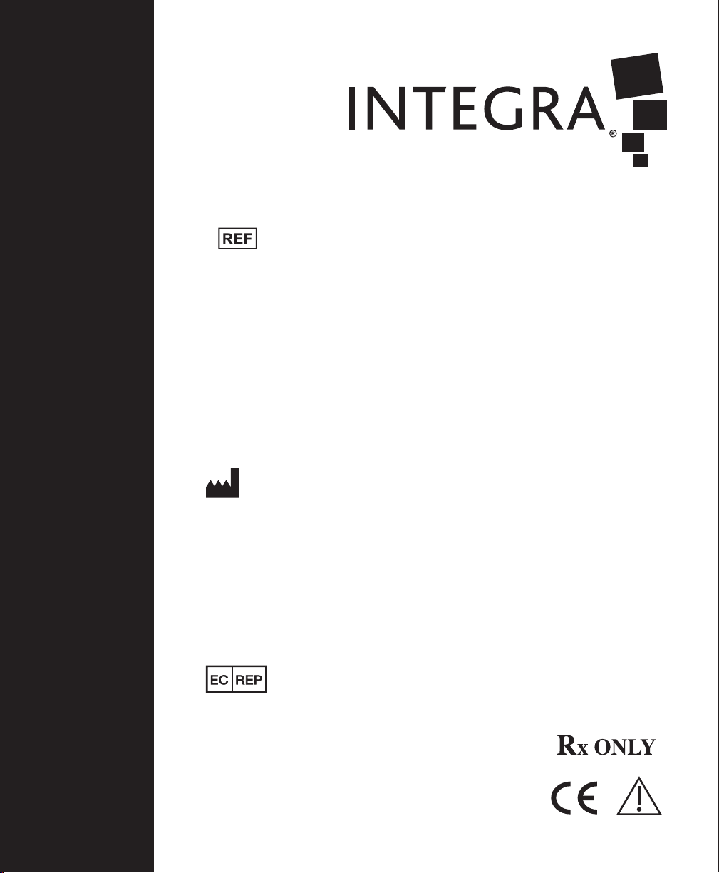
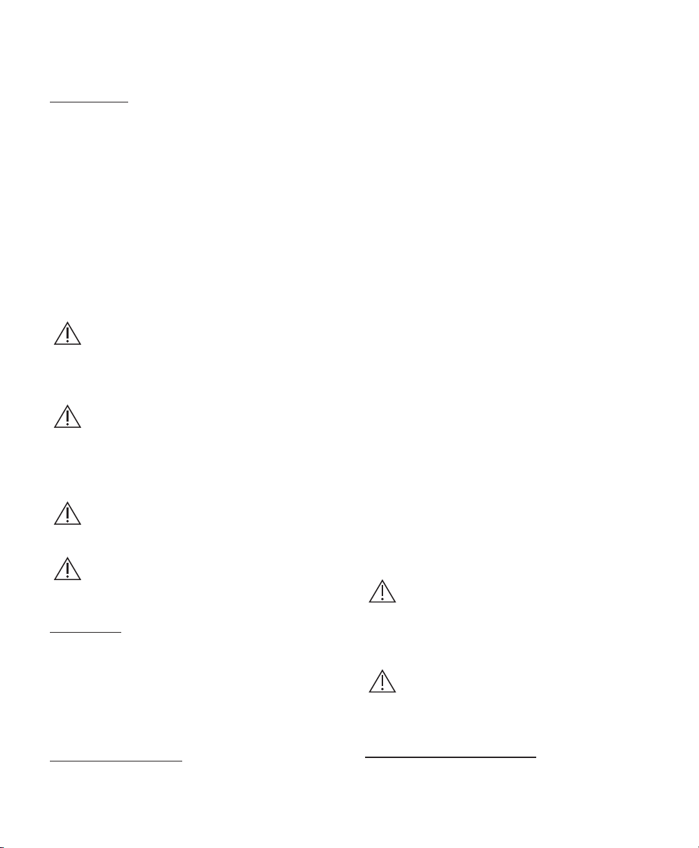
Figure 1
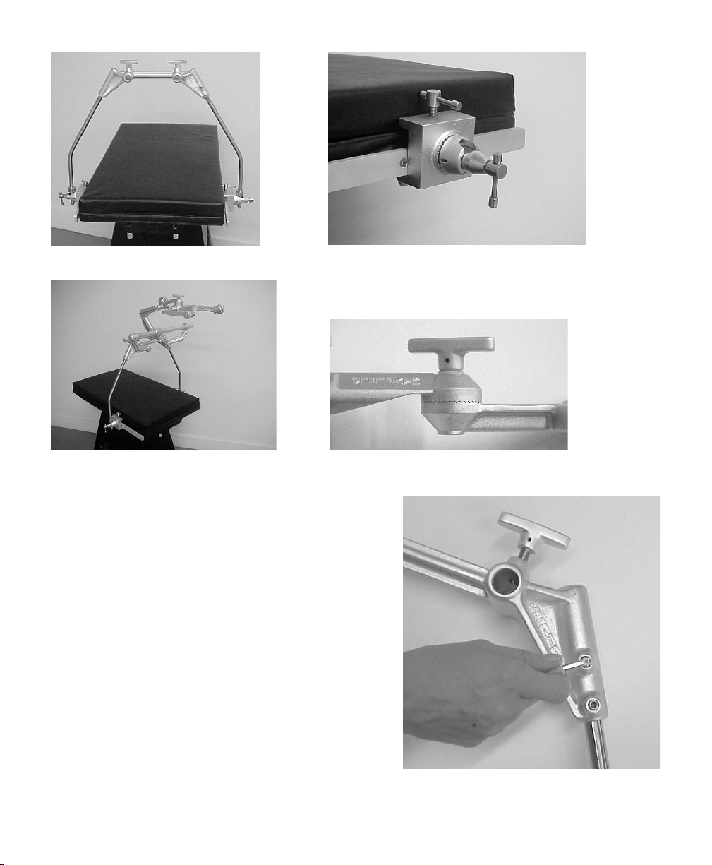
Figure 3
English - Figure 3
Crossbar Adaptor with MAYFIELD Base Unit, Swivel Adaptor,
and Skull Clamp
Deutsch - Abbildung 3
Stangen-Adapter mit MAYFIELD Basiseinheit, Schwenkbare
Adapter und Schädelklemme
Français - Figure 3
Barre de Croisement avec l’Unité de Base MAYFIELD,
l’Adaptateur Pivotant et la Pince du Crâne
Español - Figura 3
Adaptador de barra cruzada con unidad base MAYFIELD,
adaptador giratorio y clamp craneal
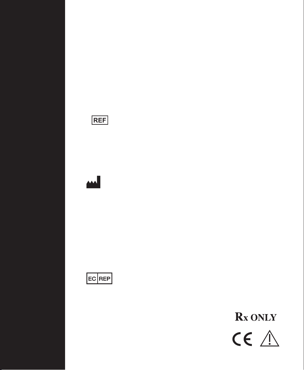
Figure 2
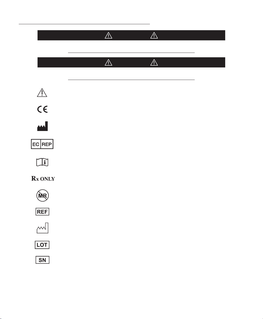
Figure 4
Italiano - Figura 3
Adaatore a barra trasversale con Unità base MAYFIELD,
Adaatore girevole e Testiera
Nederlands - Figuur 3
Dwarsstangadapter met MAYFIELD basisunit, zwenkadapter
en schedelklem
Figure 5
4
Page 5
Meaning Of Symbols Used In This Manual - ENGLISH
CAUTION!
Hazards which could result in equipment or property damage
WARNING!
Hazards which could result in severe personal injury or death
Caution
Product complies with the requirements of directive 93/42/EEC
Manufacturer
Authorized Representative in the European Community
EN – ENGLISH
Consult Instructions for Use
Caution: Federal (USA) law restricts this device to sale by or on the order of a licensed
healthcare practitioner.
This device is not indicated for use in the MR environment
Catalog number
Date of manufacture (YYYY-DD-MM)
Lot number
Serial number
5
Page 6
EN – ENGLISH
ENGLISH
Description
The MAYFIELD® Crossbar Adaptor (REF A-1015 &
A-1016) is designed for procedures requiring siing
positions, primarily the posterior fossa craniotomy and
the posterior cervical laminectomy when performed in
the siing position.
The MAYFIELD Ultra Base Unit (REF A-2101), and the
MAYFIELD Ball Socket Swivel Adaptor (REF A-1064), the
MAYFIELD Swivel Adaptor (REF A-1018), or the MAYFIELD
Tri-Star Adapter (REF A-2008) are required when using the
MAYFIELD Crossbar Adaptor.
If the Operating Table is not equipped with its own side
rail fiings, then the MAYFIELD Universal Side Rail Fiing
(REF A-1060) will be required.
WARNING:
Failure to read and follow instructions furnished
in this product insert may result in skull pin slippage and
serious patient injury, such as scalp lacerations, skull
fracture, or even death.
WARNING:
Failure to properly position patient and to fully
tighten and secure all adjustable portions of this or any
similar device may result in skull pin slippage and serious
patient injury, such as scalp laceration, skull fracture, or
even death.
WARNING:
Do not alter the design of the device in part or
whole as serious patient injury could result.
WARNING:
This device is not intended for use in or near the
vicinity of a strong magnetic field. (MRI)
Inspection
Always inspect instruments before and aer use. If a
component appears damaged and/or does not seem to
function properly, do not use the device and immediately
send the instrument to an authorized Integra repair center
for evaluation, repair or replacement. Allow your Integra
Representative to inspect this device a minimum of two
times per year to assist you in its proper function.
a. Loosen the T-Handle by turning counter-clockwise
and slide onto the side rail making sure the
T-Handle is above the side rail (Figure 2).
b. Lock the T-Handle by turning clockwise.
c. Loosen the Locking Handle by turning counter-
clockwise, in order that the side rail receptacles are
completely open.
2. Mount Crossbar Adaptor to Side Rail Fiings
a. Loosen set screws on Crossbar by turning counter-
clockwise in order to adjust leg widths to that of
the Side Rail Fiings (Figure 5).
b. Holding the Crossbar’s Legs in each hand, insert
each one into the receptacles of the Side Rail
Fiings, adjusting the legs as necessary (Figure 1).
c. Tighten the Locking Handles of the Side Rail
Fiings locking the Crossbar in place.
d. Tighten the set screws on the Crossbar Adaptor by
turning clockwise.
3. Mount MAYFIELD Base Unit to the Crossbar Adaptor
a. Loosen the Crossbar’s Torque Screw Assembly
by turning counter-clockwise. The Crossbar
Receptacles should now be completely open.
b. Insert the Base Unit’s Mounting Bars into the
Crossbar Receptacles.
NOTE:
The Mounting Bars should point away from the patient
(Figure 3).
c. Tighten the Crossbar’s Torque Screws to secure the
Base Unit in place.
4. Aach Swivel Adaptor to Transitional Member of
Base Unit
a. Insert the small ratchet torque screw on Adaptor
into threaded hole on Transitional Member.
b. Turn the Adaptor torque knob clockwise to fully
tighten.
CAUTION:
Always be sure the two sets of sunburst teeth
mesh properly, (Figure 4) when knob is tightened.
Failure to do so may result in damage to the device.
This caution applies to any such fiing in the MAYFIELD
System.
WARNING:
When the patient is finally positioned, make sure
that all aachments are checked and properly
locked into position.
Instructions for Use
1. Mount MAYFIELD Universal Side Rail Fiings to
Operating Room Table
Cleaning and Sterilization
Aer each use, thoroughly clean and wipe the unit with
an antiseptic solution.
6
Page 7
EN – ENGLISH
DO NOT STEAM STERILIZE !
Plastic components may be damaged by heat.
Manual Wash
CAUTIONS
• Alkaline and highly acidic detergents and solutions
cause damage to the devices.
• Channels and crevices found on this device require
particular aention during cleaning.
• Pay special aention to the water quality used
throughout reprocessing. Hard water can damage
the surface of the equipment. Avoid using hard water.
Instead use purified water unless otherwise specified.
Limitations on reprocessing
• Repeated processing has minimal effects on these
devices. Product life is normally determined by wear
and damage due to use.
• It is important to have Integra NeuroSpecialists
perform routine inspections (twice yearly is
recommended). See contact information below.
INSTRUCTIONS
Containment/Transportation
• Follow health care facility protocol for safe
containment and transport to the decontamination
environment.
• It is recommended that devices are cleaned
immediately aer use.
Cleaning – Manual Equipment: Water, Neutral pH
Detergent, So Bristle Brush, Towels
Method
1. Prepare neutral pH enzymatic detergent solution (e.g.
Endozime® AW Triple Plus with APA (Ruhof ), 1:128 ratio)
according to detergent manufacturer’s instructions
using lukewarm tap water.
2. Prepare equipment for soaking by disassembling
removable parts and loosening connections.
3. Rinse equipment in warm water before placing into
bath.
4. Completely soak equipment in water/detergent
solution for 30 minutes maximum.
5. Clean thoroughly with a so nylon bristle brush. NOTE
– If possible, use a disposable brush.
6. Rinse in warm purified water until all visible substances
and residual detergent are removed. NOTE – Make sure
to give special aention to hard-to-reach areas.
7. Thoroughly dry equipment with so clean towels
and use medically compressed air if needed, to dry
channels, crevices and lumens.
8. Inspect the equipment to make sure there is no visible
organic debris or residue from cleaning agent.
Repeat process if any soil is detected.
Drying
• Products should be dry at this point. If wetness or
excess liquid is detected, dry with a so clean towel.
• Medically compressed air can be used if needed.
Optional Automatic Wash / Disinfect
CAUTIONS
• Alkaline and highly acidic detergents and solutions
cause damage to the devices.
• Channels and crevices found on these devices require
particular aention during cleaning.
• Pay special aention to the water quality used
throughout reprocessing. Hard water can damage
the surface of the equipment. Avoid using hard water.
Instead use purified water unless otherwise specified.
Limitations on Reprocessing
• Repeated processing has negative effects on these
devices and is not recommended for routine use.
• It is important to have Integra NeuroSpecialists
perform routine inspections (twice yearly is
recommended).
See contact information.
INSTRUCTIONS
Cleaning - Automated Equipment: Neutral pH Detergent
Method
1. Prepare equipment for cleaning by disassembling
removable parts and loosening connections.
2. Rinse equipment in warm water before placing into
washer.
3. Load device into the washer and place small parts in
container or tray inside the washer unit in order to
avoid loosing small components.
NOTE – Load devices carefully into washer in order
to avoid collision.
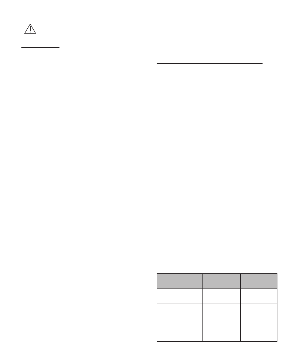
4. Follow the instructions listed below and set washer
machine to these exact parameters:
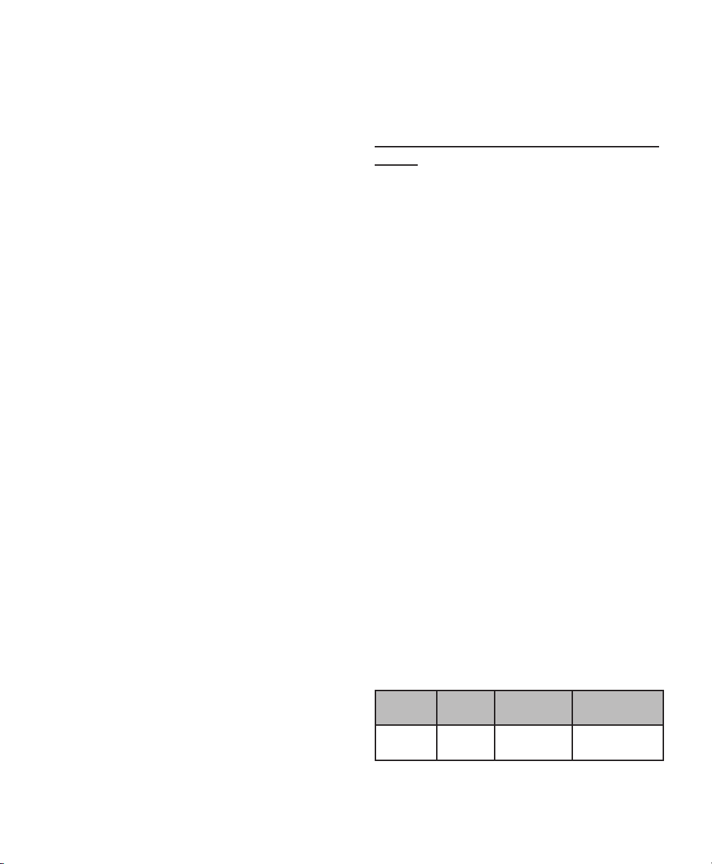
Phase Time
(Min.)
Pre-wash 14:00 Cold water N/A
Enzyme
Wash
4:00 Hot water Neutral pH
Water Temperature
Detergent and
Concentration
enzymatic (e.g.
Endozime® AW
Triple Plus with
APA, Ratio
1:128)
7
Page 8
EN – ENGLISH
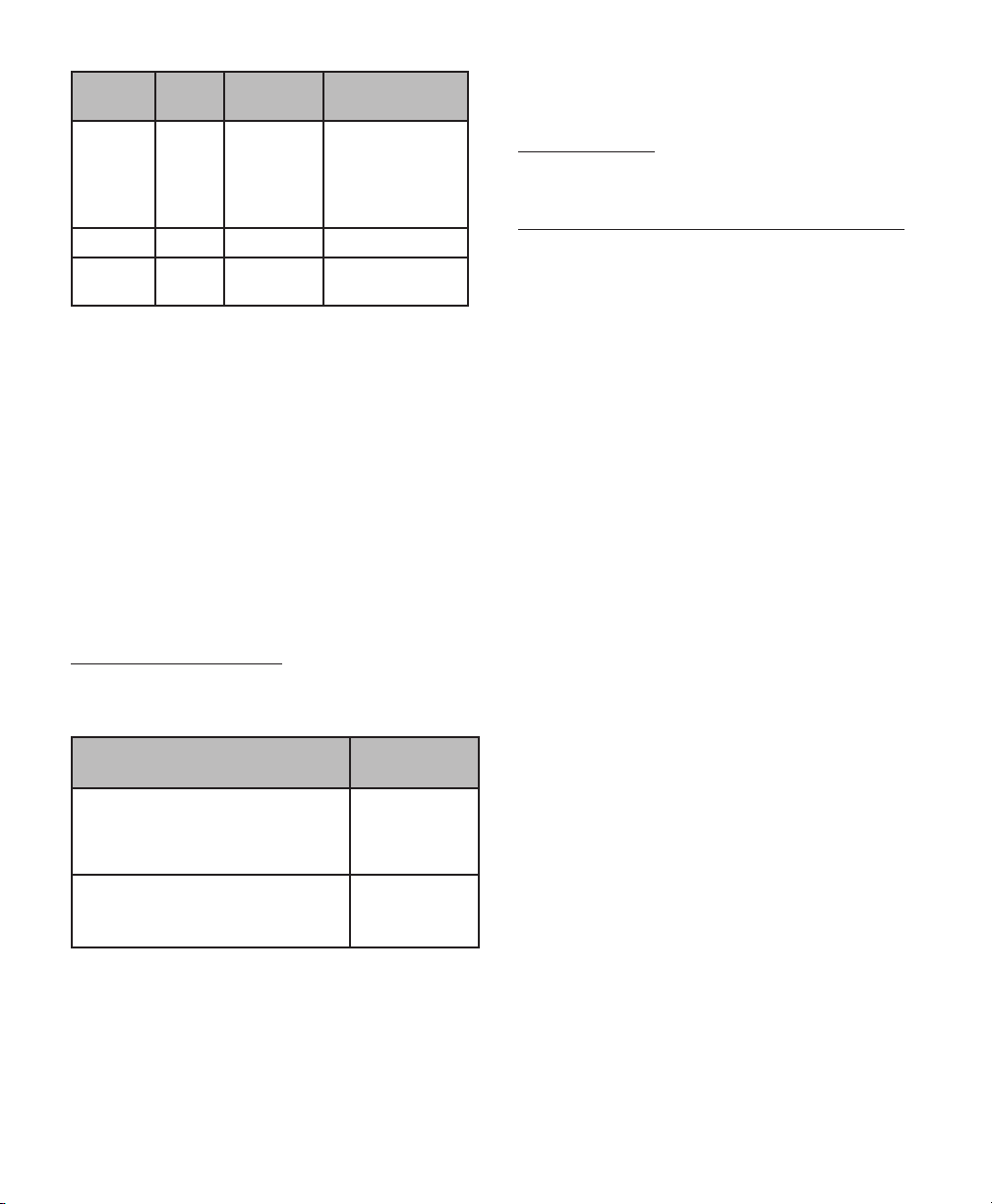
Phase Time
(Min.)
Wash 1 10:00 60.0°C
Rinse 1 0:30 Hot water N/A
Thermal
Rinse**
** Optional phase for disinfection of components –
minimum water temperature as indicated or per worker
manufacturer specifications for the thermal rinse cycle.
NOTE – Any deviation from this guideline could result in
damage to the equipment as well as improper cleaning
results.
Rinse with purified water. Do not perform if parameters
cannot be achieved.
5. Remove from washer and dry completely if needed.
6. Inspect equipment to make sure there is no visible
organic debris or residue from cleaning agent.
Repeat process if any visible soil is detected.
2:00 82.2°C (180° F)N/A
Water Temperature
(140° F)
Detergent and
Concentration
Neutral pH
detergent
(e.g. Renu-Klenz™
, Steris, Ratio
1:256)
Maintenance and Care
To ensure proper function and to extend the life and
performance of the equipment, Integra LifeSciences
recommends the following:
Recommended Action Recommended
Frequency
Return the device to the Integra
LifeSciences Repairs department for
detailed inspection and servicing.
Once / year
See Inspection and/or Service notes section for routine
checks to be performed on the device.
Device Disposal
NOTE: Follow hospital procedures for disposal of this device.
Integra LifeSciences Warranty Statement
INTEGRA LIFESCIENCES CORPORATION (“INTEGRA”)
warrants to the original purchaser only that each new
MAYFIELD product is free from manufacturing defects in
material and workmanship under normal use and service
for a period of one year (except as otherwise expressly
provided as to accessory items) from the date of delivery
by INTEGRA to the first purchaser, but in no event beyond
the expiration date stated on any product labeling.
• Surgical instruments are guaranteed to be free
from defects in material and workmanship when
maintained and cleaned properly and used normally
for their intended purpose.
• Any covered product that is placed by INTEGRA
under a lease, rental or installment purchase
agreement and that requires repair service during
the term of such placement agreement shall be
repaired in accordance with the terms of such
agreement.
If any covered defect occurs during the warranty period
or term of such placement agreement, the purchaser
should communicate directly with INTEGRA’s home
office. If purchaser seeks to invoke the terms of this
warranty, the product must be returned to INTEGRA at its
home office. The defective product should be returned
promptly, properly packaged and postage prepaid. Loss
or damage in return shipment to INTEGRA shall be at
CUSTOMER’s risk. INTEGRA’s sole responsibility under
this warranty shall be repair or replacement, at INTEGRA’s
sole discretion at INTEGRA’s expense, subject to the terms
of this warranty and applicable agreements.
Request that Integra NeuroSpecialists
perform routine inspections of the
device
In the absence of proper care and servicing of the device,
negative effects may be seen aer repeated processing
over time which may lead to reduced performance.
Contact information: See the Service and Repair section
for contact information on how to return your device for
periodic servicing and to request periodic inspections.
Twice / year
IN NO EVENT SHALL INTEGRA BE LIABLE FOR ANY
INCIDENTAL, INDIRECT, CONSEQUENTIAL OR PUNITIVE
DAMAGES IN CONNECTION WITH THE ACQUISITION
OR USE OF ANY INTEGRA PRODUCT. Further, this
warranty shall not apply to, and INTEGRA shall not be
responsible for, any loss arising in connection with the
purchase or use of any INTEGRA product that has been
repaired by anyone other than an authorized INTEGRA
service representative or altered in any way so as, in
INTEGRA’s judgment, to affect its stability or reliability,
or which has been subject to misuse, negligence or
accident, or which has been used otherwise than in
8
Page 9

accordance with the instructions furnished by INTEGRA.
THIS LIMITED WARRANTY IS EXCLUSIVE AND IN LIEU
OF ALL OTHER WARRANTIES, EXPRESSED OR IMPLIED,
AND OF ALL OTHER OBLIGATIONS OR LIABILITIES ON
INTEGRA’S PART, AND INTEGRA NEITHER ASSUMES
NOR AUTHORIZES ANY REPRESENTATIVE OR OTHER
PERSON TO ASSUME FOR IT ANY OTHER LIABILITY IN
CONNECTION WITH INTEGRA’S PRODUCTS. INTEGRA
DISCLAIMS ALL OTHER WARRANTIES, EXPRESSED OR
IMPLIED INCLUDING ANY IMPLIED WARRANTY OF
MERCHANTABILITY OR OF FITNESS FOR A PARTICULAR
PURPOSE OR APPLICATION OR WARRANTY OF QUALITY
AS WELL AS ANY EXPRESSED OR IMPLIED WARRANTY
TO PATIENTS. No warranty or guarantee may be created
by any act or statement nor may this Standard Warranty
be modified in any way, except as a result of a writing
signed by an officer of INTEGRA. These limitations on
the creation or modification of this warranty may not be
waived or modified orally or by any conduct.
Service and Repair
For service and repairs outside the United States, contact
your local authorized Integra representative.
Inside the United States, send all instruments for service
or repair to:
EN – ENGLISH
Integra LifeSciences Corporation
4900 Charlemar Drive, Building A
Cincinnati, Ohio 45227
(Always include the purchase order number and a wrien
description of the problem).
Or phone: 877-444-1114(USA only)
513-533-7979
9
Page 10

EN – ENGLISH
Manufacturer:
Integra LifeSciences Corporation
4900 Charlemar Drive, Building A
Cincinnati, OH 45227, USA
Tel: 513-533-7979
Fax: 513-271-1915
integralife.com
Integra LifeSciences Services (France) SAS
Immeuble Séquoia 2
97 allée Alexandre Borodine
Parc Technologique de la Porte des Alpes
69800 Saint Priest, FRANCE
Phone: +33 (0) 4 37 47 59 00
Fax: +33 (0) 4 37 47 59 99
Integra and the Integra logo are registered trademarks of Integra LifeSciences Corporation in the United States and/or
other countries. MAYFIELD is a registered trademark of SM USA, Inc. and is used by Integra under license. Endozime is a
trademark of Ruhof Corporation. Renu-Klenz is a trademark of Steris Corporation.
2017 Integra LifeSciences Corporation. All Rights Reserved. 451A1015 Rev. C 11/17 0845548-1
10
Page 11
Barre de Croisement
MAYFIELD®
( - A1015 & A1016)
Mode d’emploi
Fabricant:
Integra LifeSciences Corporation
4900 Charlemar Drive, Building A
Cincinnati, OH 45227, États-Unis
Tél: 513-533-7979
Télécopie: 513-271-1915
integralife.com
FR – Français
Integra LifeSciences Services (France) SAS
Immeuble Séquoia 2
97 allée Alexandre Borodine
Parc Technologique de la Porte des Alpes
69800 Saint Priest, FRANCE
Phone: +33 (0) 4 37 47 59 00
Fax: +33 (0) 4 37 47 59 99
11
Page 12

FR – FRANÇAIS
Figure 1
Figure 3
English - Figure 3
Crossbar Adaptor with MAYFIELD Base Unit, Swivel Adaptor,
and Skull Clamp
Deutsch - Abbildung 3
Stangen-Adapter mit MAYFIELD Basiseinheit, Schwenkbare
Adapter und Schädelklemme
Français - Figure 3
Barre de Croisement avec l’Unité de Base MAYFIELD,
l’Adaptateur Pivotant et la Pince du Crâne
Español - Figura 3
Adaptador de barra cruzada con unidad base MAYFIELD,
adaptador giratorio y clamp craneal
Figure 2
Figure 4
Italiano - Figura 3
Adaatore a barra trasversale con Unità base MAYFIELD,
Adaatore girevole e Testiera
Nederlands - Figuur 3
Dwarsstangadapter met MAYFIELD basisunit, zwenkadapter
en schedelklem
Figure 5
12
Page 13
Signification des symboles utilisés dans ce manuel - FRANÇAIS
ATTENTION!
Dangers pouvant causer des dommages au matériel ou à aux biens
AVERTISSEMENT!
Dangers pouvant causer des blessures personnelles graves, voire fatales
Aention, consulter la documentation jointe
Ce produit est conforme aux exigences de la directive 93/42/CEE
Fabricant
Représentant autorisé dans la Communauté européenne
FR – FRANÇAIS
Consulter le mode d’emploi
Aention : la loi fédérale américaine réserve la vente de ce dispositif par ou sur
prescription d’un médecin ou d’un praticien.
Il est déconseillé d’utiliser cet appareil pour la résonance magnétique
Référence catalogue
Date de fabrication
Numéro de lot
N° de série
13
Page 14
FR – FRANÇAIS
FRANÇAIS
Description
La Barre de Croisement MAYFIELD® (REF A-1015 & A-1016)
est spécialement cooncue pour les interventions nécessitant
les positions assises, notamment en craniotomie de la fosse
postérieure ou laminectome cervicale postérieure.
La Barre de Croisement est utilisée avec l’Unité de Base Ultra
(REF A-2101), l’Adaptateur sur Socle à Boule (REF A-1064), ou
l’Adaptateur (REF A-1018) ou l’Adaptateur MAYFIELD Tri-Star
(REF A-2008).
Si la table d’opération n’est pas équipée des fixations
latérales, les fixations latérales universelles MAYFIELD
(REF A-1060) doivent être utilisées.
AVERTISSEMENT:
Le fait de ne pas lire et de ne pas respecter les
instructions fournies dans la notice de ce produit peut
exposer le patient à des blessures graves.
AVERTISSEMENT:
Le fait de ne pas positionner correctement le patient
et de ne pas complètement fixer toutes les portions de
réglage de ce dispositif ou de tout dispositif de soutien
pourrait exposer le patient à des risques de blessures.
AVERTISSEMENT:
Ne pas modifier, toute ou une partie de la
conception du dispositif sous peine d’exposer le patient à
des blessures graves.
AVERTISSEMENT:
Ce dispositif n’est pas conçu pour être utlisé à
proximité d’un champ magnétique puissant (IRM)
Inspection
Toujours vérifier les instruments avant et après leur
utilisation. Si un élément semble endommagé et/ou ne pas
fonctionner correctement, ne pas utiliser le dispositif et
l’envoyer immédiatement à un centre de réparation Integra
agréé où il sera évalué, réparé ou remplacé. Faire vérifier ce
dispositif par votre représentant Integra au moins deux fois
par an pour veiller à son fonctionnement correct.
Mode d’Emploi
1. Monter les fixations latérales universelles sur la table
d’opération
a. Desserrer la manee en T en tournant dans les sens
contraire des aiguilles d’une montre et glisser sur le
rail latéral en s’assurant que la manee en T est au
dessus du rail (Figure 2).
b. Serrer la manee en T en tournant dans le sens des
aiguilles d’une montre.
c. Desserrer la manee de verrouillage en tournant
dans le sens contraire des aiguilles d’une
montre pour que les réceptacles des rail soient
complètement ouverts.
2. Monter la Barre de Croisement sur les fixations latérales
a. Desserrer les vis sur la Barre de Croisement en
tournant dans le sens contraire des aiguilles d’une
montre afin d’ajuster l’écartement des tiges en
fonction des fixations latérales (Figure 5).
b. En maintenant chaque tige dans une main, les insérer
dans leurs réceptacles (Figure 1).
c. Serrer les manees des fixations latérales pour fixer
la Barre de Croisement.
d. Serrer les vis de la Barre de Croisement en tournant
dans le sens des aiguilles d’une montre.
3. Monter l’Unité de Base sur la Barre de Croisement
a. Desserrer les vis de torsion en tournant dans le sens
contraire des aiguilles d’une montre. Les réceptacles
de la Barre de Croisement seront complètement
ouverts maintenant.
b. Insérer les tiges de l’Unité de Base dans les
réceptacles de la Barre de Croisement.
IMPORTANT:
Les tiges de l’Unité de Base sont fixées
horizontalement à la table d’opération en partant de la
tête de patient vers les pieds (Fig. 3).
c. Serrer les vis de torsion de la Barre de Croisement
pour fixer l’Unité de Base.
4. Monter l’Adaptateur MAYFIELD sur le Dispositif de
Transition de l’Unité de Base
a. Insérer la vis de torsion de la petite piece crantée
dans le réceptacle du Dispositif de Transition.
b. Tourner dans le sens des aiguilles d’une montre et
serrer à fond.
ATTENTION:
Il faut toujours ‘assurer que les deux parties crantées sont
bien engrenées (Figure 4) avant de serrer la vis. Le non-respect de
cee mesure entraînera l’endommagement du matériel.
AVERTISSEMENT:
Lorsque le patient est finalement positionné, vérifier
que le système et ses accessoires sont bien fixés.
Neoyage et Sterilisation
Neoyer soigneusement après chaque utilisation avec une
solution antiseptique.
NE PAS PASSER A L’ AUTOCLAVE!
Les composants en plastique seront endommagés.
Lavagemanuel
MISES EN GARDE
• Des solutions et des détergents alcalins et fortement
acides peuvent endommager les dispositifs.
14
Page 15
FR – FRANÇAIS
• Les canaux et fentes présentes sur ce dispositif
nécessitent une aention particulière au cours du
neoyage.
• Faire particulièrement aention à la qualité de l’eau
utilisée pendant tout le reconditionnement. De l’eau dure
peut endommager la surface du matériel. Éviter d’utiliser
une eau dure. Utiliser à la place une eau purifiée, sauf
mention contraire.
Limites du reconditionnement
• Un reconditionnement répété a peu d’effets sur ces
dispositifs. La durée de vie des produits est normalement
déterminée par l’usure et par les dommages liés à l’usure.
• Il est important que les neuro-spécialistes d’Integra
effectuent des inspections régulières (une fréquence de
deux fois par an est recommandée). Voir les coordonnées
ci-dessous.
INSTRUCTIONS
Confinement/Transport
• Respecter le protocole de l’établissement hospitalier
concernant le confinement et le transport en toute
sécurité du matériel jusqu’à la zone de décontamination.
• Il est recommandé de neoyer les dispositifs
immédiatement après usage.
Neoyage – Équipement pour le neoyage manuel :
Eau, détergent à pH neutre, brosse à poils doux, linges
Méthode
1. Préparer une solution de détergent enzymatique de
pH neutre (par exemple Endozime® AW Triple Plus avec
APA (Ruhof), dans un rapport 1/128) conformément aux
instructions du fabricant du détergent en utilisant une
eau du robinet tiède.
2. Préparer le matériel au trempage en démontant les parties
amovibles et en desserrant les joints.
3. Rincer le matériel à l’eau chaude avant de le mere dans
le bain.
4. Tremper complètement le matériel dans la solution d’eau/
détergent pendant un maximum de 30 minutes.
5. Neoyer soigneusement et complètement avec une
brosse à poils doux en nylon. REMARQUE – Si possible,
utiliser une brosse jetable.
6. Rincer dans de l’eau purifiée chaude jusqu’à ce que
toutes les substances visibles et les traces résiduelles
de détergent aient été éliminées. REMARQUE– Veiller à
porter une aention particulière aux endroits difficiles
d’accès.
7. Sécher complètement le matériel avec des linges propres
et doux et utiliser si besoin de l’air comprimé médical
pour sécher les canaux, fentes et lumières.
8. Examiner le matériel pour s’assurer qu’il ne présente pas
de débris organiques visibles ou de résidus de l’agent de
neoyage.
Séchage
• À ce stade, les produits doivent être secs. Si de l’humidité
ou un excès de liquide est détecté, sécher en utilisant un
linge propre et doux.
• De l’air comprimé médical peut être utilisé si besoin.
Lavage/désinfection automatique optionnel(le)
MISES EN GARDE
• Des solutions et des détergents alcalins et fortement
acides peuvent endommager les dispositifs.
• Les canaux et fentes présentes sur ces dispositifs
nécessitent une aention particulière pendant le
neoyage.
• Faire particulièrement aention à la qualité de l’eau
utilisée pendant tout le reconditionnement. De l’eau dure
peut endommager la surface du matériel. Éviter d’utiliser
une eau dure. Utiliser à la place une eau purifiée, sauf
mention contraire.
Limites du reconditionnement
• Un reconditionnement répété a des effets négatifs
sur ces dispositifs et n’est pas recommandé pour une
utilisation régulière.
• Il est important que les neuro-spécialistes d’Integra
effectuent des inspections régulières (une fréquence de
deux fois par an est recommandée).
Voir les coordonnées.
INSTRUCTIONS
Neoyage - Équipement automatisé : Détergent à pH
neutre
Méthode
1. Préparer le matériel au neoyage en démontant les
parties amovibles et en desserrant les joints.
2. Rincer le matériel à l’eau chaude avant de le mere dans la
laveuse.
3. Charger le dispositif dans la laveuse et placer les petites
pièces dans un contenant ou dans un plateau à l’intérieur
de la laveuse de façon à éviter de perdre ces petits
éléments.
REMARQUE – Charger les dispositifs avec soin dans la
laveuse de façon à éviter des collisions.
4. Suivre les instructions énumérées ci-dessous et régler la
laveuse selon ces paramètres exacts :
Phase Temps
(Min.)
Prélavage
4 min 00 Eau froide S/O
: 1
Température
de l’eau
Détergent et
concentration
Répéter le processus en cas de souillure visible.
15
Page 16

FR – FRANÇAIS
Phase Temps
(Min.)
Lavage
4 min 00 Eau chaude pH
aux
enzymes
Température
de l’eau
Détergent et
concentration
enzymatique
neutre (par
exemple,
Endozime® AW
Triple Plus avec
APA, Rapport
1/128)
Lavage 1 10 min 0060,0 °C (140
°F)
Détergent à
pH neutre (par
exemple, RenuKlenz™, Steris,
Ratio 1/256)
Rinçage 1 0 min 30 Eau chaude S/O
Rinçage à
chaud**
** Phase facultative de désinfection des composants :
température minimum de l’eau telle qu’indiquée ou selon
les spécifications du fabricant par utilisateur pour le cycle
de rinçage à chaud.
REMARQUE : Tout écart par rapport à ces instructions
risquerait d’endommager le matériel et de réduire
l’efficacité du neoyage.
Rincer avec de l’eau purifiée. Ne pas le faire si les
paramètres ne peuvent pas être obtenus.
5. Retirer de la laveuse et sécher complètement si nécessaire.
6. Examiner tous les éléments pour vérifier qu’ils ne
comportent pas de débris organiques visibles ni de résidus
de l’agent de neoyage.
2 min 00 82,2 °C (180
°F)
S/O
encourus lors de l’expédition à INTEGRA LIFESCIENCES.
en aucun cas integra lifesciences ne se porte responsable de
dommages secondaires, indirects, consécutifs ou punitifs
en rapport avec l’acquisition ou l’utilisation d’un produit
INTEGRA lifesciences. En outre, cee garantie ne s’applique
pas et INTEGRA LIFESCIENCES n’est pas responsable en
cas de dommages survenant par suite de l’achat ou de
l’utilisation d’un produit INTEGRA LIFESCIENCES qui a été
réparé par quelqu’un d’autre qu’un technicien agréé par
INTEGRA LIFESCIENCES ou a été modifié de telle façon que,
à l’avis d’INTEGRA LIFESCIENCES, sa stabilité ou sa fiabilité
en est affectée ou a souffert d’un usage abusif, de négligence
ou d’un accident ou a été utilisé de manière non conforme
aux directives fournies par INTEGRA LIFESCIENCES. CETTE
GARANTIE LIMITÉE EST EXCLUSIVE ET REMPLACE TOUTES
LES AUTRES GARANTIES, TANT EXPRESSES QUE TACITES, ET
TOUTES LES AUTRES OBLIGATIONS OU RESPONSABILITÉS
D’INTEGRA LIFESCIENCES, ET INTEGRA LIFESCIENCES
N’ACCEPTE NI AUTORISE UN REPRÉSENTANT OU UNE
AUTRE PERSONNE À ACCEPTER EN SON NOM TOUTE
AUTRE RESPONSABILITÉ EN RAPPORT AVEC LES PRODUITS
INTEGRA LIFESCIENCES.
INTEGRA LIFESCIENCES REJETTE TOUTES LES AUTRES
GARANTIES EXPRESSES OU TACITES, Y COMPRIS TOUTE
GARANTIE TACITE DE COMMERCIALITÉ OU D’APTITUDE
À UN USAGE, UNE APPLICATION OU UNE GARANTIE DE
QUALITÉ SPÉCIFIQUE, AUTRES QUE CELLES EXPRESSÉMENT
INDIQUÉES DANS LA DOCUMENTATION DU PRODUIT,
Y COMPRIS L’INFORMATION D’USAGER APPLICABLE. Ce
qui précède ne libère pas INTEGRA LIFESCIENCES de sa
responsabilité délictuelle, si autrement applicable sous la
loi en vigueur, de dommages dus à un préjudice corporel
causé par un vice de produit rendant le produit indûment
dangereux au moment de la vente ou de l’installation.
Répéter le processus en cas de souillure visible.
Garantie
INTEGRA LIFESCIENCES garantit que chaque nouveau
produit INTEGRA LIFESCIENCES est libre de vices de
matériaux et de fabrication sous réserve d’un usage et d’un
service normal pendant une période d’un an (sauf lorsque
expressément stipulé différemment en ce qui concerne les
accessoires), à partir de la date de livraison par INTEGRA
LIFESCIENCES à l’acheteur initial jusqu’à la date d’expiration
indiquée sur l’étiquee de chaque produit. Les instruments
chirurgicaux MAYFIELD sont garantis libres de vices de
matériaux et de fabrication lorsqu’ils sont utilisés de manière
normale pour les fonctions prévues. INTEGRA LIFESCIENCES,
à sa discrétion, réparera ou remplacera à ses frais tout
produit couvert sous la garantie qui lui a été renvoyé,
sous réserve des conditions de la présente garantie et des
accords applicables. Un produit défectueux doit être renvoyé
promptement, port payé et emballé de manière appropriée.
Le CLIENT est responsable des pertes ou des dommages
Maintenance et réparation
Pour la maintenance et les réparations à l’extérieur des EtatsUnis, prendre directement contact avec le représentant agréé
Integra de votre région.
Aux Etats-Unis, envoyer tous les instruments pour la
maintenance ou les réparations à:
Integra LifeSciences Corporation
4900 Charlemar Drive, Building A
Cincinnati, Ohio 45227
(Toujours joindre le numéro du bon d’achat et une
description écrite du problème).
Ou téléphoner au:
877-444-1114 (Etats-Unis seulement)
513-533-7979
16
Page 17

Fabricant:
FR – FRANÇAIS
Integra LifeSciences Corporation
4900 Charlemar Drive, Building A
Cincinnati, OH 45227, États-Unis
Tél: 513-533-7979
Télécopie: 513-271-1915
integralife.com
Integra LifeSciences Services (France) SAS
Immeuble Séquoia 2
97 allée Alexandre Borodine
Parc Technologique de la Porte des Alpes
69800 Saint Priest, FRANCE
Phone: +33 (0) 4 37 47 59 00
Fax: +33 (0) 4 37 47 59 99
Integra et le logo Integra sont des marques déposées d’Integra LifeSciences Corporation aux États-Unis et/ou dans
d’autres pays. MAYFIELD est une marque déposée de SM USA, Inc. et est utilisée par Integra sous licence. Endozime est
une marque commerciale de Ruhof Corporation. Renu-Klenz est une marque commerciale de Steris Corporation.
©2014 Integra LifeSciences Corporation. Tous droits réservés.
451A1015 Rev. B
17
Page 18

This page is intentionally le blank
18 19
Page 19

IT – Italiano
Barra trasversale per unità di base
MAYFIELD®
( - A1015 & A1016)
Manuale di istruzioni
Produore:
Integra LifeSciences Corporation
4900 Charlemar Drive, Building A
Cincinnati, OH 45227, USA
Tel: 513-533-7979
Fax: 513-271-1915
integralife.com
Integra LifeSciences Services (France) SAS
Immeuble Séquoia 2
97 allée Alexandre Borodine
Parc Technologique de la Porte des Alpes
69800 Saint Priest, FRANCE
Phone: +33 (0) 4 37 47 59 00
Fax: +33 (0) 4 37 47 59 99
Page 20

IT – ITALIANO
Figura 1
Figura 3
English - Figure 3
Crossbar Adaptor with MAYFIELD Base Unit, Swivel Adaptor,
and Skull Clamp
Deutsch - Abbildung 3
Stangen-Adapter mit MAYFIELD Basiseinheit, Schwenkbare
Adapter und Schädelklemme
Français - Figure 3
Barre de Croisement avec l’Unité de Base MAYFIELD,
l’Adaptateur Pivotant et la Pince du Crâne
Español - Figura 3
Adaptador de barra cruzada con unidad base MAYFIELD,
adaptador giratorio y clamp craneal
Figura 2
Figura 4
Italiano - Figura 3
Adaatore a barra trasversale con Unità base MAYFIELD,
Adaatore girevole e Testiera
Nederlands - Figuur 3
Dwarsstangadapter met MAYFIELD basisunit, zwenkadapter
en schedelklem
Figura 5
20 21
Page 21

Significato dei simboli usati in questo Manuale - ITALIANO
ATTENZIONE!
Pericoli che potrebbero risultare in danni ad apparecchiature o proprietà
AVVERTENZA!
Pericoli che potrebbero risultare in gravi lesioni personali o morte
Aenzione, consultare la documentazione allegata
Il prodoo è conforme ai requisiti della Direiva 93/42/CEE
Società produrice
Rappresentante autorizzato nella Comunità Europea
IT – ITALIANO
Consultare le istruzioni per l’uso
Aenzione: la Legge Federale degli Stati Uniti limita la vendita di questo
dispositivo tramite o su ordine di un medico.
Questo dispositivo non è indicato per l’uso in ambiente RM
Numero di catalogo
Data di fabbicazione
Numero di loo
Numero di serie
Page 22

IT – ITALIANO
ITALIANO
Descrizione
La barra trasversale per unità di base MAYFIELD® (REF
A-1015) è progeata per procedure che richiedono una
posizione seduta, principalmente craniotomia della fossa
posteriore e laminectomia cervicale posteriore eseguite
in posizione seduta.
Per l’uso della barra trasversale MAYFIELD sono necessari
l’unità di base Ultra MAYFIELD (REF A-2101) e l’adaatore
snodo a giunto sferico MAYFIELD (REF A-1064) con
l’adaatore snodo standard MAYFIELD (REF A-1018) o
l’adaatore Tri-Star MAYFIELD (REF A-2008).
Se il tavolo operatorio non è provvisto di un suo supporto
laterale scorrevole, sarà necessario il supporto laterale
scorrevole MAYFIELD (REF A-1060).
AVVERTENZA:
La mancata leura e il mancato rispeo delle
istruzioni fornite nel presente inserto del prodoo
possono causare gravi lesioni al paziente.
AVVERTENZA:
Il posizionamento scorreo del paziente e il
mancato fissaggio di tue le posizioni di regolazione di
questo dispositivo o di qualsiasi dispositivo di supporto
possono causare gravi lesioni al paziente.
AVVERTENZA:
Non alterare il design del dispositivo in parte o
integralmente in quanto questo potrebbe causare gravi
lesioni al paziente.
AVVERTENZA:
Questo dispositivo non è indicato per l’uso in
prossimità di o in un forte campo magnetico (RM).
Controlli
Ispezionare sempre gli strumenti prima e dopo l’uso. Se
un componente appare danneggiato e/o non sembra
funzionare correamente, non usare il dispositivo e
inviare immediatamente lo strumento a un centro di
riparazione Integra autorizzato per essere valutato,
riparato o sostituito. Richiedere al rappresentante Integra
di ispezionare il dispositivo almeno due volte all’anno per
assistervi affinché funzioni correamente.
Istruzioni Per L’uso
1. Montare il supporto laterale scorrevole al tavolo
della sala operatoria
a. Allentare l’impugnatura a T girando in senso
antiorario e far scorrere sulle rotaie laterali
assicurandosi che l’impugnatura a T sia rivolta
verso l’alto (Figura 2).
b. Bloccare l’impugnatura a T girando in senso orario
c. Allentare l’impugnatura di serraggio girando in
senso antiorario in modo che i riceacoli del
supporto laterale siano completamente aperti.
2. Montare la Barra trasversale sul supporto laterale
scorrevole
a. Allentare le viti sulla barra girando in senso
antiorario in modo da regolare l’ampiezza delle
staffe laterali della barra trasversale a quelle del
supporto laterale scorrevole (Figura 5).
b. Tenendo in mano entrambe le staffe laterali
della barra trasversale, inserirle nei riceacoli
del supporto laterale regolandole se necessario
(Figura 1).
c. Avvitare l’impugnatura di serraggio del supporto
laterale bloccando la barra trasversale.
d. Avvitare le viti sulla barra trasversale girando in
senso orario
3. Montare l’Unità di base MAYFIELD alla Barra
trasversale
a. Allentare le viti di collegamento poste sul
riceacolo per l’unità base posto sulla barra
trasversale girando in senso antiorario sino alla
completa apertura.
b. Inserire le barre dell’unità di base nei rispeivi
riceacoli della barra trasversale.
NOTA:
Le barre devono puntare lontano dal paziente
(Figura 3).
c. Avvitare la vite di collegamento della barra
trasversale per fissare l’unità di base nella sua
posizione.
4. Aaccare l’adaatore snodo alla staffa transizionale
dell’unità di base
a. Inserire la vite di collegamento all’interno della
corona dentata piccola sull’adaatore nel foro
fileato sulla staffa transizionale
b. Girare l’impugnatura a T dell’adaatore in senso
orario fino ad avvitarlo completamente.
ATTENZIONE:
Assicurarsi sempre che le due metà della corona
dentata ingranino correamente (come mostrato in
figura 4) quando l’impugnatura è avvitata. Errori in
questa operazione possono causare danni ai dentini.
Questa precauzione è da applicarsi a tui i componenti
del sistema MAYFIELD.
AVVERTENZA:
Quando il paziente è posizionato, assicurarsi che
tui gli accessori siano controllati e bloccati in modo
appropriato in posizione.
22 23
Page 23

IT – ITALIANO
Pulizia e sterilizzazione
Dopo ogni uso pulire a fondo e detergere l’unità con una
soluzione antiseica.
NON STERILIZZARE A VAPORE!
I componenti di plastica possono danneggiarsi
con il calore.
Lavaggio a mano
PRECAUZIONI
• Soluzioni e detergenti alcalini e altamente acidi
causano danni ai dispositivi.
• Le scanalature e le fessure presenti sul dispositivo
richiedono un’aenzione particolare durante la pulizia.
• Prestare particolare aenzione alla qualità dell’acqua
usata durante il ritraamento. L’acqua dura può
danneggiare la superficie dell’apparecchiatura. Evitare
l’uso di acqua dura. Se non altrimenti specificato, fare
uso di acqua depurata.
Limitazioni di ritraamento
• Il traamento ripetuto ha un impao minimo su questi
dispositivi. La durata dei prodoi viene determinata
normalmente dall’usura e dai danni dovuti all’uso.
• È importante che i nuerospecialisti Integra eseguano le
ispezioni di routine (si consiglia due volte all’anno). Fare
riferimento alle informazioni di contao più avanti.
ISTRUZIONI
Contenimento/Trasporto
• Aenersi al protocollo della struura sanitaria relativo
al contenimento e al trasporto sicuri all’ambiente di
decontaminazione.
• Si consiglia di pulire i dispositivi immediatamente
dopo l’uso.
Pulizia - Arezzatura manuale: acqua, detergente a pH
neutro, spazzola con setole morbide, salviee
Metodo
1. Preparare la soluzione detergente enzimatica a pH
neutro [ad es., Endozime® AW Triple Plus con APA
(Ruhof), rapporto 1:128] in conformità alle istruzioni del
produore usando acqua di rubineo tiepida.
2. Preparare l’apparecchiatura per l’ammollo smontando i
componenti amovibili e allentando le connessioni.
3. Risciacquare l’apparecchiatura in acqua calda prima di
meerla a bagno.
4. Immergere completamente l’apparecchiatura in una
soluzione di acqua/detergente fino a un massimo di 30
minuti.
5. Pulire accuratamente con una spazzola con setole
di nylon morbide. NO TA - Se possibile, usare una
spazzola monouso.
6. Risciacquare con acqua depurata calda finché tue
le sostanze visibili e il detergente residuo sono stati
rimossi. NOTA - Assicurarsi di prestare particolare
aenzione alle aree di difficile accesso.
7. Asciugare accuratamente l’apparecchiatura con
salviee pulite e soffici e, se necessario, usare aria
compressa medicale per asciugare le scanalature, le
fessure e i lumi.
8. Ispezionare l’apparecchiatura per verificare che non vi
siano detriti organici o residui di agente pulente visibili.
Ripetere l’operazione se vengono rilevate tracce di detriti.
Asciugatura
• I prodoi devono essere asciui a questo punto. Se si
notano umidità o liquidi in eccesso, asciugare con una
salviea morbida e pulita.
• Se necessario, è possibile usare aria compressa
medicale.
Disinfezione/Lavaggio automatizzato
opzionale
PRECAUZIONI
• Soluzioni e detergenti alcalini e altamente acidi
causano danni ai dispositivi.
• Le scanalature e le fessure presenti su questi dispositivi
richiedono un’aenzione particolare durante la pulizia.
• Prestare particolare aenzione alla qualità dell’acqua
usata durante il ritraamento. L’acqua dura può
danneggiare la superficie dell’apparecchiatura. Evitare
l’uso di acqua dura. Se non altrimenti specificato, fare
uso di acqua depurata.
Limitazioni di traamento
• Il traamento ripetuto ha un impao negativo su
questi dispositivi e non è consigliato per l’uso di
routine.
• È importante che i nuerospecialisti Integra eseguano le
ispezioni di routine (si consiglia due volte all’anno).
Fare riferimento alle informazioni di contao.
ISTRUZIONI
Pulizia - Apparecchiature automatizzate: detergente a
pH neutro
Metodo
1. Preparare l’apparecchiatura per la pulizia smontando i
componenti amovibili e allentando le connessioni.
2. Risciacquare l’apparecchiatura in acqua calda prima di
meerla nella lavatrice.
3. Caricare il dispositivo nella lavatrice e collocare i
componenti più piccoli in un contenitore o un vassoio
all’interno della lavatrice per evitare che vadano persi.
NOTA - Caricare con cautela il dispositivo nella
lavatrice in modo da evitare urti.
4. Seguire le istruzioni riportate di seguito e impostare la
lavatrice esaamente a questi parametri:
Page 24

IT – ITALIANO
Fase Tempo
Prelavaggio 1 4:00 Acqua fredda N/A
Lavaggio
enzimatico
Lavaggio 1 10:00 60,0 °C (140 °F) Detergente a pH
Risciacquo 1 0:30 Acqua calda N/A
Sciacquatura
termica**
(min.)
4:00 Acqua calda Enzimatico a pH
2:00 82,2 °C (180 °F) N/A
Temperatura
dell’acqua
Detergente e
concentrazione
neutro (ad es.,
Endozime® AW
Triple Plus con
APA, rapporto
1:128)
neutro (ad es.,
Renu-Klenz™,
Steris, rapporto
1:256)
** Fase opzionale per la disinfezione dei componenti
- temperatura minima dell’acqua come da indicazione
o secondo le specifiche del produore per il ciclo di
sciacquatura termica.
NOTA: qualsiasi deviazione dalle presenti linee guida
potrebbe causare danni all’apparecchiatura, oltre ad una
pulizia inadeguata.
Risciacquare con acqua depurata. Se non fosse possibile
oenere i parametri indicati, non effeuare l’operazione.
5. Rimuovere dalla lavatrice e asciugare completamente,
se necessario.
6. Ispezionare l’apparecchiatura per verificare che non vi
siano detriti organici o residui di agente pulente visibili.
la spedizione di restituzione alla INTEGRA LIFESCIENCES saranno
a rischio del CLIENTE.
IN NESSUN CASO LA INTEGRA LIFESCIENCES SARÀ
RESPONSABILE DI ALCUN DANNO INCIDENTALE,
INDIRETTO, CONSEQUENZIALE O PUNITIVO IN RELAZIONE
ALL’ACQUISIZIONE O ALL’USO DI QUALSIASI PRODOTTO
INTEGRA LIFESCIENCES. Inoltre, questa garanzia non riguarda,
e la INTEGRA LIFESCIENCES non sarà responsabile di, alcuna
perdita derivante dall’acquisto o dall’uso di qualsiasi prodoo
INTEGRA LIFESCIENCES che sia stato riparato da persone
diverse da rappresentanti di assistenza autorizzati INTEGRA
LIFESCIENCES o che sia stato alterato in qualsiasi modo
tale da avere un impao, secondo il giudizio della INTEGRA
LIFESCIENCES, sulla sua stabilità o affidabilità, o che sia stato
soggeo a uso improprio, negligenza o incidente, o che sia stato
usato in modo diverso da quello delineato nelle istruzioni fornite
dalla INTEGRA LIFESCIENCES. QUESTA GARANZIA LIMITATA
È ESCLUSIVA E SOSTITUISCE TUTTE LE ALTRE GARANZIE,
ESPRESSE O IMPLICITE, E TUTTI GLI ALTRI OBBLIGHI O LE ALTRE
RESPONSABILITÀ DA PARTE DELLA INTEGRA LIFESCIENCES, E
LA INTEGRA LIFESCIENCES NON SI ASSUME NÉ AUTORIZZA
ALCUN RAPPRESENTANTE O ALTRA PERSONA AD ASSUMERSI
PER ESSA ALCUN’ALTRA RESPONSABILITÀ IN RELAZIONE AI
PRODOTTI INTEGRA LIFESCIENCES.
LA INTEGRA LIFESCIENCES NEGA QUALSIASI ALTRA GARANZIA,
ESPRESSA O IMPLICITA, INCLUSA QUALSIASI GARANZIA
IMPLICITA DI COMMERCIABILITÀ O IDONEITÀ AD UNO SCOPO
O UN’APPLICAZIONE PARTICOLARI O QUALSIASI GARANZIA DI
QUALITÀ, OLTRE A QUELLE ESPRESSAMENTE DELINEATE NELLE
ETICHETTE DEL PRODOTTO, INCLUSE LE INFORMAZIONI PER
L’UTENTE PERTINENTI. La presente garanzia non esonera la
INTEGRA LIFESCIENCES dalla responsabilità civile per illecito, se
altrimenti pertinente secondo le leggi vigenti, di danni per lesioni
personali causate da un difeo del prodoo che abbia reso il
prodoo irragionevolmente pericoloso al momento in cui è stato
venduto o piazzato.
Ripetere l’operazione se vengono rilevate tracce visibili di
detriti.
Garanzia
La INTEGRA LIFESCIENCES garantisce che ogni nuovo prodoo
INTEGRA LIFESCIENCES sarà esente da difei di materiale e
manodopera nelle normali condizioni di uso e manutenzione
per un periodo di un (1) anno (ecceo per quanto espressamente
indicato riguardo agli articoli accessori) dalla data della consegna
da parte della INTEGRA LIFESCIENCES al primo acquirente, ma
non oltre la data di “Scadenza” indicata su qualsiasi etichea di
prodoo. I dispositivi chirurgici MAYFIELD sono garantiti esenti
da difei di materiale e manodopera quando usati normalmente
per lo scopo per il quale sono stati concepiti. Qualsiasi prodoo
coperto da garanzia che sia stato restituito alla INTEGRA
LIFESCIENCES per riparazione o sostituzione verrà riparato o
sostituito a sola discrezione della INTEGRA LIFESCIENCES, a
spese della INTEGRA LIFESCIENCES, secondo i termini di questa
garanzia e gli accordi pertinenti. I prodoi difeosi vanno
restituiti prontamente, adeguatamente confezionati e con le
spese di spedizione prepagate. Le perdite o i danni subiti durante
Assistenza e riparazione
Per l’assistenza e la riparazione al di fuori degli USA, contaare il
rappresentante locale autorizzato Integra.
Per gli USA inviare tui gli strumenti per assistenza o riparazione
a :
Integra LifeSciences Corporation
4900 Charlemar Drive, Building A
Cincinnati, Ohio 45227
Allegare sempre il numero di ordine di acquisto e una descrizione
scria del problema o telefonare al
o telefonare al
877-444-1114 (solo per USA)
513-533-7979
24 25
Page 25

Produore:
Integra LifeSciences Corporation
4900 Charlemar Drive, Building A
Cincinnati, OH 45227, USA
Tel: 513-533-7979
Fax: 513-271-1915
integralife.com
IT – ITALIANO
Integra LifeSciences Services (France) SAS
Immeuble Séquoia 2
97 allée Alexandre Borodine
Parc Technologique de la Porte des Alpes
69800 Saint Priest, FRANCE
Phone: +33 (0) 4 37 47 59 00
Fax: +33 (0) 4 37 47 59 99
Integra e il logo Integra sono marchi registrati di Integra LifeSciences Corporation negli Stati Uniti e/o in altri
Paesi. MAYFIELD è un marchio registrato di SM USA, Inc. ed è utilizzato da Integra su licenza. Endozime è un
marchio registrato di Ruhof Corporation. Renu-Klenz è un marchio registrato di Steris Corporation.
©2014 Integra LifeSciences Corporation. Tui i dirii riservati.
451A1015 Rev B
Page 26

DE – DEUTSCH
This page is intentionally le blank
26 27
Page 27

DE – Deutsch
MAYFIELD®
Stangen-Adapter
( - A1015 & A1016)
Gebrauchsanleitung
Hersteller:
Integra LifeSciences Corporation
4900 Charlemar Drive, Building A
Cincinnati, OH 45227, USA
Tel: 513-533-7979
Fax: 513-271-1915
integralife.com
Integra LifeSciences Services (Frankreich) SAS
Immeuble Séquoia 2
97 allée Alexandre Borodine
Parc Technologique de la Porte des Alpes
69800 Saint Priest, FRANKREICH
Phone: +33 (0) 4 37 47 59 00
Fax: +33 (0) 4 37 47 59 99
Page 28

DE – DEUTSCH
Abbildung 1
Abbildung 3
English - Figure 3
Crossbar Adaptor with MAYFIELD Base Unit, Swivel Adaptor,
and Skull Clamp
Deutsch - Abbildung 3
Stangen-Adapter mit MAYFIELD Basiseinheit, Schwenkbare
Adapter und Schädelklemme
Français - Figure 3
Barre de Croisement avec l’Unité de Base MAYFIELD,
l’Adaptateur Pivotant et la Pince du Crâne
Español - Figura 3
Adaptador de barra cruzada con unidad base MAYFIELD,
adaptador giratorio y clamp craneal
Abbildung 2
Abbildung 4
Italiano - Figura 3
Adaatore a barra trasversale con Unità base MAYFIELD,
Adaatore girevole e Testiera
Nederlands - Figuur 3
Dwarsstangadapter met MAYFIELD basisunit, zwenkadapter
en schedelklem
Abbildung 5
28 29
Page 29

Bedeutung der in diesem Handbuc verwendeten Symbole - DEUTSCH
VORSICHT!
Gefahren, die zu Geräte- oder Sachschäden führen könnten
WARNUNG!
Gefahren, die zu schwerer Körperverletzung oder Tod führen könnter
Achtung, beiliegende Dokumentation konsultieren
Das Produkt erfüllt die Anforderungen der Richtlinie 93/42/CEE
Hersteller
Autorisierte Vertretung in der Europäischen Gemeinscha
DE – DEUTSCH
Gebrauchsanweisung lesen
Vorsicht: Gemäß US-amerikanischer Bundesgesetzgebung darf dieses Produkt
nur durch eine lizenzierte medizinische Fachkra oder auf deren Anordnung
verkau werden
Dieses Produkt ist nicht für die Verwendung in einem MR-Umfeld bestimmt.
Katalog-Nr
Herstellungsdatum
Chargennummer
Seriennummer
Page 30

DE – DEUTSCH
DEUTSCH
Beschreibung
Der MAYFIELD® Stangen-Adapter (REF A-1015 & A-1016) ist
für Operationen bestimmt, die eine Sitzposition erfordern,
wie in erster Linie bei einer Öffnung der Schädeldecke und
bei einem chirurgischen Eingriff an den Rückenwirbeln,
wenn dieser in der Sitzposition vorgenommen wird.
Die MAYFIELD Ultra Basiseinheit (REF A-2101), und dem
MAYFIELD Schwenkbaren Adapter mit Kugelgehäuse (REF
A-1064), dem MAYFIELD Schwenkbaren Adapter
(REF A-1018), oder der MAYFIELD Tri-Star Adapter (REF
A-2008) sind für den Gebrauch des MAYFIELD StangenAdapters erforderlich.
Wenn der OP-Tisch nicht mit eigenen Seitenschienen
ausgestaet ist, dann ist der MAYFIELD Universale
Laufschienenadapter (REF A-1060) erforderlich.
WARNUNG:
Das Versäumnis, die folgenden Anleitungen in dieser
Produktbeilage zu lesen, könnte eine ernsthae Verletzung
des Patienten zur Folge haben.
WARNUNG:
Das Versäumnis, den Patienten ordnungsgemäß zu
positionieren und alle Einstellteile dieser Vorrichtung oder
anderer unterstützender Vorrichtungen vollständig zu sichern,
kann zu einer ernsthaen Verletzung des Patienten führen.
WARNUNG:
Die Konstruktion dieser Vorrichtung nicht verändern,
da dies zu einer ernsthaen Verletzung des Patienten führen
könnte.
WARNUNG:
Dieses Gerät ist nicht für die Verwendung in einem
starken Magnetfeld (MRT) oder in dessen Nähe bestimmt.
Inspektion
Das Instrument vor und nach dem Gebrauch immer
inspizieren. Bei der Vermutung, dass eine Komponente
beschädigt ist oder nicht ordnungsgemäß funktioniert, das
Produkt nicht verwenden und das Instrument umgehend
zu einer autorisierten Integra-Reparaturzentrale zwecks
Evaluierung, Reparatur oder Ersatz senden. Damit Sie sich
der ordnungsgemäßen Funktion dieses Instruments sicher
sein können, lassen Sie mindestens zweimal jährlich eine
Inspektion durch Ihren Integra-Repräsentanten vornehmen.
b. Öffnen Sie den T-Griff, indem Sie ihn im
Uhrzeigersinn drehen.
c. Lockern Sie den Verschlugriff, indem Sie ihn gegen
den Uhrzeigersinn drehen um die Halterungen der
Laufschiene komple zu öffnen.
2. Stecken Sie den Stangen-Adapter auf dieLaufschiene
a. Lockern Sie die Schrauben an der Stange, indem Sie
sie gegen den Uhrzeigersinn drehen um die Breite an
die der Laufschiene anzupassen (Abbildung 5).
b. Halten Sie jeweils eine Stange des Stangen- Adapters
in jeder Hand und schieben Sie jede Stange in die
Halterungen der Laufschiene und gleichen Sie die
Stange wie erfordert an (Abbildung 1).
c. Ziehen Sie die Verschlugriffe der Laufschienen, die
die Stange des Adapters am Platz verschliessen, fest.
d. Ziehen Sie die Schrauben am Stangen-Adapter fest,
indem Sie sie im Uhrzeigersinn drehen.
3. Stecken Sie die MAYFIELD Basiseinheit auf den
Stangenadapter:
a. Lockern Sie die feststellbaren Schrauben des
Stangen-Adapters, indem Sie sie gegen den
Uhrzeigersinn drehen. Die Halterungen der Stange
sollten nun komple geöffnet sein.
b. Schieben Sie die Stangen der Basiseinheit in die
Halterungen des Stangen-Adapters.
ANMERKUNG:
Die herausragenden Stangen sollten vom Patienten
wegzeigen (Abbildung 3).
c. Ziehen Sie die Feststeller des Stangenadapters an,
um die Basiseinheit in ihrer Position zu sichern.
4. Befestigen Sie den Schwenkbaren Adapter am
Verbindungsstück der Basiseinheit
a. Schieben Sie die kleine Feststellschraube am Adapter
in das Gewinde am Verbindungsstück.
b. Drehen Sie den Feststellgriff des Adapters im
Uhrzeigersinn vollständig fest.
VORSICHT:
Gehen Sie immer sicher, da die
zwei Teile der Verzahnungsschraube genau
aufeinanderpassen (Abbildung 4), wenn Sie den Griff
festziehen. Bei Nachlässigkeit kann dies zu Schäden am
Gerät führen. Diese Vorsichtsmanahme ist für jedes
Instrument des MAYFIELD Systems anzuwenden.
WARNUNG:
Wenn der Patient schlielich in der richtigen Position
ist, versichern Sie sich, da alle Befestigungen überprü und
genau in der richtigen
Position verschlossen sind.
Gebrauchsanweisung
1. Stecken Sie den MAYFIELD Universalen
Laufschienenadapter auf den OP-Tisch
a. Lockern Sie den T-Griff, indem Sie ihn gegen den
Uhrzeigersinn drehen und schieben Sie ihn auf die
Laufschiene, wobei Sie sich vergewissern, da der
TGriff über der Laufschiene ist (Abbildung 2).
Reinigung und Sterilisation
Nach jedem Gebrauch gründlich reinigen und das
Instrument mit einer antiseptischen Lösung behandeln.
NICHT MIT DAMPF STERILISIEREN!
Plastikteile könnten durch die Hitze Schaden
nehmen.
30 31
Page 31

DE – DEUTSCH
Manuelle Wäsche
VORSICHTSHINWEISE
• Alkalische und besonders säurehaltige Reinigungsmiel
und Lösungen können die Geräte beschädigen.
• Bei der Reinigung dieses Geräts ist besonders auf die
Rillen und Spalte an zu achten.
• Insbesondere auf die Qualität des während der
Auereitung verwendeten Wassers achten. Hartes Wasser
kann die Oberfläche der Vorrichtung beschädigen. Die
Verwendung von hartem Wasser vermeiden. Soweit nicht
anderweitig angegeben, stadessen gereinigtes Wasser
verwenden.
Einschränkungen der Auereitung
• Eine wiederholte Auereitung hat nur eine minimale
Auswirkung auf diese Geräte. Die Produktlebensdauer
wird in der Regel durch verwendungsbedingte(n)
Verschleiß und Beschädigung bestimmt.
• Es ist wichtig, regelmäßige Prüfungen durch Integra
NeuroSpecialists vornehmen zu lassen (zweimal pro Jahr
wird empfohlen). Siehe Kontaktinformationen unten.
ANWEISUNGEN
Eindämmung/Transport
• Bezüglich der sicheren Eindämmung und des sicheren
Transports zur Dekontaminationsumgebung ist das
entsprechende Protokoll der Gesundheitseinrichtung zu
befolgen.
• Es wird empfohlen, die Geräte sofort nach Gebrauch zu
reinigen.
Reinigung – Manuelle Geräte: Wasser, Reinigungsmiel
mit neutralem pH-Wert, Bürste mit weichen Borsten,
Handtücher
Methode
1. Setzen Sie eine pH-neutrale enzymatische
Reinigungslösung (z. B. Endozime® AW Triple Plus mit
APA (Ruhof), Verhältnis: 1:128) gemäß den Anweisungen
des Reinigungsmielherstellers mithilfe von lauwarmem
Leitungswasser an.
2. Die Vorrichtung auf das Einweichen vorbereiten, indem
die abnehmbaren Teile zerlegt und die Verbindungen
gelöst werden.
3. Die Vorrichtung mit warmem Wasser spülen, bevor sie in
das Bad gelegt werden.
4. Die Vorrichtung maximal 30 Minuten lang komple in
Wasser-/Reinigungsmiellösung einweichen.
5. Gründlich mit einer Bürste mit weichen Nylon-Borsten
reinigen. HINWEIS – Nach Möglichkeit eine EinwegBürste verwenden.
6. In warmem, gereinigtem Wasser spülen, bis alle
sichtbaren Substanzen und Reinigungsmielrückstände
entfernt sind. HINWEIS – Insbesondere auf schwer zu
erreichende Stellen achten.
7. Die Vorrichtung mit weichen, sauberen Handtüchern
gründlich abtrocknen; Rillen, Spalte und Lumen ggf. mit
medizinisch reiner Drucklu trocknen.
8. Die Vorrichtung inspizieren, um sicherzustellen, dass
keine sichtbaren organischen Verschmutzungen oder
Reinigungsmielrückstände vorhanden sind.
Den Vorgang wiederholen, wenn sichtbare
Verschmutzungen festgestellt werden.
Trocknen
• Die Produkte sollten nun trocken sein. Falls Feuchtigkeit
oder überschüssige Flüssigkeit festgestellt wird, mit
einem weichen, sauberen Handtuch abtrocknen.
• Falls erforderlich, kann medizinisch reine Drucklu
verwendet werden.
Optionale automatische Wäsche/Desinfektion
VORSICHTSHINWEISE
• Alkalische und besonders säurehaltige Reinigungsmiel
und Lösungen können die Geräte beschädigen.
• Bei der Reinigung dieser Geräte ist besonders auf die
Rillen und Spalte zu achten.
• Insbesondere auf die Qualität des während der
Auereitung verwendeten Wassers achten. Hartes
Wasser kann die Oberfläche der Vorrichtung beschädigen.
Die Verwendung von hartem Wasser vermeiden. Soweit
nicht anderweitig angegeben, stadessen gereinigtes
Wasser verwenden.
Einschränkungen der Auereitung
• Eine wiederholte Auereitung negative Auswirkungen
auf diese Geräte und wird für einen routinemäßigen
Gebrauch nicht empfohlen.
• Es ist wichtig, regelmäßige Prüfung durch Integra
NeuroSpecialists vornehmen zu lassen (zwei pro Jahr
werden empfohlen).
Siehe Kontaktinformationen.
ANWEISUNGEN
Reinigung – Automatische Vorrichtung: pH-neutrales
Reinigungsmiel
Methode
1. Die Vorrichtung auf die Reinigung vorbereiten, indem die
abnehmbaren Teile zerlegt und die Verbindungen gelöst
werden.
2. Die Vorrichtung in warmem Wasser spülen, bevor sie in
das Waschgerät gelegt wird.
3. Die Vorrichtung in das Waschgerät legen und kleine Teile
in einem Behälter oder Einsatz in das Waschgerät legen,
um zu verhindern, dass Kleinteile verloren gehen.
HINWEIS – Die Vorrichtungen vorsichtig in das
Waschgerät laden, um Zusammenstöße zu vermeiden.
4. Befolgen Sie die nachfolgenden Anweisungen, und stellen
Sie das Waschgerät genau auf diese Parameter ein:
Phase Zeit
Vorwäsche 1 4:00 Kaltes
(Min.)
Wassertemperatur
Wasser
Reinigungsmiel
und Konzentration
N/Z
Page 32

DE – DEUTSCH
Phase Zeit
Enzymwäsche 4:00 Heißes
Wäsche 1 10:00 60,0 °C
Spülung 1 0:30 Heißes
Thermalspülung**
Wasser-
(Min.)
temperatur
Wasser
(140 °F)
Wasser
2:00 82,2 °C
(180 °F)
Reinigungsmiel
und Konzentration
pH-neutrales
enzymatisches
Reinigungsmiel (z.
B. Endozime® AW
Triple Plus mit APA,
Verhältnis: 1:128)
pH-neutrales
Reinigungsmiel
(z. B. Renu-Klenz™,
Steris, Verhältnis
1:256)
N/Z
N/Z
** Optionale Phase zur Desinfektion der Komponenten –
Wassermindesemperatur wie angegeben oder gemäß
den Angaben des Reinigungsmielherstellers für den
Thermalspülzyklus.
HINWEIS – Jede Abweichung von dieser Richtlinie könnte zu
einer Beschädigung der Vorrichtung sowie zu unzureichenden
Reinigungsergebnissen führen.
Mit gereinigtem Wasser spülen. Das Verfahren nicht
durchführen, wenn die Parameter nicht erzielt werden können.
5. Aus dem Waschgerät nehmen und falls erforderlich
vollständig abtrocknen.
6. Die Vorrichtung inspizieren, um sicherzustellen, dass
keine sichtbaren organischen Verschmutzungen oder
Reinigungsmielrückstände vorhanden sind.
Den Vorgang wiederholen, wenn sichtbare Verschmutzungen
festgestellt werden.
IN KEINEM FALLE IST INTEGRA LIFESCIENCES HAFTBAR FÜR
JEGLICHE ZUFÄLLI-GEN, INDIREKTEN, NACHFOLGE- ODER
STRAFBAREN SCHÄDEN IN VERBINDUNG MIT DEM ERWERB
ODER DER VERWENDUNG EINES INTEGRA LIFESCIENCES
PRODUKTS. Weiterhin bezieht sich diese Garantie nicht auf
– und INTEGRA LIFESCIENCES ist nicht verantwortlich für
– jeglichen Verlust, der mit dem Kauf oder der Verwendung
eines INTEGRA LIFESCIENCES Produktes zusammenhängt,
das von anderen als einem von INTEGRA LIFESCIENCES
autorisierten Vertreter repariert wurde, oder an dem Änderungen
vorgenommen wurden, die – nach ALLEGRA LIFESCIENCES
Ermessen - seine Stabilität oder Zuverlässigkeit beeinträchtigt
haben, oder das falschem Gebrauch, Vernachlässigung oder
einem Unfall ausgesetzt war, oder das auf andere Weise
verwendet wurde als gemäß den Gebrauchs-anweisungen,
die von INTEGRA LIFESCIENCES zur Verfügung gestellt
werden. DIESE BESCHRÄNKTE GARANTIE IST EXKLUSIV UND
STEHT AN STELLE ALLER ANDEREN GARANTIEN, SEIEN
SIE AUSDRÜCKLICH GEGEBEN ODER STILLSCHWEIGEND
ANGENOMMEN, UND AN STELLE ALLER ANDEREN
VERPFLICHTUNGEN ODER VERBINDLICHKEITEN VON INTEGRA
LIFESCIENCES, UND INTEGRA LIFESCIENCES ANERKENNT
KEINE ANDEREN VERBINDLICHKEITEN IN VERBINDUNG MIT
INTEGRA LIFESCIENCES PRODUKTEN UND AUTORISIERT
SEINE VERTRETER ODER ANDERE PERSONEN NICHT, DIES
ZU TUN. INTEGRA LIFESCIENCES WEIST ALLE ANDEREN
GARANTIEN FÜR DIE MARKTGÄNGIGKEIT ODER EIGNUNG
FÜR EINEN BESTIMMTEN ZWECK ODER EINE BESTIMMTE
VERWENDUNG ZURÜCK, SEIEN SIE AUSDRÜCKLICH
GEGEBEN ODER STILLSCHWEIGEND ANGENOMMEN,
EBENSO QUALITÄTSGARANTIEN, AUSGENOMMEN JENE,
DIE AUF DEM PRODUKTETIKETT AUSDRÜCKLICH GENANNT
SIND, EINGESCHLOSSEN DIE ANWENDBAREN GEBRAUCHSANWEISUNGEN FÜR DEN BENUTZER.
Das oben Gesagte befreit INTEGRA LIFESCIENCES nicht
von Verschuldenshaung für Schadensforderungen für
Personenverletzung, verursacht durch einen Produktfehler, der
das Produkt zur Zeit seines Verkaufs oder seiner Verwendung
unverhältnismäßig gefährlich machte, falls sonst anwendbar
unter dem gültigen Gesetz.
Garantie
INTEGRA LIFESCIENCES garantiert, dass jedes neue INTEGRA
LIFESCIENCES Produkt bei normaler Verwendung für die
Dauer von einem (1) Jahr nach dem Auslieferungsdatum
durch LIFESCIENCES an den Erstkäufer frei von Material- und
Verarbeitungsfehlern ist, aber nicht über das „Auslaufdatum“
hinaus, das auf jedem Produktetike gezeigt wird,
(ausgenommen es ist ausdrücklich für Zusatzgeräte anders
bestimmt). Die MAYFIELD Chirurgiegeräte sind garantiert frei
von Material- und Verarbeitungsfehlern, wenn sie auf normale
Weise für ihren Bestimmungszweck verwendet werden. Jedes
garantierte, an INTEGRA LIFESCIENCES zur Reparatur oder zum
Ersatz zurückgesandte Produkt wird nach alleiniger Bestimmung
und auf Kosten der Firma INTEGRA LIFESCIENCES gemäß den
Bedingungen der Garantie und anwendbaren Abmachungen
gehandhabt. Fehlerhae Produkte müssen prompt, angemessen
verpackt und auf Kosten des Kunden zurückgesandt werden.
Verlust oder Beschädigung von Rücksendungen an INTEGRA
LIFESCIENCES geht auf Kosten des KUNDEN.
Kundendienst und Reparatur
Für den Kundendienst und die Reparatur außerhalb der USA
setzen Sie sich mit dem Vertreter von Integra vor Ort in
Verbindung.
Innerhalb der USA schicken Sie alle Produkte zu Kundendienstund Reparaturzwecken an folgende Adresse:
Integra LifeSciences Corporation
4900 Charlemar Drive, Building A
Cincinnati, Ohio 45227
(Legen Sie bie immer die Kaufvertragsnummer und eine
Beschreibung des Problems bei).
Oder rufen Sie unter folgender Telephonnummer an:
877-444-1114 (nur für USA)
513-533-7979
32 33
Page 33

Hersteller:
Integra LifeSciences Corporation
4900 Charlemar Drive, Building A
Cincinnati, OH 45227, USA
Tel: 513-533-7979
Fax: 513-271-1915
integralife.com
DE – DEUTSCH
Integra LifeSciences Services (Frankreich) SAS
Immeuble Séquoia 2
97 allée Alexandre Borodine
Parc Technologique de la Porte des Alpes
69800 Saint Priest, FRANKREICH
Phone: +33 (0) 4 37 47 59 00
Fax: +33 (0) 4 37 47 59 99
Integra und das Integra-Logo sind eingetragene Marken der Integra LifeSciences Corporation in den USA
und/oder anderen Ländern. MAYFIELD ist eine eingetragene Marke von SM USA, Inc. und wird von Integra
unter Lizenz verwendet. Endozime ist eine Marke der Ruhof Corporation. Renu-Klenz ist eine Marke der Steris
Corporation.
©2014 Integra LifeSciences Corporation. Alle Rechte vorbehalten.
451A1015 Rev. B
Page 34

DE – DEUTSCH
This page is intentionally le blank
34 35
Page 35

Adaptador de barra cruzada
MAYFIELD®
( - A1015 & A1016)
Manual de instrucciones
Fabricante:
Integra LifeSciences Corporation
4900 Charlemar Drive, Building A
Cincinnati, OH 45227, USA
Tel: 513-533-7979
Fax: 513-271-1915
integralife.com
ES – Español
Integra LifeSciences Services (Francia) SAS
Immeuble Séquoia 2
97 allée Alexandre Borodine
Parc Technologique de la Porte des Alpes
69800 Saint Priest, FRANCIA
Phone: +33 (0) 4 37 47 59 00
Fax: +33 (0) 4 37 47 59 99
Page 36

ES – ESPAÑOL
Figura 1
Figura 3
English - Figure 3
Crossbar Adaptor with MAYFIELD Base Unit, Swivel Adaptor,
and Skull Clamp
Deutsch - Abbildung 3
Stangen-Adapter mit MAYFIELD Basiseinheit, Schwenkbare
Adapter und Schädelklemme
Français - Figure 3
Barre de Croisement avec l’Unité de Base MAYFIELD,
l’Adaptateur Pivotant et la Pince du Crâne
Español - Figura 3
Adaptador de barra cruzada con unidad base MAYFIELD,
adaptador giratorio y clamp craneal
Figura 2
Figura 4
Italiano - Figura 3
Adaatore a barra trasversale con Unità base MAYFIELD,
Adaatore girevole e Testiera
Nederlands - Figuur 3
Dwarsstangadapter met MAYFIELD basisunit, zwenkadapter
en schedelklem
Figura 5
36 37
Page 37

Significado de los símbolos utilizados en est manual - ESPAÑOL
¡PRECAUCIÓN!
Peligros que podran causar daños materiales o al equipo
¡ATENCIÓN!
Peligros que podran ocasionar lesiones personales graves o la muerte
Precaución, consulte los documentos adjuntos.
El producto cumple con los requisitos de la directiva 93/42/CEE
Fabricante
Representante autorizado en la Comunidad Europea
ES – ESPAÑOL
Consulte las instrucciones de uso
Precaución: las leyes federales (EE. UU.) limitan la venta de este instrumento a la
prescripción del médico.
Este dispositivo no está indicado para su uso con sistemas de RMN.
Número de catálogo
Feche de fabricación
Número de lote
Número de serie.
Page 38

ES – ESPAÑOL
ESPAÑOL
Descripción
El adaptador de barra cruzada MAYFIELD® (REF A-1015 y
A-1016) está diseñado para los procedimientos que requieren
la posición sentada, en particular la craneotomía de las fosas
posteriores y la laminectomía cervical posterior cuando se
realizan en la posición sentada.
Se necesitan la unidad base Ultra MAYFIELD (REF A-2101) y
el adaptador giratorio de rótula MAYFIELD (REF A-1064) el
adaptador giratorio MAYFIELD (REF A-1018) o El Adaptador
Tri-Star MAYFIELD (REF A-2008) para usar el adaptador de
barra cruzada MAYFIELD.
Si la mesa de operaciones no está equipada con sus
propios accesorios de montaje para rail lateral, entonces se
necesitará el accesorio de montaje universal para rail lateral
MAYFIELD (REF A-1060).
¡ ATTENCIÓN !
La no lectura y el incumplimiento de las
instrucciones de este folleto del producto pueden dar lugar a
lesiones graves en los pacientes.
¡ ATTENCIÓN !
La colocación indebida del paciente y la fijación
incorrecta de todas las piezas de ajuste de éste o de
cualquier dispositivo de sujeción pueden provocar lesiones
graves al paciente.
¡ ATTENCIÓN !
No modifique ni total ni parcialmente el diseño del
dispositivo, ya que ello podría provocar graves lesiones a los
pacientes.
¡ ATTENCIÓN !
Este dispositivo no se ha diseñado para su uso en un
campo magnético fuerte o en sus proximidades. (IRM)
Inspección
Examine siempre los instrumentos antes y después de
utilizarlos. Si un componente parece que está deteriorado
o que no funciona correctamente, no utilice el dispositivo y
envíe el instrumento de inmediato a un centro de reparación
autorizado de Integra para su evaluación, reparación o
sustitución. Permita que su representante de Integra revise el
dispositivo como mínimo dos veces al año para contribuir a
su correcto funcionamiento.
c. Afloje la manivela inmovilizadora girando hacia la
izquierda para abrir por completo los receptáculos
del rail lateral.
2. Montaje del adaptador de barra cruzada en los
accesorios para rail lateral
a. Afloje los tornillos de fijación girando hacia la
izquierda para ajustar la anchura de las patas a la
anchura de los accesorios de montaje para rail lateral
(Figura 5).
b. Sujete una pata de la barra cruzada en cada mano e
insértelas en los receptáculos de los accesorios para
rail lateral, ajustando las patas según sea necesario
(Figura 1).
c. Apriete las manivelas inmovilizadoras de los
accesorios para rail lateral poniendo la barra cruzada
en la posición bloqueada.
d. Apriete los tornillos de fijación del adaptador de
barra cruzada girando hacia la derecha.
3. Montaje de la unidad base MAYFIELD en el adaptador
de barra cruzada
a. Afloje el conjunto de tornillo de reglaje de la barra
cruzada girando hacia la izquierda. Los receptáculos
de la barra cruzada ahora deberán estar abiertos por
completo.
b. Inserte las barras de montaje de la unidad base en los
receptáculos de la barra cruzada.
NOTA:
Las barras de montaje no deben apuntar hacia el paciente
(Figura 3).
c. Apriete el tornillo de reglaje de la barra cruzada para
asegurar la unidad base en posición.
4. Acoplamiento del adaptador giratorio a la pieza de
transición de la unidad base
a. Inserte el tornillo de reglaje del trinquete pequeño
del adaptador en el orificio roscado de la pieza de
transición.
b. Gire el botón de ajuste del adaptador hacia la
derecha para apretar a fondo.
¡ PRECAUCIÓN !
Verifique siempre que los dos conjuntos de dientes
radiales encajen correctamente (Figura 4) al apretar el
botón. El incumplimiento de esta instrucción puede causar
daños al dispositivo. Esta advertencia se aplica a todos los
dispositivos de este tipo instalados en el sistema MAYFIELD.
¡ ATTENCIÓN !
Cuando el paciente esté colocado en la posición
final, compruebe todos los accesorios y verifique que estén
inmovilizados en posición.
Instrucciones de uso
1. Montaje de los accesorios universales para rail lateral
MAYFIELD en la mesa de operaciones del quirófono
a. Afloje la manivela en T girando hacia la izquierda y
corra la manivela en T sobre el rail lateral teniendo
cuidado de colocarla encima del rail (Figura 2).
b. Apriete la manivela en T girando hacia la derecha.
Limpieza y Esterilización
Después de cada uso, limpie y seque con un paño
concienzudamente el equipo con una solución antiséptica.
¡ NO ESTERILIZAR EN AUTOCLAVE ¡
Los componentes de plástico se pueden dañar por
el calor.
38 39
Page 39

ES – ESPAÑOL
Lavado manual
ADVERTENCIAS
• Los detergentes y soluciones alcalinos y altamente ácidos
provocan daños a los dispositivos.
• Los canales y grietas que se encuentran en este dispositivo
requieren especial atención durante la limpieza.
• Preste una atención especial a la calidad del agua utilizada
a lo largo del reprocesamiento. El agua dura puede dañar
la superficie del equipo. Evite el uso de agua dura. En vez
de ello use agua purificada a menos que se especifique de
otro modo.
Limitaciones del reprocesamiento
• El procesamiento repetido tiene efectos mínimos sobre
estos dispositivos. La duración del producto viene
determinada por el desgaste y el daño debidos al uso.
• Es importante que los neuroespecialistas de Integra
realicen inspecciones regulares (se recomienda dos veces
al año). Véase la información de contacto abajo.
INSTRUCCIONES
Contención/Transporte
• Siga el protocolo de la instalación sanitaria para el sistema
de contención y el transporte seguros al entorno de
descontaminación.
• Se recomienda que los dispositivos se limpien
inmediatamente después del uso.
Limpieza – equipo manual: Agua, detergente de pH neutro,
cepillo de cerdas blandas, toallas
Método
1. Prepare la solución detergente enzimática de pH neutro
(por ejemplo Endozime® AW Triple Plus con APA (Ruhof ),
proporción 1:128) según las instrucciones del fabricante
del detergente usando agua del grifo tibia.
2. Prepare el equipo para sumergirlo desmontando las piezas
desmontables y aflojando las conexiones.
3. Enjuague el equipo en agua caliente antes de colocarlo en
el baño.
4. Sumerja el equipo completamente en la solución de agua/
detergente durante 30 minutos como máximo.
5. Limpie minuciosamente con un cepillo de cerdas de
nylon blando. NO TA – Si es posible, utilice un cepillo
desechable.
6. Enjuague en agua purificada caliente hasta que se hayan
eliminado todas las sustancias visibles y el detergente
residual. NO TA – Asegúrese de prestar especial atención a
las áreas de dicil acceso.
7. Seque minuciosamente el equipo con toallas limpias
suaves y use aire comprimido médicamente si es
necesario para secar los canales, grietas y luces.
8. Inspeccione el equipo para asegurarse de que no hay
residuos orgánicos o residuos del producto de limpieza
visibles.
Repita el proceso si se detecta cualquier suciedad.
Secado
• Los productos deben estar secos en este momento. Si
se detecta humedad o exceso de líquido, seque con una
toalla limpia suave.
• Se puede usar el aire comprimido médicamente si es
necesario.
Lavado / Desinfección automático opcional
ADVERTENCIAS
• Los detergentes y soluciones alcalinos y altamente ácidos
provocan daños a los dispositivos.
• Los canales y grietas que se encuentran en estos
dispositivos requieren una atención especial durante la
limpieza.
• Preste especial atención a la calidad del agua utilizada a
lo largo del reprocesamiento. El agua dura puede dañar
la superficie del equipo. Evite el uso de agua dura. En vez
de ello use agua purificada a menos que se especifique de
otro modo.
Limitaciones del reprocesamiento
• El procesamiento repetido tiene efectos negativos sobre
estos dispositivos y no se recomienda para uso habitual.
• Es importante hacer que los neuroespecialistas de Integra
realicen inspecciones regulares (se recomienda dos veces
al año).
Véase la información de contacto.
INSTRUCCIONES
Limpieza - Equipo automatizado: Detergente de pH
neutro
Método
1. Prepare el equipo para la limpieza desmontando las piezas
desmontables y aflojando las conexiones.
2. Enjuague el equipo en agua caliente antes de colocarlo en
la lavadora.
3. Cargue el dispositivo en la lavadora y coloque las piezas
pequeñas en el contenedor o bandeja dentro de la unidad
de lavado para evitar que se pierdan los componentes
pequeños.
NOTA – Cargue los dispositivos con cuidado en la
lavadora para evitar choques.
4. Siga las instrucciones indicadas abajo y ajuste la lavadora
a estos parámetros exactos:
Fase Tiempo
(min.)
Pre-lavado 1 4:00 Agua fría N/A
Lavado
4:00 Agua caliente Enzimático de
enzimático
Temperatura
del agua
Detergente y
concentración
pH neutro (p.
ej. Endozime®
AW Triple
Plus con APA,
proporción
1:128)
Page 40

ES – ESPAÑOL
Fase Tiempo
(min.)
Lavado 1 10:00 60,0 °C (140
Temperatura
del agua
°F)
Detergente y
concentración
Detergente
pH neutro (p.
ej. RenuKlenz™, Steris,
Proporción
1:256)
Enjuagado 10:30 Agua caliente N/A
Enjuagado
térmico**
2:00 82,2 °C (180
°F)
N/A
** Fase opcional para la desinfección de componentes:
temperatura mínima del agua como se indica o según las
especificaciones del trabajador del fabricante para el ciclo
de enjuagado térmico.
NOTA – Cualquier desviación de esta directriz podría
provocar daños en el equipo, así como resultados de
limpieza inadecuados.
Enjuague con agua purificada. No lo haga si no se pueden
conseguir los parámetros.
5. Saque de la lavadora y seque completamente si es
necesario.
6. Inspeccione el equipo para asegurarse de que no haya
residuos orgánicos ni residuos del producto de limpieza
visibles.
DE NINGÚN DAÑO NO PREVISIBLE, INDIRECTO, EMERGENTE
O PUNITIVO EN RELACIÓN CON LA ADQUISICIÓN O USO DE
CUALQUIER PRODUCTO DE INTEGRA LIFESCIENCES. Además, la
presente garantía no se aplicará a, ni INTEGRA LIFESCIENCES se
responsabilizará de ningún perjuicio que surja en relación con la
compra o uso de cualquier producto de INTEGRA LIFESCIENCES
que haya sido reparado por cualquier persona que no sea un
representante de servicio autorizado de INTEGRA LIFESCIENCES
ni que haya sido alterado de cualquier forma que, al criterio de
INTEGRA LIFESCIENCES, afecte su estabilidad o confiabilidad, ni
que se haya sometido a uso indebido, negligencia o accidente,
ni que se haya usado de forma contraria a las instrucciones
proporcionadas por INTEGRA LIFESCIENCES. LA PRESENTE
GARANTÍA LIMITADA ES EXCLUSIVA Y REEMPLAZA A TODAS
LAS DEMÁS GARANTÍAS, EXPRESAS O IMPLÍCITAS, Y TODAS
LAS DEMÁS OBLIGACIONES O RESPONSABILIDADES POR
PARTE DE INTEGRA LIFESCIENCES, E INTEGRA LIFESCIENCES
NO ASUME NI AUTORIZA A NINGÚN REPRESENTANTE U
OTRA PERSONA A ASUMIR EN SU NOMBRE NINGUNA OTRA
RESPONSABILIDAD EN RELACIÓN CON LOS PRODUCTOS DE
INTEGRA LIFESCIENCES.
INTEGRA LIFESCIENCES RENUNCIA A TODAS LAS DEMÁS
GARANTÍAS EXPRESAS O IMPLÍCITAS, INCLUYENDO CUALQUIER
GARANTÍA IMPLÍCITA DE COMERCIABILIDAD O APTITUD
PARA UN FIN O APLICACIÓN EN PARTICULAR O GARANTÍA DE
CALIDAD, APARTE DE LAS EXPRESAMENTE ESTABLECIDAS EN EL
ETIQUETADO DEL PRODUCTO, INCLUYENDO LA INFORMACIÓN
APLICABLE AL USUARIO. Lo anterior no exonerará a INTEGRA
LIFESCIENCES de responsabilidad civil extracontractual estricta,
si se aplica de otra forma según la ley aplicable, de daños y
perjuicios por lesiones personales causados por un defecto
del producto que hizo que el producto fuese excesivamente
peligroso en el momento de su venta o colocación.
Repita el proceso si se detecta cualquier suciedad visible.
Garantía
INTEGRA LIFESCIENCES garantiza que cada nuevo producto de
INTEGRA LIFESCIENCES carecerá de defectos en materiales y
fabricación, bajo uso y servicio normal durante un periodo de
un (1) año (salvo según lo dispuesto al contrario expresamente
con respecto a accesorios) a partir de la fecha de entrega por
INTEGRA LIFESCIENCES al comprador inicial, pero no más allá de
la fecha de “Vencimiento” indicada en cualquier etiquetado del
producto. Se garantiza que los dispositivos quirúrgicos MAYFIELD
carecerán de defectos en materiales y fabricación cuando
se utilizan normalmente para el fin al cual están destinados.
Cualquier producto cubierto que se devuelva a INTEGRA
LIFESCIENCES para su reparación o reemplazo se llevará a cabo
a la discreción exclusiva de INTEGRA LIFESCIENCES, a cuenta de
INTEGRA LIFESCIENCES, sujeto a las disposiciones de la presente
garantía y los acuerdos aplicables. Los productos defectuosos
deben devolverse de manera oportuna, en embalaje adecuado
y con los gastos de envío prepagados. Las pérdidas o daños que
ocurran en el envío de devolución a INTEGRA LIFESCIENCES
correrán a riesgo del CLIENTE.
EN NINGÚN CASO SERÁ INTEGRA LIFESCIENCES RESPONSABLE
Servicio a clientes y reparaciones
Para servicio a clientes y reparaciones fuera de los Estados
Unidos, contacte con el representante local de Integra
autorizado.
Dentro de los Estados Unidos, envíe todos los instrumentos a
servicio a clientes o al servicio de reparaciones a:
Integra LifeSciences Corporation
4900 Charlemar Drive, Building A
Cincinnati, Ohio 45227
(Siempre incluya número de pedido y una descripción escrita del
problema).
O telefonee al número:
877-444-1114 (Solamente USA )
513-533-7979
40 41
Page 41

Fabricante:
ES – ESPAÑOL
Integra LifeSciences Corporation
4900 Charlemar Drive, Building A
Cincinnati, OH 45227, USA
Tel: 513-533-7979
Fax: 513-271-1915
integralife.com
Integra LifeSciences Services (Francia) SAS
Immeuble Séquoia 2
97 allée Alexandre Borodine
Parc Technologique de la Porte des Alpes
69800 Saint Priest, FRANCIA
Phone: +33 (0) 4 37 47 59 00
Fax: +33 (0) 4 37 47 59 99
Integra y el logotipo de Integra son marcas comerciales registradas de Integra LifeSciences Corporation en Estados Unidos
o en otros países. MAYFIELD es una marca comercial registrada de SM USA, Inc., e Integra la utiliza bajo licencia. Endozime
es una marca comercial de Ruhof Corporation. Renu-Klenz es una marca comercial de Steris Corporation.
©2014 Integra LifeSciences Corporation. Reservados todos los derechos.
451A1015 Rev. B
Page 42

This page is intentionally le blank
42 43
Page 43

MAYFIELD®
dwarsstangadapter
( - A1015 & A1016)
Gebruikershandleiding
Fabrikant:
Integra LifeSciences Corporation
4900 Charlemar Drive, Building A
Cincinnati, OH 45227, USA
Tel: 513-533-7979
Fax: 513-271-1915
integralife.com
NL – Nederlands
Integra LifeSciences Services (FRANKRIJK) SAS
Immeuble Séquoia 2
97 allée Alexandre Borodine
Parc Technologique de la Porte des Alpes
69800 Saint Priest, FRANKRIJK
Phone: +33 (0) 4 37 47 59 00
Fax: +33 (0) 4 37 47 59 99
Page 44

NL – NEDERLANDS
Figuur 1
Figuur 3
English - Figure 3
Crossbar Adaptor with MAYFIELD Base Unit, Swivel Adaptor,
and Skull Clamp
Deutsch - Abbildung 3
Stangen-Adapter mit MAYFIELD Basiseinheit, Schwenkbare
Adapter und Schädelklemme
Français - Figure 3
Barre de Croisement avec l’Unité de Base MAYFIELD,
l’Adaptateur Pivotant et la Pince du Crâne
Español - Figura 3
Adaptador de barra cruzada con unidad base MAYFIELD,
adaptador giratorio y clamp craneal
Figuur 2
Figuur 4
Italiano - Figura 3
Adaatore a barra trasversale con Unità base MAYFIELD,
Adaatore girevole e Testiera
Nederlands - Figuur 3
Dwarsstangadapter met MAYFIELD basisunit, zwenkadapter
en schedelklem
Figuur 5
44 45
Page 45

Betekenis van de in deze handleiding gebruikte symbolen - NEDERLANDS
VOORZICHTIG!
Gevaren die apparatuur- of eigendomsschade tot gevolg kunnen hebber
WAARSCHUWING!
Gevaren die ernstig persoonlijk letsel of de dood tot gevolg kunnen hebber
Aentie, raadpleeg de bijgeleverde documentatie
Het product voldoet aan de eisen van richtlijn 93/42/EEG
Fabrikant
Gevolmachtigd vertegenwoordiger in de Europese Unie
NL – NEDERLANDS
Raadpleeg vóór gebruik de gebruiksaanwijzing.
Let op: Volgens de Amerikaanse federale wetgeving mag dit hulpmiddel
uitsluitend op voorschri van een bevoegde arts worden verkocht.
Dit hulpmiddel is niet geïndiceerd voor gebruik in een MR-omgeving.
Catalogusnummer
Produktionsdato
Lotnummer
Serienummer
Page 46

NL – NEDERLANDS
NEDERLANDS
Omschrijving
De MAYFIELD® dwarsstangadapter (REF A-1015 en
A-1016) dient voor procedures die een ziende positie
vereisen, voornamelijk craniotomie in de fossa posterior
en posterieure cervicale laminectomie die bij ziende
positie wordt verricht.
De MAYFIELD Ultra basisunit (REF A-2101) en de
MAYFIELD lagerzwenkadapter (REF A-1064), de
MAYFIELD zwenkadapter (REF A-1018) of de MAYFIELD
Tri-Star adapter (REF A-2008) zijn benodigd bij gebruik
van de gemodificeerde MAYFIELD dwarsstangadapter.
Als de operatietafel niet is voorzien van zijrailfiingen, is
tevens de MAYFIELD universele zijrailfiing (REF A-1060)
vereist.
WAARSCHUWING:
Als u de instructies in deze productbijsluiter niet
leest en opvolgt kan dat leiden tot ernstig letsel
bij de patiënt.
WAARSCHUWING:
De patiënt niet juist plaatsen en alle
bijstelposities van de schedelklem of een
hulpstuk niet volledig waarborgen kan ernstig
letsel bij de patiënt tot gevolg hebben.
WAARSCHUWING:
Verander het ontwerp van het hulpmiddel niet
geheel of gedeeltelijk, want dat kan leiden tot
letsel bij de patiënt.
WAARSCHUWING:
Dit hulpmiddel is niet bedoeld voor gebruik in of
in de nabijheid van een sterk magnetisch veld
(MRI)
Inspectie
Inspecteer de instrumenten altijd voor en na gebruik.
Als een instrument beschadigd lijkt en/of niet correct
lijkt te werken, verstuur het dan onmiddellijk ter
reparatie of vervanging. Dat voorkomt verlenging van
de operatieduur en onnodige levensbedreigende risico’s
voor de patiënt.
Gebruiksaanwijzing
1. Monteer de MAYFIELD universele zijrailfiingen op
de operatietafel
a. Draai de T-hendel linksom los en schuif hem op
de zijrail, erop leend dat de T-hendel boven de
zijrail komt te liggen (fig. 2).
b. Draai de T-hendel rechtsom vast.
c. Draai de borghendel linksom los zodat de houders
op de zijrail helemaal open zijn.
2. Monteer de dwarsstangadapter op de zijrailfiingen
a. Draai de stelschroeven op de dwarsbalk linksom
los om de breedte van de poten aan te passen aan
die van de zijrailfiingen (fig. 5).
b. Pak in elke hand een van de poten van de
dwarsstang en steek ze in de houders op de
zijrailfiingen, waarbij u de positie van de poten
naar vereist aanpast (fig. 1).
c. Draai de borghendels van de zijrailfiingen aan
om de dwarsstang op zijn plaats vast te zeen.
d. Draai de stelschroeven op de dwarsstangadapter
rechtsom aan.
3. Monteer de MAYFIELD basisunit op de
dwarsstangadapter
a. Draai de koppelschroefconstructie van de
dwarsstang linksom los. De houders op de
dwarsstang horen nu helemaal open te zijn.
b. Steek de montagebalken van de basisunit in de
houders op de dwarsstang.
NB:
De montagebalken dienen van de patiënt vandaan te
wijzen (fig. 3).
c. Draai de koppelschroeven van de dwarsstang aan
om de basisunit op zijn plaats te bevestigen.
4. Bevestig de zwenkadapter op de overgangsarm van
de basisunit
a. Steek de kleine ratelende koppelschroef op de
adapter in het draadgat in de overgangsarm.
b. Draai de koppelknop van de adapter helemaal
rechtsom aan.
VOORZICHTIG:
Zorg dat de tanden altijd goed in elkaar grijpen
(zie fig. 4) wanneer u de knop aandraait.
Nalatigheid in deze kan het hulpmiddel
beschadigen. Deze waarschuwing geldt voor alle
verbindingen van dit type in het MAYFIELD-systeem.
WAARSCHUWING:
Nadat de patiënt is geplaatst, dient u ervoor
te zorgen dat alle hulpstukken geïnspecteerd
worden en goed op hun plaats zijn vastgezet.
Reiniging en sterilisatie
Na elk gebruik grondig schoonmaken en afnemen met
een antiseptische oplossing.
NIET MET STOOM STERILISEREN!
De kunststof onderdelen kunnen door hie
beschadigd raken.
46 47
Page 47

NL – NEDERLANDS
Handmatig wassen
WAARSCHUWINGEN
• Basische en sterk zure reinigingsmiddelen en
vloeistoffen veroorzaken schade aan de hulpmiddelen.
• Kanaaltjes en spleten in dit hulpmiddel vereisen
speciale aandacht bij het reinigen.
• Let met name op de kwaliteit van het tijdens het
herverwerken gebruikte water. Hard water kan het
oppervlak van de apparatuur beschadigen. Vermijd
het gebruik van hard water. Gebruik in plaats daarvan
gezuiverd water, tenzij anders vermeld.
Beperkingen bij de herverwerking
• Herhaalde verwerking hee minimale effecten op deze
hulpmiddelen. De levensduur van de producten wordt
normaal bepaald door slijtage en schade als gevolg
van het gebruik.
• Het is belangrijk Integra NeuroSpecialists
routinematige inspecties te laten uitvoeren (tweemaal
per jaar wordt aanbevolen). Zie de contactgegevens
hieronder.
INSTRUCTIES
Insluiting/vervoer
• Volg het protocol van de zorginstelling voor veilig(e)
insluiting en vervoer naar de ontsmeingsomgeving.
• Er wordt geadviseerd hulpmiddelen onmiddellijk na
gebruik te reinigen.
Reinigen – Handmatige apparatuur: Water, reinigingsmiddel met neutrale pH, zachte borstel, handdoeken
Methode
1. Bereid een oplossing van een enzymatisch
reinigingsmiddel met een neutrale pH (bv. Endozime®
AW Triple Plus met APA (Ruhof), in een verhouding van
1:128) volgens de instructies van de fabrikant van het
reinigingsmiddel, met lauw leidingwater.
2. Maak de apparatuur gereed voor weken door
verwijderbare onderdelen te demonteren en
aansluitingen los te maken.
3. Spoel de apparatuur in warm water alvorens deze in
het bad te plaatsen.
4. Laat de apparatuur gedurende maximaal 30
minuten volledig ondergedompeld weken in water/
reinigingsmiddel.
5. Reinig grondig met een zachte nylonborstel.
OPMERKING: Gebruik zo mogelijk een
wegwerpborstel.
6. Spoel in warm gezuiverd water tot alle zichtbare
stoffen en reinigingsmiddelresten zijn verwijderd.
OPMERKING: Besteed speciale aandacht aan moeilijk
te bereiken plaatsen.
7. Droog de apparatuur grondig af met zachte schone
handdoeken en gebruik zo nodig medische perslucht
om kanaaltjes, spleten en lumina te drogen.
8. Inspecteer de apparatuur om te zien of er geen
zichtbaar organisch débris of resten van het
reinigingsmiddel zijn.
Herhaal het proces indien er vuil wordt waargenomen.
Drogen
• De producten dienen nu droog te zijn. Als u vocht of
overmatige vloeistof vaststelt, droogt u de producten
af met een zachte schone handdoek.
• Zo nodig kan er medische perslucht worden gebruikt.
Optioneel geautomatiseerd wassen/
desinfecteren
WAARSCHUWINGEN
• Basische en sterk zure reinigingsmiddelen en
vloeistoffen veroorzaken schade aan de hulpmiddelen.
• Kanaaltjes en spleten in deze hulpmiddelen vereisen
speciale aandacht bij het reinigen.
• Let met name op de kwaliteit van het tijdens het
herverwerken gebruikte water. Hard water kan het
oppervlak van de apparatuur beschadigen. Vermijd
het gebruik van hard water. Gebruik in plaats daarvan
gezuiverd water, tenzij anders vermeld.
Beperkingen bij de herverwerking
• Herhaalde verwerking hee negatieve effecten op
deze hulpmiddelen en wordt niet aanbevolen voor
normaal gebruik.
• Het is belangrijk Integra NeuroSpecialists
routinematige inspecties te laten uitvoeren (tweemaal
per jaar wordt aanbevolen).
Zie de contactgegevens.
INSTRUCTIES
Reinigen – Geautomatiseerde apparatuur: Reinigingsmiddel met neutrale pH
Methode
1. Maak de apparatuur gereed voor reiniging door
verwijderbare onderdelen te demonteren en
aansluitingen los te maken.
2. Spoel de apparatuur in warm water alvorens deze in
het wastoestel te plaatsen.
3. Laad het hulpmiddel in het wastoestel en plaats kleine
delen in een bak of schaal in het wastoestel om te
voorkomen dat kleine componenten kwijtraken.
OPMERKING: Laad de hulpmiddelen voorzichtig
in het wastoestel om stoten te voorkomen. Plaats
open scharnieren en canules zodanig dat deze goed
kunnen uitlekken (Ultra Base Unit A-2101).
4. Volg de hieronder vermelde instructies en stel het
wastoestel in op deze exacte parameters:
Page 48

NL – NEDERLANDS
Fase Tijd
Voorwassen 1 4:00 Koud water n.v.t.
Wassen met
enzymen
Wassen 1 10:00 60,0 °C (140
Spoelen 1 0:30 Warm water n.v.t.
Thermisch
spoelen**
Watertem-
(min.)
peratuur
4:00 Warm water Enzymatisch
°F)
2:00 82,2 °C (180
°F)
Reinigingsmiddel
en concentratie
reinigingsmiddel
met neutrale pH
(bv. Endozime® AW
Triple Plus met APA,
in een verhouding
van 1:128)
Reinigingsmiddel
met neutrale pH
(bv. Renu-Klenz™,
Steris, in een
verhouding van
1:256)
n.v.t.
** Optionele fase voor desinfectie van componenten –
minimale watertemperatuur als aangegeven of volgens de
specificaties voor werknemers van de fabrikant voor de
thermische spoelcyclus
OPMERKING: Elke afwijking van deze richtlijn kan leiden
tot schade aan de apparatuur en verkeerde resultaten van
het reinigen.
Spoel met gezuiverd water. Niet uitvoeren als de
parameters niet kunnen worden bereikt.
5. Uit de wasmachine halen en, indien nodig, volledig
drogen.
6. Inspecteer de apparatuur om te waarborgen dat er
geen zichtbaar organisch débris of resten van het
reinigingsmiddel zijn.
Herhaal het proces indien er zichtbaar vuil wordt
waargenomen.
Garantie
INTEGRA LIFESCIENCES garandeert dat elk nieuw product van
INTEGRA LIFESCIENCES vrij is van tekortkomingen in materiaal
en fabricage bij normaal gebruik en onderhoud gedurende
een periode van een (1) jaar (tenzij anderszins uitdrukkelijk
bepaald voor accessoires) vanaf de datum van aflevering door
INTEGRA LIFESCIENCES aan de eerste koper, doch niet langer
dan de ‘uiterste gebruiksdatum’ zoals vermeld op etikeering
van het product. MAYFIELD chirurgische hulpmiddelen zijn
gegarandeerd vrij van tekortkomingen in materiaal en fabricage
indien normaal gebruikt voor het doel waarvoor ze bestemd
zijn. Voor onder deze garantie vallende producten die aan
INTEGRA LIFESCIENCES ter reparatie of vervanging worden
geretourneerd, vindt deze reparatie of vervanging plaats naar
goeddunken van INTEGRA LIFESCIENCES en op kosten van
INTEGRA LIFESCIENCES, conform de bepalingen van deze
garantievoorwaarden en toepasselijke overeenkomsten. Defecte
producten dienen prompt, correct verpakt en kosten koper
geretourneerd te worden. Verlies of schade bij retourzending aan
INTEGRA LIFESCIENCES is het risico van de klant.
INTEGRA LIFESCIENCES IS ONDER GEEN BEDING
AANSPRAKELIJK AANGAANDE INCIDENTELE, INDIRECTE,
BIJKOMENDE OF STRAFRECHTELIJKE SCHADE IN VERBAND
MET DE AANSCHAF OF HET GEBRUIK VAN ENIG PRODUCT
VAN INTEGRA LIFESCIENCES. Deze garantie geldt niet voor,
en INTEGRA LIFESCIENCES is niet aansprakelijk voor, enig
verlies dat ontstaat in verband met aankoop of gebruik van een
product van INTEGRA LIFESCIENCES dat is gerepareerd door
anderen dan een erkend servicevertegenwoordiger van INTEGRA
LIFESCIENCES of dat zodanig is gewijzigd dat zulks volgens
de mening van INTEGRA LIFESCIENCES van invloed is op de
stabiliteit of betrouwbaarheid van het product, of dat onderhevig
is geweest aan onjuist gebruik, nalatigheid of ongelukken of
dat op andere wijze is gebruikt dan volgens de door INTEGRA
LIFESCIENCES verstrekte instructies. DEZE BEPERKTE GARANTIE
IS EXCLUSIEF EN VERVANGT ALLE ANDERE GARANTIES, HETZIJ
UITDRUKKELIJK DAN WEL IMPLICIET, ALSMEDE ALLE ANDERE
VERPLICHTINGEN OF AANSPRAKELIJKHEDEN VAN DE ZIJDE VAN
INTEGRA LIFESCIENCES; INTEGRA LIFESCIENCES AANVAARDT,
NOCH VERLEENT ENIGE VERTEGENWOORDIGER OF ANDERE
PERSOON DE BEVOEGDHEID TOT HET UIT HAAR NAAM
AANVAARDEN VAN, ENIGE ANDERE AANSPRAKELIJKHEID IN
VERBAND MET DE PRODUCTEN VAN INTEGRA LIFESCIENCES.
INTEGRA LIFESCIENCES WIJST ALLE ANDERE UITDRUKKELIJKE
OF IMPLICIETE GARANTIES AF, INCLUSIEF IMPLICIETE
GARANTIES VAN VERKOOPBAARHEID OF GESCHIKTHEID VOOR
EEN BEPAALD DOEL OF BEPAALDE TOEPASSING OF GARANTIE
VAN KWALITEIT, MET UITZONDERING VAN DIE WELKE
UITDRUKKELIJK VERMELD STAAN IN DE ETIKETTERING VAN HET
PRODUCT, INCLUSIEF DE VAN TOEPASSING ZIJNDE INFORMATIE
VOOR DE GEBRUIKER. Het bovenstaande onthe INTEGRA
LIFESCIENCES niet van tort-aansprakelijkheid in de nauwste zin
van het woord, of van aansprakelijkheid die anderszins geldt
volgens de geldende wetgeving, of aansprakelijkheid voor
persoonlijk letsel dat is veroorzaakt door een productdefect dat
het product onredelijkerwijs gevaarlijk maakte op het tijdstip
waarop het verkocht of geplaatst werd.
Service en reparaties
Neem voor service en reparaties buiten de Verenigde
Staten contact op met de plaatselijke erkende Integra-
vertegenwoordiger.
Stuur in de Verenigde Staten alle instrumenten ter onderhoud of
reparatie naar:
Integra LifeSciences Corporation
4900 Charlemar Drive, Building A
Cincinnati, Ohio 45227, VS
(Overleg altijd het nummer van de aankooporder en een
schrielijke beschrijving van het probleem.)
Of bel: 877-444-1114 (alleen VS)
513-533-7979
48 49
Page 49

NL – NEDERLANDS
Fabrikant:
Integra LifeSciences Corporation
4900 Charlemar Drive, Building A
Cincinnati, OH 45227, USA
Tel: 513-533-7979
Fax: 513-271-1915
integralife.com
Integra LifeSciences Services (FRANKRIJK) SAS
Immeuble Séquoia 2
97 allée Alexandre Borodine
Parc Technologique de la Porte des Alpes
69800 Saint Priest, FRANKRIJK
Phone: +33 (0) 4 37 47 59 00
Fax: +33 (0) 4 37 47 59 99
Integra en het Integra-logo zijn geregistreerde handelsmerken van Integra LifeSciences Corporation in de Verenigde Staten
en/of andere landen. MAYFIELD is een geregistreerd handelsmerk van SM USA, Inc. en wordt gebruikt door Integra onder
licentie. Endozime is een handelsmerk van Ruhof Corporation. Renu-Klenz is een handelsmerk van Steris Corporation.
©2014 Integra LifeSciences Corporation. Alle rechten voorbehouden.
451A1015 Rev. B
Page 50

This page is intentionally le blank
50
Page 51

Manufacturer:
Integra LifeSciences Corporation
4900 Charlemar Drive, Building A
Cincinnati, OH 45227, USA
Tel: 513-533-7979
Fax: 513-271-1915
integralife.com
Integra LifeSciences Services (France) SAS
Immeuble Séquoia 2
97 allée Alexandre Borodine
Parc Technologique de la Porte des Alpes
69800 Saint Priest, FRANCE
Phone: +33 (0) 4 37 47 59 00
Fax: +33 (0) 4 37 47 59 99
Integra and the Integra logo are registered trademarks of Integra LifeSciences Corporation in the United States and/or
other countries. MAYFIELD is a registered trademark of SM USA, Inc. and is used by Integra under license. Endozime is a
trademark of Ruhof Corporation. Renu-Klenz is a trademark of Steris Corporation.
2017 Integra LifeSciences Corporation. All Rights Reserved. 451A1015 Rev. C 11/17 0845548-1
51
 Loading...