

Page 1

MAYFIELD® 2 Base Unit
(A3100, 3101, 3102)
EN – ENGLISH
Instruction Manual
EN – ENGLISH ...................................2
FR – FRANÇAIS ................................ 24
IT – ITALIANO ................................. 48
DE – DEUTSCH ................................ 72
ES – ESPAÑOL .................................96
NL – NEDERLANDS ........................... 120
1
Page 2

EN – ENGLISH
2
Page 3
0123
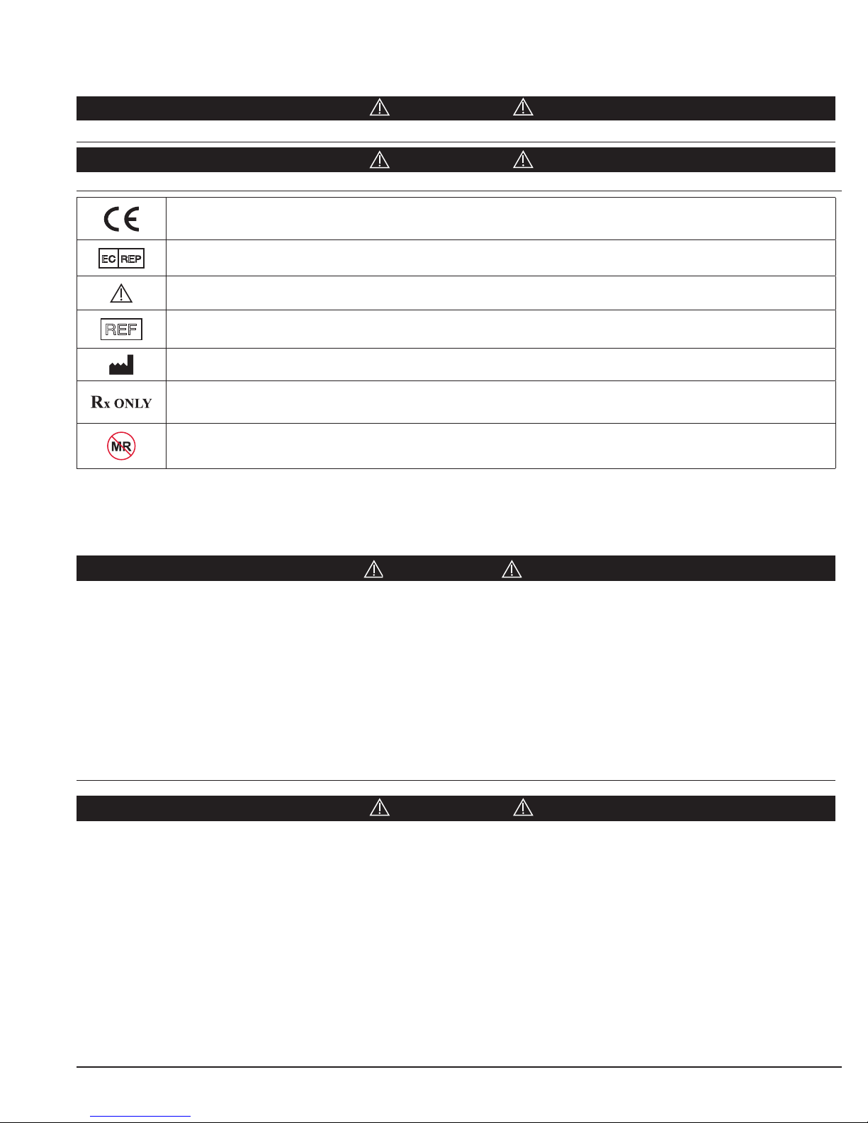
Symbols used on Labeling
EN – ENGLISH
CAUTION
Hazards which could result in equipment or property damage.
WARNING!
Hazards which could result in personal injury or death
EC REP
REF
Conforms to the European Medical Device Directive (MDD).
Authorized EC Representative in the European Community.
Attention, consult accompanying documents
Product catalog number
Manufacturer
Caution: Federal (USA) Law restricts this Device to sale by or on the order of a Licensed practitioner.
This device is not indicated for use in MR environment.
Indications For Use
The MAYFIELD® 2 Base Unit is intended to be used to support a patient during diagnostic examination and/or surgical
procedures where a rigid support between surgical table and headrest, or skull clamp is necessary, positional freedom is
required.
WARNING!
Failure to read and follow instructions and warnings furnished in this instruction manual and the instructions and warnings
included in the associated skull clamp instruction manual may result in skull pin slippage and serious patient injury, such as
scalp lacerations, skull fracture, or even death.
Failure to properly position patient and to fully tighten and secure all adjustable portions of this or any similar device may
result in skull pin slippage and serious patient injury, such as scalp laceration, skull fracture, or even death.
Monopolar electrosurgical equipment with operational voltages that exceed 3000 V may result in patient harm when this
system is used in conjunction with a skull clamp.
The user must make sure that any threaded connections are secure and starbursts have meshed (where applicable) after
adjustments are complete. Failure to do so may result in serious patient injury.
CAUTION!
Always make sure the base unit is properly secured to the operating table. The base unit must not be used if the device
appears to be damaged or functioning incorrectly.
Do not use any tools on this equipment to secure. Over-tightening any of the adjustment screws or knobs may result in
damage to the unit. If unit does not appear secure after hand-tightening, do not use the unit and contact your MAYFIELD
Representative or the MAYFIELD Service Team.
Over-extending or overloading the base unit may result in unintended movement, shortened product life and/or damage to the
unit.
Do not alter the construction of this device as it may result in serious patient injury.
Not all MAYFIELD products can be cleaned and decontaminated in the same manner as those labeled as MAYFIELD 2.
Consult the individual instructions for use (for each device) on the proper care and cleaning procedures.
2
Page 4
EN – ENGLISH
Description
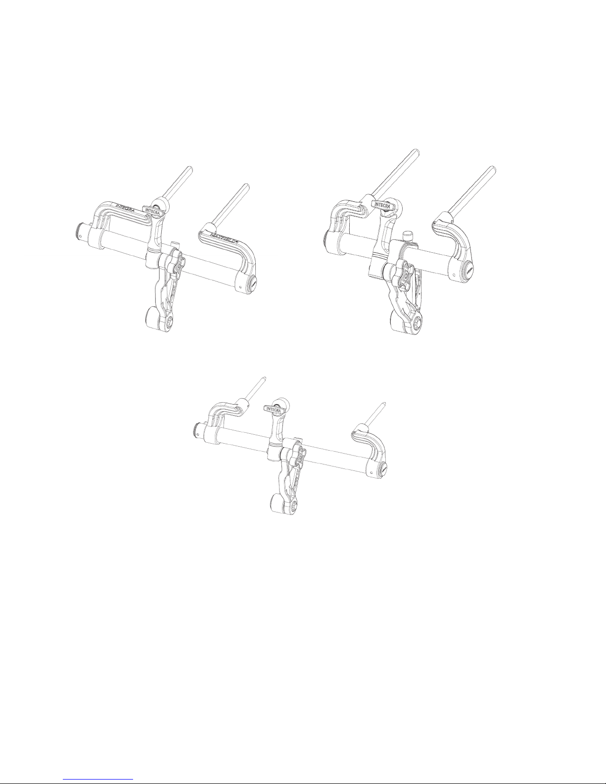
The MAYFIELD 2 Base Unit (REF A3101, A3102, A3100) is designed to provide attachment from the operating room table to
MAYFIELD Skull Clamps for rigid skeletal fixation or MAYFIELD Horseshoe Headrests for procedures where support only, and
not rigid fixation, is required. The MAYFIELD 2 Base Unit is designed for patient positioning in the prone, supine lateral or
park-bench and sitting positions. The Support Rod spacing may be readily adjusted to fit most operating room tables. No
tools are required. See Attachment to Operating Room Table for instructions to adjust the Support Rods.
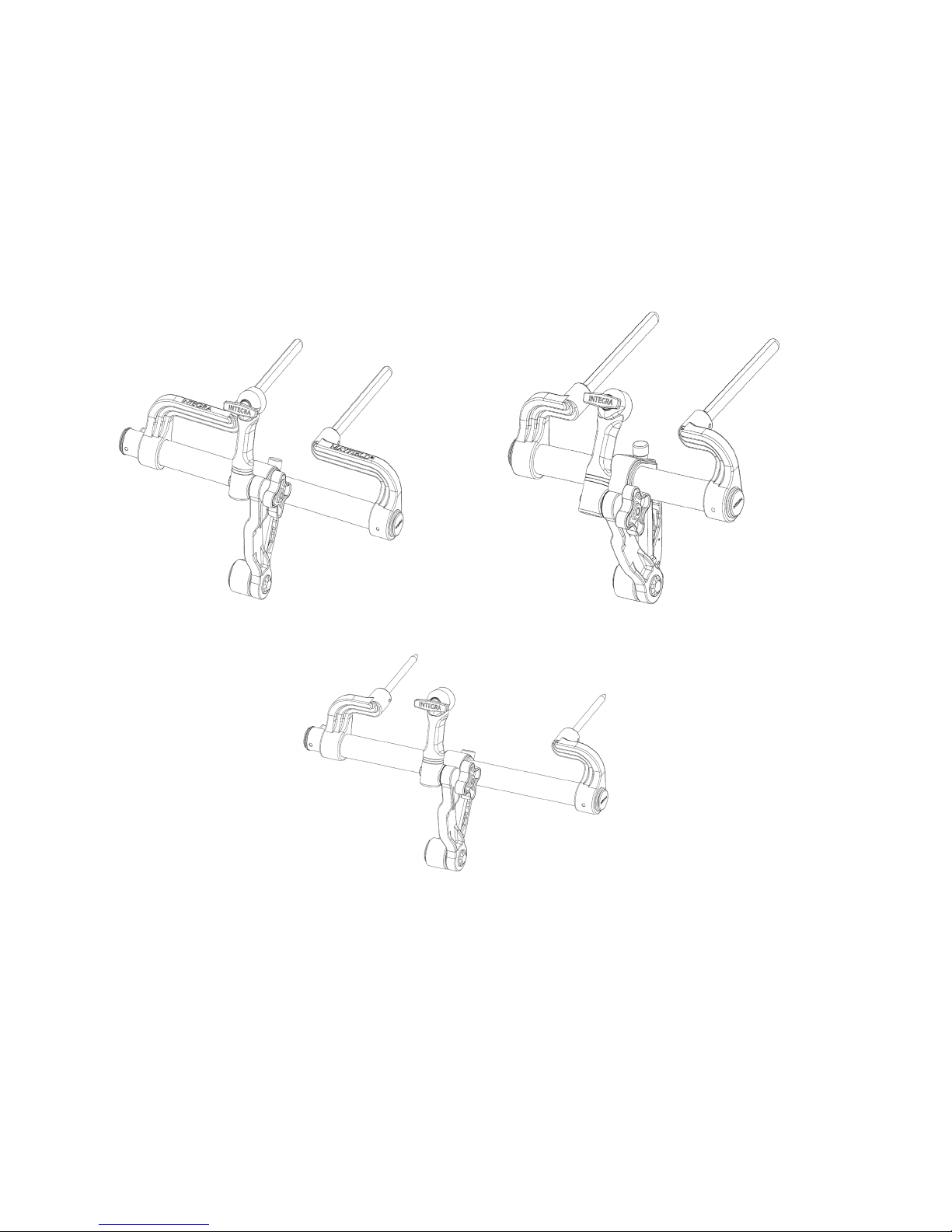
MAYFIELD 2 Base Unit, Standard A3101
MAYFIELD 2 Base Unit, Narrow A3100
MAYFIELD 2 Base Unit, International A3102
Figure 1 MAYFIELD 2 Base Unit Catalog Numbers
A Standard MAYFIELD 2 Swivel Adaptor (A3018) is an integral component of the Base Unit. A separate, optional MAYFIELD 2
Tri-Star Swivel Adaptor (A3008) is available as an accessory product when image-guided surgery (IGS) systems are used in the
procedures. The Tri-Star Swivel Adaptor provides two extra starbursts for attachment of the ancillary IGS equipment.
Each MAYFIELD 2 Base Unit purchased (A3100, A3101, or A3102) includes:
1- MAYFIELD 2 Base Unit
1- MAYFIELD 2 Swivel Adaptor (A3018)
OPTIONAL: MAYFIELD 2 Tri-Star Swivel Adaptor (A3008)
3
Page 5

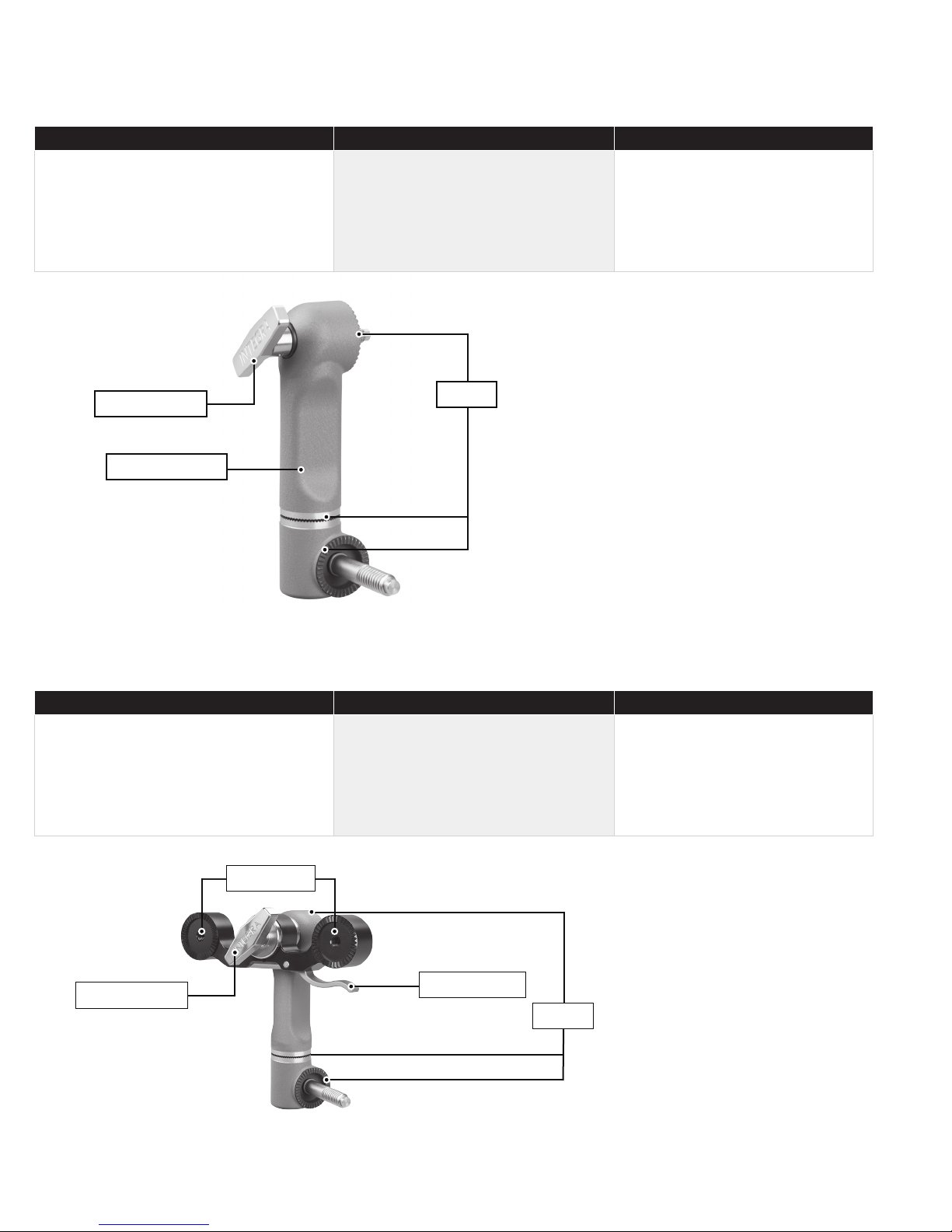
1. Left Bracket
2. Left Bracket Lock Knob
3. Connecting Tube
4. Base Handle Assembly
5. Locking Lever
6. Transitional
7. Swivel Lock Knob
8. Swvel Adaptor (A3018)
9. Headrest Lock Knob
10. Right Bracket
EN – ENGLISH
1. Transitional
2. Locking Lever
3. Latch
4. Base Handle Assembly
Figure 2A MAYFIELD 2 Base Unit Components
Figure 2B MAYFIELD 2 Base Handle Components
4
Page 6

EN – ENGLISH
Figure 3 OPTIONAL MAYFIELD 2 Tri-Star Swivel Adaptor (A3008)
The MAYFIELD 2 Base Unit is designed for use with the following equipment:
A1008 MAYFIELD General Purpose Headrest
A1011 MAYFIELD Horseshoe Headrest*
A1012 MAYFIELD Adult Horseshoe Headrest
A1015 MAYFIELD Crossbar Adaptor**
A1031 MAYFIELD (A&B) NeuroGen Adaptor
A1051 MAYFIELD Pediatric Horseshoe Headrest*
A1059 Modified MAYFIELD Skull Clamp
A1073 Posterior Cervical Support
A1108 MAYFIELD Triad Skull Clamp
A1109 MAYFIELD Horseshoe Conversion Adaptor
A1112 MAYFIELD Infinity Support System
A1113 NeuroGen Adaptor
A1114 MAYFIELD Infinity Skull Clamp
A1114A MAYFIELD Infinity Skull Clamp
A2000 MAYFIELD 2000 Skull Clamp
A3059 MAYFIELD 2 Skull Clamp
*A1109 MAYFIELD Headrest Conversion Adaptor is required for use
**A1060 Universal Side Rail Fittings is required for use
Note: Use of MAYFIELD products and accessories in conjunction with other manufacturer’s stabilization equipment is not
recommended.
5
Page 7

EN – ENGLISH
Inspection
Always inspect MAYFIELD equipment before and aer use. If a component appears damaged and/or does not seem to
function properly, do not use the device and immediately send the instrument to an authorized Integra repair center for
evaluation, repair or replacement.
Care and Maintenance
Your Integra representative will regularly perform a comprehensive inspection of your MAYFIELD equipment. In addition,
to ensure that factory-set calibrations remain in good working order, a Preventative Maintenance is required yearly at the
Integra authorized Service & Repair Center. Integra will do its best to provide comparable Service loaner equipment while
your MAYFIELD undergoes this required yearly maintenance.
To ensure proper function and to extend the life and performance of the equipment, Integra LifeSciences requires the
following:
Required Action Required Frequency
Return the device to the Integra LifeSciences Repairs department for detailed inspection
and servicing.
Request that Integra NeuroSpecialists perform routine inspections of the device
In the absence of proper care and servicing of the device, negative effects may be seen after repeated processing over time
which may lead to reduced performance.
Contact information: See the Service and Repair section for contact information on how to return your device for periodic
servicing and to request periodic inspections.
Once / year
Twice / year
Device Disposal
NOTE: Follow hospital procedures for disposal of this device.
CAUTION!
If unit is dropped or mishandled, it should be inspected for damage. (REF Inspection section of this Instruction manual). If
damage occurs, do NOT use; return the complete device immediately to Integra for inspection.
6
Page 8
EN – ENGLISH
Directions for Use
Attachment of the Base Unit to Operating Room Table:
MAYFIELD 2 Base Unit (3100) Le Bracket may be adjusted along the Connecting Tube to allow the Support Rod to
accommodate table receptacles spaced 4-1/2” to 8-1/4” (114mm to 209.5mm) apart.
MAYFIELD 2 Base Unit (3101) Le Bracket may be adjusted along the Connecting Tube to allow the Support Rod to
accommodate table receptacles spaced 5-1/8” to 8-1/4” (130mm to 209.5mm) apart.
MAYFIELD 2 Base Unit (3102) Le Bracket may be adjusted along the Connecting Tube to allow the Support Rod to
accommodate table receptacles spaced 6-5/8” to 15-3/4” (168mm to 400mm) apart.
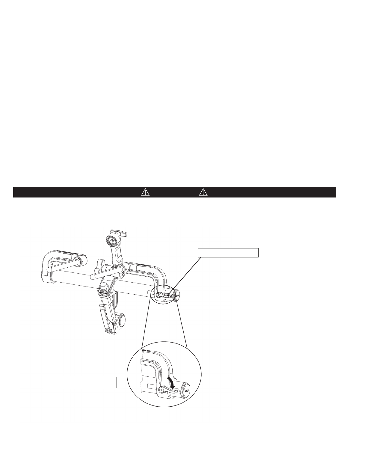
1. Locate and loosen the Left Bracket Lock Knob on the backside (See Figure 4) of the Left Bracket and slide the Left Bracket
smoothly along the the Connecting Tube until the desired width between the Support Rods is achieved.
2. Mount the Base Unit to the operating room table by aligning the two Support Rods with receptacles at the head end of
the Operating Room table, or, in the NeuroGen Adaptor or Crossbar Adaptor.
3. Tighten the Left Bracket Lock Knob to secure the Left Bracket into position.
CAUTION!
Do NOT use any tools to tighten any knobs on this device. All knobs should be hand tightened only. Use caution not to overtighten. Over-tightening may damage the device.
Le bracket lock knob
Clockwise rotation to tighten
Figure 4 Le Bracket Lock Knob
4. Secure the Base Unit Support Rods to the table by tightening the table lock knobs or the knobs on the NeuroGen
Adaptor or Crossbar Adaptor.
7
Page 9
EN – ENGLISH
Attachment of the Swivel Adaptor (A3018 or A3008) to the Base Unit
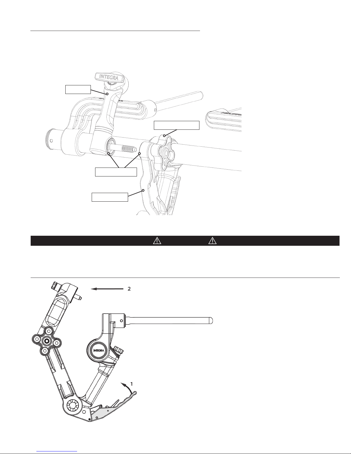
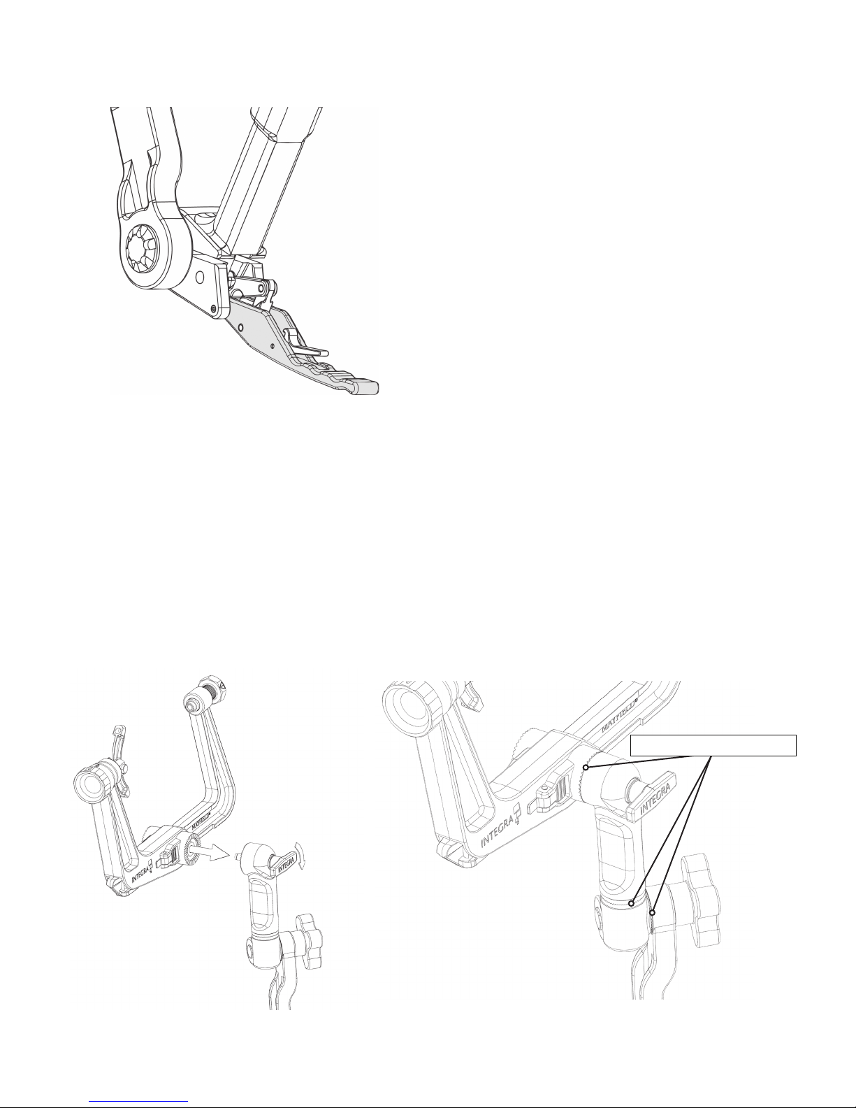
Insert screw of Swivel Adaptor into clover-shaped Swivel Lock Knob at the end of the transitional arm. Tighten by turning
Swivel Lock Knob clockwise and ensure that all starburst teeth are meshed. Do not over-tighten. No tools should be used to
attach or remove the Swivel Adaptor from the Base Unit.
Swivel
Swivel Lock Knob
Starburst Teeth
Transitional
Figure 5 Aachment of Swivel Adaptor
CAUTION!
Confirm the Base Unit stability by positioning (connected to operating table) the components as shown in Figure 6. Exert
moderate force against the Swivel Adaptor in the indicated direction shown by arrow 2 in Figure 6. No movement should be
observed at any of the joints. If movement is observed, do not use product and contact your MAYFIELD Representative or the
MAYFIELD Service Team.
Figure 6 Stability Check
8
Page 10
EN – ENGLISH
Positioning the Transitional Arm and Swivel Adaptor
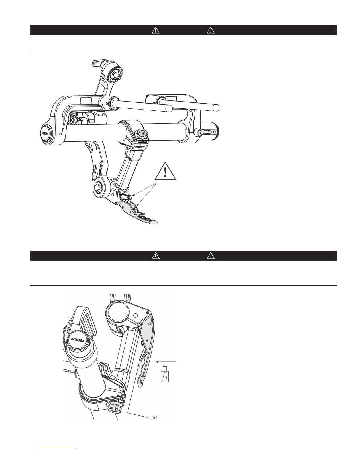
The handle is equipped with a self-latching feature. To free the Locking Lever, press the latch into the Locking Lever, the
lever will move away from its closed position.
Latch
Figure 7 Handle Self-Latching Feature
9
Page 11
EN – ENGLISH
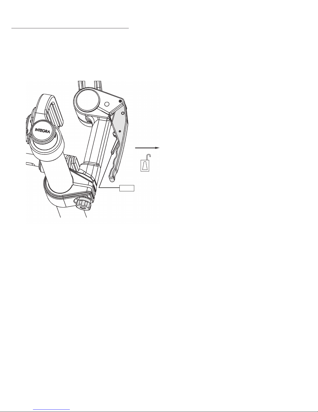
1. Open the Locking Lever to position the Transitional Arm as desired. The Locking Lever must be in the fully opened
position to perform free movement of the Transitional Arm.
Figure 8 Open Locking Lever
2. Once the Skull Clamp is applied to the patient’s skull, the surgeon will maneuver the patient to the surgical position
that is required for the procedure. With the patient in this position, the surgeon will hold the patient’s head and the
Skull Clamp and request that the Transitional Arm be brought up to the proper height for attachment of the Skull
Clamp to the Swivel Adaptor.
a) Once the Transitional Arm is at the proper height for attachment to the Skull Clamp, the mounting screw of the
large starburst on the Swivel Adaptor should be inserted into the large starburst of the Skull Clamp and turned
clockwise
and tightened. Care should be taken to maintain the position of the patient’s head as requested by the surgeon.
b) Ensure that the Skull Clamp is securely attached to the Swivel Adaptor by turning the mounting screw on the top
of the Swivel Adaptor clockwise to tighten (Figure 9A). Close the Locking Lever. Make certain that all starburst
teeth are fully meshed (where applicable) on all joints of the Base Unit after adjustments are complete.
(See Figure 9B)
Proper Meshing of Teeth (3x)
Figure 9B Proper meshing of Starburst TeethFigure 9A Attachment of Skull Clamp
10
Page 12
EN – ENGLISH
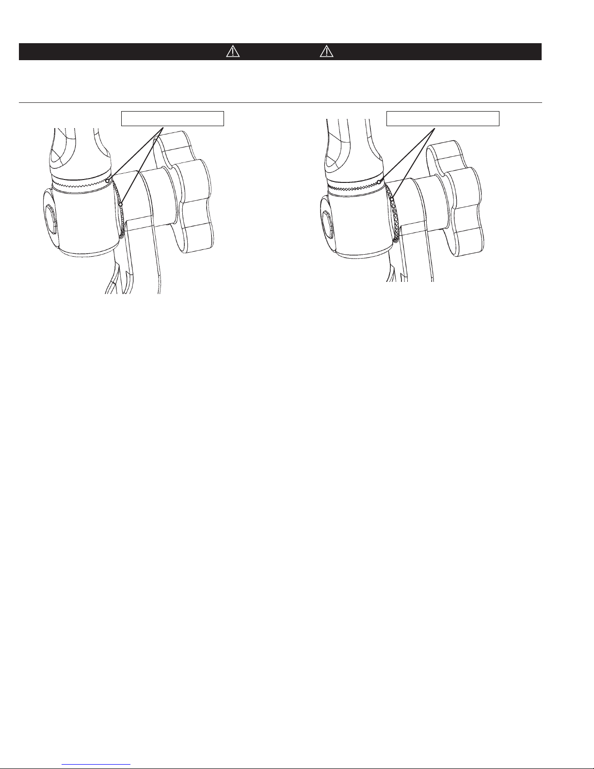
CAUTION!
Before fully tightening, always be certain that the starburst teeth of the Swivel Adaptor and other starburst fittings are the
same size and properly mesh. Failure to do so may damage fittings and/or allow unwanted movement of the patient. Figure
10 shows a typical starburst connection and proper meshing of teeth. (See Figures 10A and 10B)
Proper Meshing of Teeth
Figure 10A Proper Meshing of Teeth
Figure 10B Improper Meshing of Teeth
Improper Meshing of Teeth
(If aaching a Horseshoe Headrest, bring the Transitional Arm to the proper height. The mounting screw of the large
starburst on the Swivel Adaptor should be inserted into the large starburst of either the Horseshoe Headrest or the
Conversion Adaptor if used. Turn mounting screw on the top of the Swivel Adaptor clockwise to tighten.)
11
Page 13
EN – ENGLISH
CAUTION!
Keep fingers clear of hinge points when closing the Base Unit Locking Lever. See Figure 11 below. It is recommended that the
levers be closed using the palm of the hand.
Figure 11 Locking Mechanism
CAUTION!
Always be sure the locking mechanisms are secure after completing table adjustments. Verify that the Transitional Arm is
secured in place by confirming that the Locking Lever is engaged. Lift up on the Locking Lever WITHOUT depressing the
Latch. The Locking Lever should not be free to open.
Figure 12 Securing Locking Lever
12
Page 14

EN – ENGLISH
Cleaning of the MAYFIELD 2 Base Unit
These instructions are the recommendation of the manufacturer to ensure proper function and to extend the life and
performance of the equipment. As the equipment is reprocessed over time, many factors, including water quality used,
frequency of inspections and servicing, and method of reprocessing may impact the long term performance of the
equipment. Manual cleaning has been shown to exhibit the least amount of degradation of device performance over time,
and is therefore the recommended method of reprocessing to extend the long term performance of the equipment. The
equipment may also be reprocessed by automated cleaning and disinfection per the instructions contained in this section.
No degradation of product performance is anticipated given the device is properly cared for as recommended by the
manufacturer. This care includes inspections and periodic servicing, and avoidance of hard water where recommended. In
the absence of proper care and servicing, negative effects may be seen after repeated processing over time which may lead to
reduced performance.
Considerations:
• Follow the instructions exactly as listed in this Instruction Manual and your Hospitals procedures for
decontamination, cleaning and to reprocess medical instruments safely.
• It is important to know what method of cleaning/decontamination is needed based on what type of debris exposure
the equipment has received. This is especially important when there is the possibility of exposure to Highly
Infectious Diseases.
• This protocol has been validated for cleaning effectiveness only.
• Refer to the User Manual to disassemble the product before cleaning .
• Refer to the User Manual for further details on product use and set-up.
• The user should comply with hospital procedures and local laws and ordinances regarding reprocessing
requirements.
• Hospitals are responsible for decontaminating and packaging all loaner and demo equipment before returning to
Integra.
• Integra does not make any claims regarding the effectiveness of the decontamination processes listed in
deactivating pathogens, but rather, we are indicating that the device can withstand these procedures with minimal
loss of function.
• Please clean product using these guidelines prior to first use.
Warnings:
• Take all necessary precautions in wearing the appropriate protective equipment (eye/face, protection, gloves as
specified in the instructions provided by the cleaning agent. Clean device immediately aer each use.
• The use of highly alkaline agents may cause some components to tarnish and/or corrode. While this does not affect
the performance of the device we recommend that you use an acidic neutralizing agent immediately aer each use
to avoid the occurrence of cosmetic changes.
• Follow all instructions of the detergent, equipment washer, and autoclave manufacturer.
• Follow the detergent concentration, temperature, exposure time, material compatibility specifications, and disposal
directions of the cleaning agent as recommended by the manufacturer.
• Use only the cleaning tools mentioned in this manual. Never use metal brushes.
• Failure to follow the instructions of this document could result in damage to the equipment.
13
Page 15

MAYFIELD 2 Base Unit - A3101 (Including A3018 Swivel Adaptor)
Preparation for Cleaning and Reassembly
1. Remove skull clamp from the base unit.
2. Remove base unit from the operating room table.
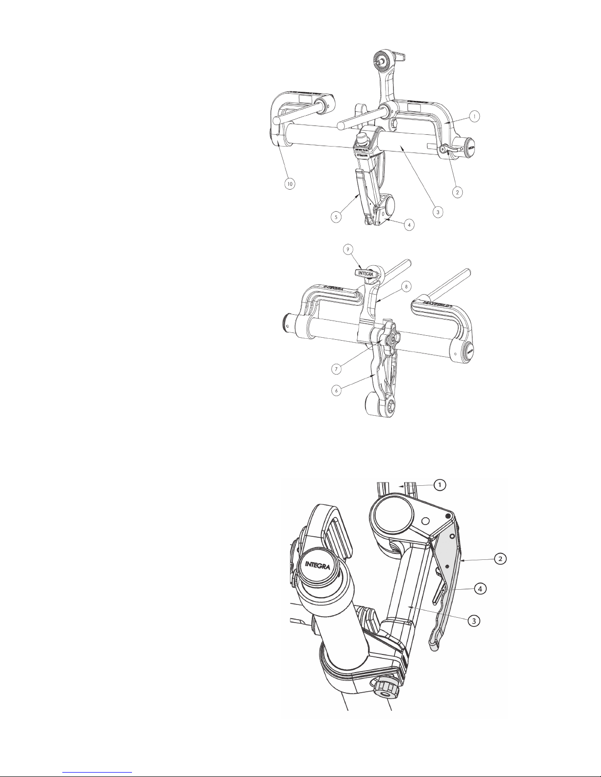
Disassembly Inspecting for cleanliness Reassembly
1– Remove swivel adaptor (1) from the base
unit (2).
2– Keep base unit (2) in the UNLOCKED
position before cleaning.
3– Do not attempt to disassamble further.
Pay close attention to:
1– Area around the locking mechanism
(3).
2– Teeth of the starburst (both sides)
(4) .
EN – ENGLISH
1– Tighten swivel adaptor (1) to the
base unit (2).
2– Store the base unit (2) with the
locking handle (5) in the closed
position.
(1) swivel adaptor
(3) locking mechanism
(4) teeth
(2) base unit
(5) locking handle
14
Page 16
EN – ENGLISH
MAYFIELD 2 Standard Swivel Adaptor - A3018
Disassembly Inspecting for cleanliness Reassembly
1– Remove swivel adaptor (1) from the base
unit (2).
2– Do not attempt to disassamble further.
Pay close attention to:
1– Teeth of the starbursts (3).
2– Area around the locking screw (2).
3– The base of the swivel adaptor for
organic debris.
N/A
(2) locking screw
(1) swivel adaptor
TriStar Swivel Adaptor - A3008
Disassembly Inspecting for cleanliness Reassembly
1– Completely remove swivel adaptor from
any components.
2– Unlock the TriStar bar (1), remove
Locking screw (2) and TriStar bar (1).
(3) teeth
Pay close attention to:
1– Teeth of the starbursts (3).
2– Area around the locking screw (2).
3– The base of the swivel adaptor for
organic debris.
1– Re-install the dual TriStar bar (1).
2– Engage the locking lever (4) on
the TriStar bar (1).
3– Insert and firmly press the torque
screw (2) in place.
(1) TriStar bar
(2) locking screw
15
(4) locking lever
(3) teeth
Page 17

EN – ENGLISH
Step 1: Decontamination after Exposure to highly infectious diseases*
When the MAYFIELD 2 System has been exposed to pathogens that resist normal disinfection methods, the product should
be handled more carefully. The following steps are recommended in accordance with the World Health Organization (WHO)
Protocol for decontamination of highly infectious diseases**:
• Keep soiled areas of the device moist. Do not apply gluteraldehyde, alcohol or formalin to the device until the
decontamination process is complete.
NOTE: Do not subject the base unit & skull clamp to automated cleaning processes until after the decontamination
procedure.
1. Remove gross debris and soil from the device components using soft cloth or paper towels. Minimize formation of
aerosols or droplets during the initial preparation of the product for decontamination.
2. Place parts in a shallow pan and add enough chlorine solution to cover the device completely.
concentration is 20,000 ppm available chlorine. See Bleach Dilution section-Appendix A.
• Allow to soak for 60 minutes.
3. Remove the devices from the bleach solution and rinse components completely with water.
• The devices may then be autoclaved at 134°C for 18 minutes to one hour.
• The devices have been verified through testing to withstand this process up to 15 times without loss of
performance.
Note: Recommended
*Highly infectious diseases including but not limited to transmissible spongiform encephalopathies (TSEs) and Creutzfeldt-Jakob disease (CJD), also known as prion diseases (reference WHO/CDS/CSR/APH/2000.3,
“WHO Infection Control Guidelines for Transmissible Spongiform Encephalopathies”, (Switzerland, March 1999) Section 1). ** Integra makes no claims that the following protocol is effective in neutralizing any specific
pathogens. The protocol is a recommendation from the World Health Organization (WHO) based on the best available evidence at the time of publication. As stated in the World Health Organization (WHO) Protocol
for Decontamination of highly infectious diseases. “Immerse [instrument] in sodium hypochlorite for 1 hour; remove and rinse with water, then transfer to open pan and heat in a gravity displacement autoclave at
(121° C) or porous load (134°C) for 1 hour.”(Reference WHO/CDS/CSR/APH/2000.3, “WHO Infection Control Guidelines for Transmissible Spongiform Encephalopathies”, (Switzerland, March 1999) pp 29).
16
Page 18

EN – ENGLISH
Step 2: Cleaning
The instrument can withstand detergents having pH values between 3 and 11. Manufacturer's instructions of the selected
detergent must be followed for this device.
NOTE: The use of highly alkaline agents can tarnish and / or corrode some components. While this does not affect the
performance of the device, we recommend using an acid neutralizing agent immediately aer each use to keep a device
looking new.
2 Cleanings are available:
• Manual Cleaning
• Automatic cleaning
Manual Cleaning
Following these steps is recommended:
1. Remove Base Unit from operating table.
2. Remove Swivel Adaptor from Base Unit.
3. The Base Unit should be thoroughly cleaned after each use. Scrub each component with a soft brush. The Base Unit
can withstand detergents that fall within pH ranges of 3-11. Clean thoroughly to remove any traces of blood and/or
debris and to prevent such blood or debris from interfering with function or movement. Rinse thoroughly with clean
water to remove all traces of detergent.
4. Dry all components with a soft dry towel.
5. After components are totally dry, inspect the unit for cleanliness.
6. Inspect all components to ensure that there is no visible organic debris or residue from cleaning agent. Repeat
process if any visible debris or residue is detected.
17
Page 19

Automatic cleaning (including thermal disinfection)
Note: The washing machine used must comply with the NF EN ISO 15883-1.
1. Disassemble devices (Refer to PREPARATION FOR CLEANING & REASSEMBLY)
2. Rinse components under warm tap water prior to placing in washer.
3. Position the device so as to prevent contact between the elements.
4. Select the cycle for instruments and perform the proper programming for the following cycle:
Phases Time (min) Water Temperature Detergent type and concentration
EN – ENGLISH
Pre-wash 1
Enzyme wash 04:00 Hot tap H2O*
04:00 Cold tap H2O N/A
Multi-tiered enzymatic
detergent with A.P.A
Wash 1
Rinse 1
Thermal rinse**
10:00 60°C Concentrated neutral pH cleaner
00:30 Hot tap H2O* N/A
02:00 82.2°C N/A
Table 1 Instrument Cycle
Step 3: Disinfection
The MAYFIELD 2 Base Unit must be thoroughly cleaned after each use. Where possible, keep the soiled areas moist until the
disinfection process can be initiated.
IMPORTANT: If the product has been exposed to persistent pathogens, do not apply gluteraldehyde, alcohol or formalin
to the device until the decontamination process is complete. After decontamination, normal cleaning processes can be
employed (see Decontamination section).
Disinfection of device components following normal usage may be achieved using the following methods:
Method 1: Thermal Rinse
• A Thermal Disinfection rinse may be added after the first rinse cycle as indicated in Table 1.
Method 2: Chemical
• Prepare a fresh solution for general disinfection (See below guidelines for bleach solution).
• With the device disassembled, place parts in a shallow pan and add enough general disinfection solution to
cover the device completely.
• Allow the parts to soak for 15 minutes.
• Rinse thoroughly with clean water.
For General Disinfection
Verify concentration of base hypochlorite is 4.5% or more
Mix 1/2 unit of bleach into 10 units of water
Table 2 Hypochlorite Bleach Mixing Guidelines
* No limit on tap water temperature
** Optional phase for disinfection of components – minimum water temperature as indicated or per washer manufacturer specifications for the thermal rinse cycle
1. Persistent pathogens are resistant to deactivation by normal disinfection procedures and may require more aggressive treatment to achieve disinfection. See guidelines in Decontamination
for recommended procedures.
section
18
Page 20

EN – ENGLISH
Disinfection (continued)
Method 3: Autoclave
• With device cleaned and disassembled, wrap components to keep clean.
• Time and temperature parameters vary widely according to the type of autoclave and packaging material. Follow
manufacturer’s instructions for loading and operating the autoclave.
• Make sure direct steam exposure to all surfaces is possible.
• Pre cycle vacuum (2psia / 14kPa) then steam disinfect at 132°C to 134°C for 4 minutes.
• Once device is removed from the autoclave, allow components to reach room temperature before reassembly,
handling, storage or use.
• Following the disinfection procedure, subject to routine cleaning (see Cleaning section).
5. Remove from the washing machine and ensure that all instruments are dried. If necessary, complete drying with a
sterile absorbent, lint-free towel.
6. Check all components to ensure they do not contain organic debris or residue of the cleaning agent. Repeat the
process if a soil is still visible. (For additionally validated cleaning cycles, refer to Appendix B)
Appendix A : Bleach Dilution
Bleach solutions produce chlorine gas. Prepare in a well-ventilated area.
NOTE: Hypochlorite potency decreases as bleach ages. Use only recently purchased bleach to prepare decontamination
solutions. Do not use pre-diluted bleach. Prepare a fresh batch for each application. Hypochlorite bleach mixing guidelines to
obtain 20,000 ppm solution:
Bleach Preparation Instructions
4.5%
5%
6%
For 4 units bleach into 5 units of water
For 2 units bleach into 3 units of water
For 1 unit bleach into 2 units of water
NOTE: The use of highly alkaline agents may cause some components to tarnish and/or corrode. While this does not affect
the performance of the device we recommend that you use an acidic neutralizing agent immediately aer each use as this
will help keep your device looking like new.
Appendix B: Additionally Validated Cleaning Cycles
Pre- Wash
Cold water from
building supply
(less than 110°or
43°C)/4min
Temperature
93°C
Hold
Time
1 or more
min.
Wash
Detergent Treatment
Alkaline
(e.g. neodisher®
SeptoClean)
Rinsing
Hot water
from building
supply/2 min
Thermal
Disinfection
Optional
(Drying
Optional)
90°C/2o
min.
50°C/7min
19
90°C
1 or more
min.
Neutral Enzymatic
(e.g. Enzol per
manufacturer's
instructions)
Hot water
from building
supply/ 2 min.
Optional
90°C/2o
min.
Page 21

EN – ENGLISH
Inspection of Components
A routine inspection of the components of the MAYFIELD 2 Base Unit should be made before each and every procedure to
assist in keeping it in good functional condition and to avoid problems the day of surgery. This check should include the
following:
1. Check to see that all the components of the base unit are available for assembly. Use the Inspection section of this
Instruction Manual for a complete list of components. ALL components must be available and ready for assembly or
the Base Unit should not be used.
2. Check the adjustment of the base locking handles by following these steps.
a. Attach the Base Unit to an OR table and lock in place as shown earlier in this manual.
b. Confirm that the handle is holding as it should.
c. If the handle is not holding under pressure, use the following directions to adjust the handle.
3. Test the operation of the handle after adjustment. Follow the same instructions as outlined earlier in this manual to
verify that the handle is going to hold when force is exerted against it.
4. Check the other components of the Base Unit for function.
a. Check that the Locking Handle assembly will slide easily from one side of the Horizontal Bar to the other.
b. Verify that the Left Bracket is securely fastened and does not move.
c. Fully engage the Locking Knob on the Swivel to make sure that it completely engages the starburst teeth and does
not swivel or move in either direction.
d. With the Locking Lever locked and the Swivel Knob tightened, the total Base Unit should be locked in place and no
movement should be seen.
e. If any movement is observed, re-tighten the knob and adjust the Locking Lever.
5. Perform visual check of all components (Start at on side of the Base Unit and systematically review each component as
you make your way to the other side to assure that you do not miss a component).
a. Check all connections to be free of debris that might impair the function of that component or the one that
connects to that component.
b. Examine all components for cracks on all surfaces.
20
Page 22

EN – ENGLISH
Integra Standard Warranty
INTEGRA warrants to the original purchaser only that each new MAYFIELD product is free from manufacturing defects in
material and workmanship under normal use and service for a period of one year (except as otherwise expressly provided as
to accessory items) from the date of delivery by INTEGRA to the first purchaser, but in no event beyond the expiration date
stated on any product labeling.
• Surgical instruments are guaranteed to be free from defects in material and workmanship when maintained
and cleaned properly and used normally for their intended purpose.
• Any covered product that is placed by INTEGRA under a lease, rental or installment purchase agreement and that
requires repair service during the term of such placement agreement shall be repaired in accordance with the terms
of such agreement.
If any covered defect occurs during the warranty period or term of such placement agreement, the purchaser should
communicate directly with INTEGRA’s home office. If purchaser seeks to invoke the terms of this warranty, the product must
be returned to INTEGRA at its home office. The defective product should be returned promptly, properly
packaged and postage prepaid. Loss or damage in return shipment to INTEGRA shall be at CUSTOMER’s risk.
INTEGRA’s sole responsibility under this warranty shall be repair or replacement, at INTEGRA’s sole discretion
at INTEGRA’s expense, subject to the terms of this warranty and applicable agreements.
IN NO EVENT SHALL INTEGRA BE LIABLE FOR ANY INCIDENTAL, INDIRECT, CONSEQUENTIAL OR PUNITIVE DAMAGES
IN CONNECTION WITH THE ACQUISITION OR USE OF ANY INTEGRA PRODUCT. Further, this warranty shall not apply to,
and INTEGRA shall not be responsible for, any loss arising in connection with the purchase or use of any INTEGRA product
that has been repaired by anyone other than an authorized INTEGRA service representative or altered in any way so as, in
INTEGRA’s judgment, to affect its stability or reliability, or which has been subject to misuse, negligence or accident, or
which has been used otherwise than in accordance with the instructions furnished by INTEGRA. THIS LIMITED WARRANTY
IS EXCLUSIVE AND IN LIEU OF ALL OTHER WARRANTIES, EXPRESS OR IMPLIED, AND OF ALL OTHER OBLIGATIONS OR
LIABILITIES ON INTEGRA’S PART, AND INTEGRA NEITHER ASSUMES NOR AUTHORIZES ANY REPRESENTATIVE OR OTHER
PERSON TO ASSUME FOR IT ANY OTHER LIABILITY IN CONNECTION WITH INTEGRA’S
PRODUCTS.
INTEGRA DISCLAIMS ALL OTHER WARRANTIES, EXPRESS OR IMPLIED INCLUDING ANY IMPLIED WARRANTY
OF MERCHANTABILITY OR OF FITNESS FOR A PARTICULAR PURPOSE OR APPLICATION OR WARRANTY OF QUALITY AS
WELL AS ANY EXPRESS OR IMPLIED WARRANTY TO PATIENTS. No warranty or guarantee may be created by any act
or statement nor may this Standard Warranty be modified in any way, except as a result of a writing signed by an officer
of INTEGRA. These limitations on the creation or modification of this warranty may not be waived or modified orally
or by any conduct.
Service and Repair
For service and repairs outside the United States, contact your local authorized Integra representative.
Within the United States, send all instruments for service or repair to:
Integra
4900 Charlemar Drive, Building A
Cincinnati, Ohio 45227
(Always include the purchase order number or RMA number and a written description of the problem)
Or phone: 877-444-1114
21
Page 23

EN – ENGLISH
0086
Availability of these products might vary from a given country or region to another, as a result of specific local regulatory approval or clearance requirements for sale in such country or region.
n
Always refer to the appropriate instructions for use for complete clinical instructions.
n
Non contractual document. The manufacturer reserves the right, without prior notice, to modify the products in order to improve their quality.
n
Warning: Applicable laws restrict these products to sale by or on the order of a physician.
Additional information for EMEA Customers only:
Produc ts mentione d in this document are CE class I, IIa, IIb or III dev ices. Contac t Integra should you need any additional info rmation on devices clas sification. All the medical device s
mentioned on this document are CE mar ked according to European council directive 93/42/EEC on me dical devices an d its relatives, unles s specific ally identified as “NOT C E MARKED”.
For more information or to place an order, please contact:
United States, Canada, Asia, Pacific, Latin America
USA 800-654-2873
International +1 609-936-5400
integralife.com/contact
Europe, Middle-East, Africa
International +33 (0)4 37 47 59 50
Benelux +32 (0)2 257 4130
France +33 (0)4 37 47 59 10
Switzerland +41 (0)22 721 23 00
United Kingdom +44 (0)1 264 345 781
integralife.eu/contact
U.S. Patents 7,552,492; 8, 683, 630
Integra and the Integra logo are registered trademarks of Integra Life Sciences Corporation in the United States and/or other countr ies. MAYFIELD is a regis tered trademark of SM USA Inc
and is used by Integr a Lifescience s Corporation under license. Neodisher is a trademark of Chemische Fabrik Dr. Weiger t GHBH & Co. KB Enzol is a trademark of Johnson & Johnson.
©2017 Integra LifeSciences Corporation. All rights reser ved. 451A3100 Rev. H 01/17 0649598-1
n 888-980-7742 fax
n +1 609-750-4259 fax
n +33 (0)4 37 47 59 25 fax
n +32 (0)2 253 2466 fax
n +33 (0)4 37 47 59 29 fax
n +41 (0)22 721 23 99 fax
n +44 (0)1 264 363 782 fax
Manufacturer:
Integra LifeSciences Corporation
4900 Charlemar Drive, Bldg. A
Cincinnati, Ohio 45227
EC REP
Integra LifeSciences Services (France) SAS
Immeuble Séquoia 2
Parc technologique de la Porte des Alpes
69800 Saint Priest
n
USA
n
97 allée Alexandre Borodine
n
FRANCE
22
Page 24

FR – FRANÇAIS
23
Page 25

Unité de base MAYFIELD® 2
(A3100, 3101, 3102)
FR – FRANÇAIS
Mode d’emploi
24
Page 26

FR – FRANÇAIS
2525
Page 27
0123
Symboles indiqués sur les étiquees
Dangers risquant de produire des dégâts matériels.
Dangers risquant de produire des blessures corporelles ou le décès.
FR – FRANÇAIS
ATTENTION
AVERTISSEMENT
EC REP
REF
Conforme à la directive européenne relative aux dispositifs médicaux (DM).
Mandataire établi dans la Communauté européenne.
Attention, consulter la documentation jointe.
Numéro de référence produit
Fabricant
Attention : Selon la loi fédérale américaine, ce dispositif ne peut être vendu que par un praticien autorisé ou sur son
ordonnance.
Ce dispositif n’est pas indiqué pour être utilisé dans un environnement IRM.
Indications
L’unité de base MAYFIELD® 2 est prévue pour soutenir le patient au cours d’examens de diagnostic et/ou d’interventions
chirurgicales, lorsqu’un support rigide entre la table d'opération et une têtière ou un clameau crânien est nécessaire, et que la
souplesse du positionnement est requise.
AVERTISSEMENT
Tout manquement à lire et à observer les instructions et avertissements donnés dans ce mode d’emploi ainsi que les instructions et
avertissements donnés dans le mode d’emploi du clameau crânien associé, risque d’entraîner le glissement des pointes crâniennes
et des lésions graves chez le patient, notamment des lacérations du cuir chevelu, une fracture du crâne ou même le décès.
Tout manquement à positionner correctement le patient et à serrer et fixer complètement toutes les parties ajustables de ce
dispositif ou des dispositifs similaires risque d’entraîner le glissement des pointes crâniennes et des lésions graves chez le
patient, notamment des lacérations du cuir chevelu, une fracture du crâne ou même le décès.
Le matériel électrochirurgical monopolaire dont la tension de fonctionnement est supérieure à 3 000 V risque de nuire au
patient quand ce système est utilisé avec un clameau crânien.
L’utilisateur doit vérifier que les raccords filetés sont bien serrés et que les dentures radiales sont engagées (si applicable) après
avoir terminé les réglages. Tout manquement à observer cet avertissement risque d’entraîner des lésions graves chez le patient.
ATTENTION
Toujours vérifier que l’unité de base est solidement fixée à la table d’opération. Ne pas utiliser l’unité de base si elle est
endommagée ou ne fonctionne pas correctement.
N’utiliser aucun outil pour la fixation de ce matériel. Un serrage excessif des vis ou molettes de réglage risque d’endommager
l’unité. Si l’unité ne paraît pas solidement fixée après le serrage manuel, ne pas l’utiliser et contacter le représentant
MAYFIELD ou l’équipe de service après-vente MAYFIELD.
La surextension ou la surcharge de l’unité de base risque d’entraîner des déplacements involontaires, d’écourter la durée de
vie du produit et/ou d’endommager l’unité.
Ne pas modifier la construction de ce dispositif sous risque d’entraîner des lésions graves chez le patient.
26
Page 28
FR – FRANÇAIS
Tous les produits MAYFIELD ne peuvent pas nécessairement tous être nettoyés et décontaminés de la même façon que
les produits MAYFIELD 2. Consulter le modes d’emploi individuel (pour chaque dispositif) quant aux procédures correctes
d’entretien et de nettoyage.
Description
L’unité de base MAYFIELD 2 (REF A3101, A3102, A3100) est conçue assurer pour la fixation entre la table d’opération et les
clameaux crâniens MAYFIELD (pour une fixation squelettique rigide) ou les têtières fer à cheval MAYFIELD (pour les interventions
nécessitant uniquement un support et non une fixation rigide). L’unité de base MAYFIELD 2 est conçue pour le positionnement
du patient en décubitus ventral, en décubitus latéral ou en position Park Bench ou assise. L’espacement de la tige de support
peut être facilement réglée pour s’adapter à la plupart des tables d’opération. Aucun outil n’est requis. Consulter la section
« Fixation de l’unité de base à la table d’opération » pour des directives sur le réglage des tiges de support.
Unité de base MAYFIELD 2, Standard A3101
Unité de base MAYFIELD 2, étroite A3100
Unité de base MAYFIELD 2, internationale A3101
Figure 1 Unité de base MAYFIELD 2 – Numéros de référence
Un adaptateur pivotant MAYFIELD 2 standard (A3018) est un composant intégral de l’unité de base. Un adaptateur pivotant
Tri-Star MAYFIELD 2 (A3008) séparé, en option, est disponible en tant qu’accessoire quand des systèmes de chirurgie
assistée par ordinateur (CAO) sont utilisés lors des interventions. L’adaptateur pivotant Tri-Star offre deux dentures radiales
supplémentaires pour la fixation du matériel de CAO auxiliaire.
Chaque unité de base MAYFIELD 2 achetée (A3100, A3101 ou A3102) comprend :
1- Unité de base MAYFIELD 2
1- Adaptateur pivotant MAYFIELD 2 (A3018)
EN OPTION : Adaptateur pivotant Tri-Star MAYFIELD 2 (A3008)
27
Page 29
1. Support de gauche
2. Bouton de verrouillage du support de gauche
3. Tube connecteur
4. Ensemble de poignée de la base
5. Levier de blocage
6. Bras de transition
7. Molette de verrouillage du pivot
8. Adaptateur pivotant (A3018)
9. Bouton de verrouillage de la têtière
10. Support de droite
FR – FRANÇAIS
1. Bras de transition
2. Levier de blocage
3. Loquet
4. Ensemble de poignée de la base
Figure 2A Composants de l’unité de base MAYFIELD 2
Figure 2B Composants de la poignée de la base MAYFIELD 2
28
Page 30

FR – FRANÇAIS
Figure 3 Adaptateur pivotant Tri-Star MAYFIELD 2 (A3008) EN OPTION
L’unité de base MAYFIELD 2 est conçue pour être utilisée avec le matériel suivant :
Têtière à usage général MAYFIELD A1008
Têtière fer à cheval MAYFIELD A1011*
Têtière fer à cheval adulte MAYFIELD A1012
Adaptateur de barre transversale MAYFIELD A1015**
Adaptateur NeuroGen MAYFIELD A1031 (A et B)
Têtière fer à cheval pédiatrique MAYFIELD A1051*
Clameau crânien MAYFIELD modifié A1059
Support cervical postérieur MAYFIELD A1073
Clameau crânien MAYFIELD Triad A1108
Adaptateur de conversion pour fer à cheval MAYFIELD A1109
Système de support MAYFIELD Infinity A1112
Adaptateur NeuroGen A1113
Clameau crânien MAYFIELD Infinity A1114
Clameau crânien MAYFIELD Infinity A1114A
Clameau crânien 2000 MAYFIELD A2000
Clameau crânien MAYFIELD 2 A3059
*Adaptateur de conversion pour fer à cheval MAYFIELD A1109 requis.
**Raccords pour rail latéral universel A1060 requis.
Remarque : L’utilisation des produits et accessoires MAYFIELD avec le matériel de stabilisation d’autres fabricants n’est pas
recommandée.
29
Page 31

FR – FRANÇAIS
Inspection
Toujours inspecter le matériel MAYFIELD avant et après l’utilisation. Si un composant est endommagé et/ou ne fonctionne
pas correctement, ne pas utiliser le dispositif et le renvoyer immédiatement à un centre de réparation Integra agréé pour
évaluation, réparation ou remplacement.
Soins et entretien
Votre représentant Integra procède à l’inspection compréhensive régulière de votre matériel MAYFIELD. De plus, pour assurer
le bon fonctionnement des étalonnages réglés en usine, un service de maintenance préventive annuelle est requis dans un
centre de service après-vente et de réparation Integra agréé. Integra s’efforce d’assurer le prêt de matériel de remplacement
pendant le service après-vente annuel requis de votre matériel MAYFIELD.
Pour garantir le bon fonctionnement et prolonger la durée de vie et les performances du matériel, Integra LifeSciences exige
les mesures de maintenance suivantes :
Action requise Fréquence requise
Retour du dispositif au service Integra LifeSciences Repairs pour l’inspection détaillée et
l’entretien.
Inspection routinière du dispositif par le personnel Integra NeuroSpecialist
Si l’entretien et la maintenance du dispositif ne sont pas assurés, des effets délétères risquent d’être constatés à la longue
après des traitements répétés, ce qui peut conduire à la réduction des performances.
Informations de contact : Consulter la section « Service après-vente et réparation » pour obtenir les coordonnées à utiliser
pour le retour du dispositif dans le cadre du service après-vente périodique et de la demande d’inspections périodiques.
Une fois par an
Deux fois par an
Élimination du dispositif
REMARQUE : Observer le protocole hospitalier pour l’élimination de ce dispositif.
ATTENTION
Si le dispositif fait l’objet d’une chute ou d’une manipulation abusive, l’inspecter pour s’assurer qu’il n’a pas été endommagé.
(Consulter la section « Inspection » de ce manuel.) En présence d’endommagement, ne PAS utiliser le dispositif ; retourner
immédiatement le dispositif au complet à Integra pour inspection.
30
Page 32

FR – FRANÇAIS
Instructions d’utilisation
Fixation de l’unité de base à la table d’opération :
Le support de gauche de l’unité de base MAYFIELD 2 (3100) peut être réglé le long du tube connecteur pour permere à la
tige de support d’accueillir des logements de table espacés de 114 mm à 209,5 mm.
Le support de gauche de l’unité de base MAYFIELD 2 (3101) peut être réglé le long du tube connecteur pour permere à la tige
de support d’accueillir des logements de table espacés de 130 mm à 209,5 mm.
Le support de gauche de l’unité de base MAYFIELD 2 (3102) peut être réglé le long du tube connecteur pour permere à la
tige de support d’accueillir des logements de table espacés de 168 mm à 400 mm.
1. Situer et desserrer le bouton de verrouillage du support de gauche, qui se trouve au dos (voir Figure 4) du support de
gauche, et glisser doucement le support de gauche le long du tube connecteur jusqu’à ce que la largeur voulue soit
obtenue entre les tiges de support.
2. Monter l’unité de base sur la table d’opération en alignant les deux tiges de support avec les logements du côté tête de
la table d’opération, ou dans l’adaptateur NeuroGen ou l’adaptateur de barre transversale.
3. Serrer le bouton de verrouillage du support de gauche pour fixer le support de gauche en position.
ATTENTION
NE PAS utiliser d’outils pour serrer les boutons sur ce dispositif. Tous les boutons doivent être serrés uniquement à la main.
Veiller à ne pas serrer excessivement. Un serrage excessif risque d’endommager le dispositif.
Bouton de verrouillage du support de gauche
Tourner dans le sens
horaire pour serrer
Figure 4 Bouton de verrouillage du support de gauche
4. Fixer les tiges de support de l’unité de base à la table en serrant les boutons de verrouillage de la table ou les boutons de
l’adaptateur NeuroGen ou de l’adaptateur de barre transversale.
31
Page 33

FR – FRANÇAIS
Fixation de l’adaptateur pivotant (A3018 ou A3008) à l’unité de base
Insérer la vis de l’adaptateur pivotant dans la molette de verrouillage du pivot, en forme de trèfle, située à l’extrémité du bras
de transition. Serrer en tournant la molette de verrouillage du pivot dans le sens horaire et s’assurer que toutes les dentures
radiales sont engagées les unes dans les autres. Ne pas trop serrer. N’utiliser aucun outil pour fixer ou retirer l’adaptateur
pivotant de l’unité de base.
Pivot
Molee de
verrouillage du pivot
Dentures radiales
Bras de transition
Figure 5 Fixation de l’adaptateur pivotant
ATTENTION
Confirmer la stabilité de l’unité de base en positionnant les composants (connectés à la table d’opération) comme illustré à
la Figure 6. Exercer une force modérée contre l’adaptateur pivotant, dans le sens indiqué par la flèche 2 à la Figure 6. Aucun
mouvement ne doit être observé au niveau des articulations. Si un mouvement est observé, ne pas utiliser le produit et
contacter le représentant MAYFIELD ou l’équipe de service après-vente MAYFIELD.
Figure 6 Contrôle de la stabilité
32
Page 34

FR – FRANÇAIS
Positionnement du bras de transition et de l’adaptateur pivotant
La poignée est dotée d’un mécanisme autobloquant. Pour dégager le levier de verrouillage, enfoncer le loquet dans le
levier de verrouillage ; le levier se déplacera de sa position fermée.
Loquet
Figure 7 Mécanisme autobloquant de la poignée
33
Page 35

FR – FRANÇAIS
1. Ouvrir le levier de verrouillage afin de positionner le bras de transition de la façon voulue. Le levier de verrouillage doit
être complètement ouvert pour que le bras de transition puisse se déplacer librement.
Figure 8 Ouvrir le levier de verrouillage
2. Une fois que le serre-crâne est placé sur le crâne du patient, le chirurgien placera le patient dans la position
chirurgicale requise pour la procédure. Avec le patient dans cette position, le chirurgien maintient la tête du patient
et le clameau crânien, et demande à ce que le bras de transition soit ramené à la hauteur requise pour fixer le clameau
crânien à l’adaptateur pivotant.
a) Une fois que le bras de transition est à la bonne hauteur pour la fixation au clameau crânien, la vis de montage
de la grande denture radiale sur l’adaptateur pivotant doit être insérée dans la grande denture radiale du clameau
crânien, puis tournée dans le sens horaire et serrée. Veiller à maintenir la position de la tête du patient requise
par le chirurgien.
b) S’assurer que le clameau crânien est solidement fixé à l’adaptateur pivotant en tournant la vis de montage en
haut de l’adaptateur pivotant dans le sens horaire pour serrer (voir Figure 9A). Fermer le levier de verrouillage.
Quand tous les réglages sont terminés, s’assurer que toutes les dentures radiales sont complètement engagées
les unes dans les autres (si applicable) au niveau de toutes les articulations de l’unité de base.
(Voir Figure 9B)
Engagement correct
des dentures (3x)
Figure 9B Engagement correct des dentures radialesFigure 9A Fixation du clameau crânien
34
Page 36

FR – FRANÇAIS
ATTENTION
Avant se serrer complètement, toujours vérifier que les dentures radiales de l’adaptateur pivotant et des autres composants
sont de la même taille et correctement engagées. Le non respect de cette consigne risque d’endommager les raccords et/ou
de permettre un mouvement involontaire du patient. La Figure 10 montre un raccordement radial typique et l’engagement
correct des dentures. (Voir Figures 10A et 10B)
Engagement correct des dentures
Figure 10A Engagement correct des dentures
Figure 10B Engagement incorrect des dentures
Engagement incorrect des dentures
(Pour fixer la têtière fer à cheval, ramener le bras de transition à la hauteur voulue. La vis de montage de la grande denture
radiale sur l’adaptateur pivotant doit être insérée dans la grande denture radiale de la têtière fer à cheval ou de l’adaptateur de
conversion, le cas échéant. Tourner la vis de montage en haut de l’adaptateur pivotant dans le sens horaire pour serrer.)
35
Page 37

FR – FRANÇAIS
ATTENTION
Éloigner les doigts des charnières en fermant le levier de verrouillage de l’unité de base. Voir la Figure 11 ci-dessous. Il est
conseillé de fermer les leviers en utilisant la paume de la main.
Figure 11 Mécanisme de verrouillage
ATTENTION
Toujours s’assurer que les mécanismes de verrouillage sont fixés après avoir terminé les réglages de la table. Vérifier que le
bras de transition est fixé en place en confirmant que le levier de verrouillage est engagé. Soulever le levier de verrouillage
SANS enfoncer le loquet. Le levier de verrouillage ne doit pas pouvoir s’ouvrir.
Figure 12 Fixation du levier de verrouillage
Loquet
36
Page 38

FR – FRANÇAIS
Neoyage de l’unité de base MAYFIELD 2
Ces directives sont la recommandation du fabricant pour garantir le bon fonctionnement et prolonger la durée de vie et
les performances du matériel. À la longue après des retraitements répétés, plusieurs facteurs, y compris la qualité de l’eau
utilisée, la fréquence des inspections et de l’entretien, et la méthode de retraitement, peuvent impacter les performances
à long terme du matériel. Il a été prouvé que le nettoyage manuel présente la plus faible dégradation des performances
du dispositif dans le temps, et celui-ci constitue donc la méthode de retraitement recommandée pour prolonger les
performances à long terme du matériel. Le matériel peut également être retraité par nettoyage et désinfection automatisés,
conformément aux directives dans cette section. Aucune dégradation des performances du produit n’est anticipée si le
dispositif est correctement entretenu conformément aux recommandations du fabricant. Cet entretien inclut des inspections
et une maintenance périodiques, et l’évitement d’eau calcaire quand cela est conseillé. Si l’entretien et la maintenance ne
sont pas assurés, des effets délétères risquent d’être constatés à la longue après des traitements répétés, ce qui peut conduire
à une réduction des performances.
Considérations :
• Suivre les directives exactement comme indiqué dans ce mode d’emploi ainsi que vos procédures hospitalières pour
la décontamination, le nettoyage et le retraitement en toute sécurité des instruments médicaux.
• Il est important de savoir quelle méthode de nettoyage/décontamination est nécessaire en fonction du type
d'exposition aux débris auquel l'équipement a été soumis. Ceci est particulièrement important lorsqu’il existe un
risque d'exposition à des maladies très infectieuses.
• Ce protocole a uniquement été validé pour l'efficacité du nettoyage.
• Consulter le manuel d’utilisation pour le démontage du produit avant de le nettoyer.
• Consulter le manuel d’utilisation pour obtenir plus de détails sur l'utilisation et l’installation du produit.
• L'utilisateur doit se conformer aux procédures de l'établissement hospitalier et à la réglementation locale
concernant les obligations en matière de reconditionnement.
• Les hôpitaux doivent s'assurer de la décontamination et du conditionnement de tous les articles en prêt ou de
démonstration avant de les renvoyer à Integra.
• Integra ne fait aucune revendication quant à l'efficacité des procédés de décontamination cités pour la
désactivation des agents pathogènes, mais indique plutôt que le dispositif est capable de subir ces procédés avec
une perte minimale de la fonction.
• Nettoyer le produit en suivant ces directives avant la première utilisation.
Avertissements :
• Prendre toutes les précautions nécessaires pour porter l'équipement de protection approprié (protection des yeux/
du visage, gants) comme spécifié dans les instructions fournies avec le produit nettoyant. Nettoyer le dispositif
immédiatement après chaque utilisation.
• L'utilisation de produits fortement alcalins peut provoquer l’oxydation et/ou la corrosion de certains composants.
Bien que cela n’affecte pas les performances du dispositif, il est recommandé d'utiliser un produit qui neutralise
l’acide immédiatement après chaque utilisation pour éviter toute altération cosmétique.
• Suivre toutes les instructions des fabricants du détergent, du laveur de matériel et de l’autoclave.
• Suivre les spécifications du fabricant relatives à la concentration de détergent, la température, le temps
d'exposition, la compatibilité des matériaux et les directives d'élimination du produit de nettoyage.
• Utiliser uniquement les outils de nettoyage mentionnés dans ce manuel. Ne jamais utiliser de brosses métalliques.
• Le non respect des consignes données dans ce document peut entraîner l’endommagement du matériel.
37
Page 39

Unité de base MAYFIELD 2 - A3101 (avec l’adaptateur pivotant A3018)
Préparation avant le neoyage et le remontage
1. Retirer le clameau crânien de l'unité de base.
2. Retirer l'unité de base de la table d'opération.
Démontage Vérification de la propreté Remontage
1– Retirer l’adaptateur pivotant (1) de
l'unité de base (2).
2– Conserver l’unité de base (2) dans la
position DÉVERROUILLÉE
avant le nettoyage.
3– Ne pas essayer de démonter davantage
les composants.
Veiller en particulier aux points suivants :
1– Zone autour du mécanisme de
verrouillage (3).
2– Dentures radiales (des deux côtés)
(4).
FR – FRANÇAIS
1– Serrer l’adaptateur pivotant (1) sur
l'unité de base (2).
2– Ranger l'unité de base (2) avec le
levier de verrouillage (5) dans la
position fermée.
(1) adaptateur pivotant
(3) mécanisme de verrouillage
(4) dentures
(2) unité de base
(5) levier de verrouillage
38
Page 40

FR – FRANÇAIS
Adaptateur pivotant standard MAYFIELD 2 - A3018
Démontage Vérification de la propreté Remontage
1– Retirer l’adaptateur pivotant (1) de
l'unité de base (2).
2– Ne pas essayer de démonter davantage
les composants.
Veiller en particulier aux points suivants :
1– Dentures radiales (3).
2– Zone autour de la vis de blocage (2).
3– Base de l'adaptateur pivotant pour
la présence de débris organiques.
S.O.
(2) vis de blocage
(1) adaptateur pivotant
(3) dentures
Adaptateur pivotant Tri-Star - A3008
Étape 1 : Décontamination après exposition à des maladies hautement infectieuses*
Démontage Vérification de la propreté Remontage
1– Retirer complètement l’adaptateur
pivotant de tous les composants.
2– Déverrouiller la barre de l’adaptateur
Tri-Star (1), retirer la vis de blocage (2)
et la barre de l’adaptateur Tri-Star (1).
Veiller en particulier aux points suivants :
1– Dentures radiales (3).
2– Zone autour de la vis de blocage (2).
3– Base de l'adaptateur pivotant pour la
présence de débris organiques.
1– Réinstaller la barre double de
l’adaptateur Tri-Star (1).
2– Base de l'adaptateur pivotant
pour la présence de débris
organiques.
3– Insérer et enfoncer fermement en
place la vis de couple (2).
(1) barre de l'adaptateur Tri-Star
(2) vis de blocage
39
(4) levier de verrouillage
(3) dentures
Page 41

FR – FRANÇAIS
Étape 1 : Décontamination après exposition à des maladies hautement infectieuses*
Lorsque le système MAYFIELD 2 a été exposé à des agents pathogènes qui résistent aux méthodes de désinfection standard,
le produit doit être manipulé avec plus de soin. Les étapes suivantes sont recommandées conformément au protocole de
l'Organisation mondiale de la Santé (OMS) pour la décontamination des maladies hautement infectieuses** :
• Conserver les zones souillées du dispositif à l’état humide. Ne pas appliquer de glutaraldéhyde, d'alcool ou de
formol sur le dispositif avant que le procédé de décontamination ne soit terminé.
REMARQUE : Ne soumettre l'unité de base et le clameau crânien à des procédés de nettoyage automatisés qu'après le
procédé de décontamination.
1. Éliminer les débris et souillures visibles des composants du dispositif à l'aide d’un linge doux ou de serviettes en
papier. Réduire au minimum la formation d'aérosols ou de gouttelettes lors de la préparation initiale du produit avant
la décontamination.
2. Placer les pièces dans un bac peu profond et ajouter suffisamment de solution de chlore pour couvrir complètement
le dispositif. Remarque : La concentration recommandée est de 20 000 ppm de chlore disponible. Voir la section
« Dilution de l’eau de Javel », Annexe A
• Laisser tremper pendant 60 minutes.
3. Retirer les dispositifs de la solution d'eau de Javel et rincer complètement les composants avec de l'eau.
• Les dispositifs peuvent alors être passés à l'autoclave à 134 °C pendant une durée de 18 minutes à une heure.
• Les dispositifs ont été validés, par des tests, pour résister à ce procédé jusqu'à 15 fois sans perte de performances.
.
*Maladies hautement infectieuses, y compris mais sans s'y limiter les encéphalopathies spongiformes transmissibles (EST) et la maladie de Creutzfeldt-Jakob (MCJ), aussi connues comme les maladies à prions (référence OMS :
WHO/CDS/CSR/APH/2000.3, « WHO Infection Control Guidelines for Transmissible Spongiform Encephalopathies », (Suisse, mars 1999) Section 1). **Integra ne fait aucune revendication quant à l’efficacité du protocole suivant
pour neutraliser des agents pathogènes spécifiques. Le protocole est une recommandation de l'Organisation mondiale de la Santé (OMS) fondée sur les meilleures données disponibles au moment de la publication. Tel que stipulé
dans le protocole de l'Organisation mondiale de la Santé (OMS) pour la décontamination des maladies hautement infectieuses. « Immerger [l’instrument] dans de l'hypochlorite de sodium pendant 1 heure ; le retirer et le rincer à
l'eau, puis le transférer dans un bac ouvert et le chauffer dans un autoclave à déplacement par gravité à (121 °C) ou charge poreuse (134 °C) pendant 1 heure. » (Référence OMS : WHO/CDS/CSR/APH/2000.3, « WHO Infection Control
Guidelines for Transmissible Spongiform Encephalopathies », (Suisse, mars 1999) pp 29).
40
Page 42

FR – FRANÇAIS
Étape 2 : Nettoyage
L'instrument peut résister à des détergents dont les valeurs de pH se situent entre 3 et 11. Les instructions du fabricant du
détergent choisi doivent être respectées pour ce dispositif.
REMARQUE : L'utilisation de produits fortement alcalins peut oxyder et/ou corroder certains composants. Bien que cela
n’affecte pas les performances du dispositif, il est recommandé d'utiliser un produit qui neutralise l’acide immédiatement
après chaque utilisation pour conserver l’aspect neuf du dispositif.
2 méthodes de nettoyage sont disponibles :
• Nettoyage manuel
• Nettoyage automatique
Nettoyage manuel
Les étapes suivantes sont recommandées :
1. Retirer l'unité de base de la table d'opération.
2. Retirer l’adaptateur pivotant de l'unité de base.
3. L’unité de base doit être soigneusement nettoyée après chaque utilisation. Frotter chaque composant à l’aide
d’une brosse à poils souples. L'unité de base peut résister aux détergents dont la gamme de pH se situe entre 3
et 11. Nettoyer à fond pour éliminer toute trace de sang et/ou de débris et pour empêcher au sang ou aux débris
d'interférer avec le fonctionnement ou le mouvement. Rincer soigneusement avec de l’eau propre pour éliminer
toute trace de détergent.
4. Sécher tous les éléments avec un linge sec et doux.
5. Lorsque les composants sont complètement secs, inspecter l'unité pour en assurer la propreté.
6. Inspecter tous les composants pour assurer l’absence de débris organiques visibles ou de résidus de produit de
nettoyage. Répéter le procédé si des débris visibles ou résidus sont détectés.
41
Page 43

Nettoyage automatique (y compris la désinfection thermique)
Remarque : Le laveur automatique utilisé doit être conforme à la norme NF EN ISO 15883-1.
1. Démonter les dispositifs (consulter « Préparation avant le nettoyage et le remontage »).
2. Rincer les éléments à l’eau chaude du robinet avant de les placer dans le laveur automatique.
3. Positionner le dispositif de manière à empêcher tout contact entre les éléments.
4. Sélectionner le cycle pour les instruments et programmer le cycle suivant :
Phases Durée (min) Température de l’eau Type et concentration du détergent
FR – FRANÇAIS
Prélavage 1
Lavage
enzymatique
Lavage 1
Rinçage 1
Rinçage
thermique**
4 min 00 Eau froide du robinet S.O.
4 min 00 Eau chaude du robinet*
Détergent enzymatique
multi-usages avec APA
10 min 00 60 °C Produit neoyant concentré à pH neutre
0 min 30 Eau chaude du robinet* S.O.
2 min 00 82,2 °C S.O.
Tableau 1 Cycle pour instruments
Étape 3 : Désinfection
L’unité de base MAYFIELD 2 doit être soigneusement nettoyée après chaque utilisation. Lorsque cela est possible, conserver
les zones souillées à l’état humide jusqu'à ce que le procédé de désinfection puisse être démarré.
1
IMPORTANT : Si le produit a été exposé à des pathogènes persistants
formol sur le dispositif avant que le procédé de décontamination ne soit terminé. Après la décontamination, les procédés de
nettoyage standard peuvent être utilisés (voir la section « Décontamination »).
La désinfection des composants du dispositif après l’usage normal peut être réalisée en utilisant les méthodes suivantes :
Méthode 1: Rinçage thermique
• Un rinçage thermique de désinfection peut être ajouté après le premier cycle de rinçage, comme indiqué dans le tableau 1.
, ne pas appliquer de glutaraldéhyde, d'alcool ou de
Méthode 2: Chimique
• Préparer une nouvelle solution pour la désinfection générale (voir les directives ci-dessous pour l'eau de Javel).
• Avec le dispositif démonté, placer les pièces dans un bac peu profond et ajouter suffisamment de solution de
désinfection générale pour couvrir complètement le dispositif.
• Laisser tremper les pièces pendant 15 minutes.
• Bien rincer avec de l’eau claire.
Pour la désinfection générale
Vérifier que la concentration de base
d'hypochlorite est de 4,5 % au minimum
Mélanger 1/2 part d’eau Javel à 10 parts d'eau
Tableau 2 Directives de mélange pour l’hypochlorite de sodium
* *Aucune limite pour la température de l'eau du robinet
**Phase facultative pour la désinfection des composants - température minimale de l'eau indiquée, ou selon les spécifications du fabricant pour le cycle de rinçage thermique
1. Les pathogènes persistants sont résistants à la désactivation par les procédés de désinfection standard, et peuvent nécessiter un traitement plus
agressif pour assurer la désinfection. Voir les directives de la section « Décontamination » pour les procédures recommandées.
42
Page 44

FR – FRANÇAIS
Désinfection (suite)
Méthode 3: Autoclave
• Avec le dispositif nettoyé et démonté, envelopper les composants à nettoyer.
• Les paramètres de durée et de température varient considérablement selon le type d'autoclave et les matériaux
d'emballage. Suivre les instructions du fabricant pour le chargement et le fonctionnement de l'autoclave.
• S’assurer que l'exposition directe à la vapeur de toutes les surfaces est possible.
• Pré-vide (2 psia/14 kPa), puis désinfection à la vapeur de 132 °C à 134 °C pendant 4 minutes.
• Une fois le dispositif retiré de l'autoclave, laisser les composants revenir à la température ambiante avant de les
remonter, les manipuler, les ranger ou les utiliser.
• Après le procédé de désinfection, procéder au nettoyage de routine (voir la section « Nettoyage »).
5. Retirer du laveur automatique et s’assurer que tous les instruments sont secs. Si nécessaire, sécher complètement à
l’aide d’un linge non pelucheux absorbant stérile.
6. Contrôler tous les composants pour s’assurer qu'ils sont exempts de débris organiques ou résidus du produit de
nettoyage. Répéter le processus si des souillures sont encore visibles. (Pour les autres cycles de nettoyage validés,
consulter l'Annexe B).
Annexe A : Dilution de l’eau de Javel
Les solutions d’eau de Javel produisent du gaz de chlore. Veiller à les préparer dans un lieu bien ventilé.
REMARQUE : L'utilisation de produits fortement alcalins peut oxyder et/ou corroder certains composants. Bien que cela
n’affecte pas les performances du dispositif, il est recommandé d'utiliser un produit qui neutralise l’acide immédiatement
après chaque utilisation pour conserver l’aspect neuf du dispositif:
Eau de Javel Directives de préparation
4,5 %
5%
6%
4 parts d’eau de Javel dans 5 parts d’eau
2 parts d’eau de Javel dans 3 parts d’eau
1 part d’eau de Javel dans 2 parts d’eau
REMARQUE : La puissance de l’hypochlorite de sodium diminue avec l’âge. Utiliser uniquement de l'eau de Javel achetée
récemment pour préparer les solutions de décontamination. Ne pas utiliser de l'eau de Javel pré-diluée. Préparer un nouveau
lot pour chaque application. Directives de mélange pour l’hypochlorite de sodium pour obtenir une solution à 20 000 ppm :.
Annexe B : Autres cycles de nettoyage validés
Prélavage
Eau froide de
l'approvisionnement
en eau de
l’immeuble (moins
de 43 °C)/4 min
Température
Durée
d’exposition
93 °C 1 min. ou plus
Lavage
Traitement détergent
Alcalin (p. ex.,
neodisher®
SeptoClean)
Rinçage
Eau chaude de
l'approvisionne-
ment en eau de
l’immeuble/2 min
Désinfection
thermique
Facultatif
(Séchage,
facultatif)
90 °C/20
min.
50 °C/7 min
43
90 °C 1 min. ou plus
Neutre
enzymatique
(p. ex., Enzol selon
les directives
du fabricant)
Eau chaude de
l'approvisionne-
ment en eau de
l’immeuble/2 min
Facultatif
90 °C/20
min.
Page 45

FR – FRANÇAIS
Inspection des composants
Procéder à une inspection de routine des composants de l'unité de base MAYFIELD 2 avant chaque intervention pour
maintenir le bon état fonctionnel du matériel et éviter des problèmes le jour de la chirurgie. Cette vérification doit inclure les
points suivants :
1. Vérifier que tous les composants de l’unité de base sont disponibles pour l’assemblage. Utiliser la section
« Inspection » de ce manuel pour une liste complète des composants. TOUS les composants doivent être disponibles
et prêts pour le montage, sans quoi l'unité de base ne doit pas être utilisée..
2. Contrôler le réglage du levier de verrouillage de la base, en suivant ces étapes :
a. Fixer l'unité de base à une table d’opération et verrouiller en place, comme indiqué précédemment dans ce manuel.
b. Confirmer que le levier assure le maintien voulu.
c. Si le levier ne tient pas sous pression, utiliser les indications suivantes pour régler le levier.
3. Tester l'actionnement du levier après le réglage. Suivre les mêmes directives que celles indiquées précédemment dans
ce manuel pour vérifier que le levier tiendra en présence de force.
4. Contrôler le fonctionnement des autres composants de l'unité de base.
a. Vérifier que l'ensemble de levier de verrouillage glisse facilement d'un côté de la barre horizontale à l'autre.
b. Vérifier que le support de gauche est solidement fixé et ne bouge pas.
c. Engager pleinement la molette de verrouillage du pivot pour s’assurer qu'elle engage complètement les dentures
radiales et ne pivote pas ni ne se déplace dans un sens ou dans l’autre.
d. Avec le levier de verrouillage verrouillé et la molette du pivot serrée, l’ensemble de l'unité de base doit être
verrouillé en place et aucun mouvement ne doit être observé.
e. Si un mouvement est observé, resserrer la molette et régler le levier de verrouillage.
5. Procéder à la vérification visuelle de tous les composants (commencer par le côté de l'unité de base et examiner
systématiquement chaque composant en progressant de l'autre côté pour s’assurer de n’omettre aucun composant)..
a. Vérifier que toutes les connexions sont exemptes de débris susceptibles d’entraver le fonctionnement du
composant en question ou d’un composant connecté à ce composant.
b. Examiner tous les composants pour la présence de fissures sur toutes les surfaces.
44
Page 46

FR – FRANÇAIS
Garantie standard d’Integra
INTEGRA garantit à l’acheteur d’origine uniquement que tout nouveau produit MAYFIELD sera exempt de défauts
matériels et de fabrication, sous réserve d’une utilisation et d’un entretien normaux, pendant une durée d’un an
(sauf stipulation contraire expresse ayant trait aux accessoires) à compter de la date de livraison par INTEGRA
à l’acheteur initial, mais en aucun cas au-delà de la date d’expiration indiquée sur l’étiquette du produit.
• Les instruments chirurgicaux sont garantis exempts de défauts matériels et de fabrication, sous réserve d’un
entretien et d’un nettoyage corrects et d’une utilisation normale dans le cadre de leur usage prescrit.
• Tout produit couvert par cette garantie et concédé par INTEGRA au titre d’un contrat de crédit-bail, de location ou
de paiement échelonné, et qui requiert des services de réparation pendant la durée d’un tel contrat, sera réparé
conformément aux termes dudit contrat.
Si un défaut couvert survient pendant la période de garantie ou pendant la durée d’un tel contrat, l’acheteur est tenu de
communiquer directement avec le siège social d’INTEGRA. Si l’acheteur souhaite invoquer les termes de cette garantie, le
produit doit être renvoyé au siège social d’INTEGRA. Le produit défectueux doit être renvoyé rapidement, dans un emballage
adéquat et en port payé. Le CLIENT reconnaît assumer tout risque de perte ou de dommage lié au renvoi du produit à
INTEGRA. L’unique responsabilité d’INTEGRA au titre de cette garantie sera la réparation ou le remplacement, à la seule
discrétion d’INTEGRA, à la charge d’INTEGRA et en application des termes de la présente garantie ainsi que des contrats
applicables.
INTEGRA NE POURRA EN AUCUN CAS ÊTRE TENUE POUR RESPONSABLE DE TOUT DOMMAGE ACCESSOIRE, INCIDENT,
INDIRECT OU PUNITIF LIÉ À L’ACQUISITION OU À L’UTILISATION DE TOUT PRODUIT D’INTEGRA. En outre, la présente
garantie ne s’applique pas à, et INTEGRA ne peut être tenue pour responsable de toute perte résultant de l’achat ou de
l’utilisation d’un quelconque produit INTEGRA ayant fait l’objet de réparations effectuées par des personnes autres qu’un
technicien agréé INTEGRA ; ayant été modifié d’une manière qui, selon l’avis d’INTEGRA, pourrait entraver sa stabilité ou sa
fiabilité ; ayant été soumis à un usage abusif, négligent ou à un accident ; ou ayant été utilisé de toute autre manière non
conforme aux instructions fournies par INTEGRA. CETTE GARANTIE LIMITÉE EST EXCLUSIVE ET REMPLACE TOUTES LES
AUTRES GARANTIES EXPRESSES OU IMPLICITES, ET TOUTES LES AUTRES OBLIGATIONS OU RESPONSABILITÉS DE LA PART
D’INTEGRA, ET INTEGRA N’ASSUME NI N’AUTORISE AUCUN REPRÉSENTANT NI AUCUNE AUTRE PERSONNE À ASSUMER EN
SON NOM TOUTE AUTRE RESPONSABILITÉ EN LIEN AVEC LES PRODUITS INTEGRA.
INTEGRA EXCLUT TOUTE AUTRE GARANTIE, EXPRESSE OU IMPLICITE, NOTAMMENT TOUTE GARANTIE IMPLICITE DE
QUALITÉ MARCHANDE OU D’ADÉQUATION À UN USAGE OU À UNE APPLICATION PARTICULIÈRE, ET TOUTE GARANTIE
DE QUALITÉ AINSI QUE TOUTE GARANTIE EXPRESSE OU IMPLICITE FAITE AUX PATIENTS. Aucune garantie ne peut être
invoquée au titre d’un acte ou d’une déclaration et la présente garantie standard ne peut recevoir aucune modification, à
moins que celle-ci n’ait été rédigée et signée par un représentant d’INTEGRA. Ces limites sur l’invocation ou la modification
de cette garantie ne peuvent être ni renoncées ni modifiées verbalement ou par une conduite quelconque.
Service après-vente et réparation
Pour le service après-vente et les réparations en dehors des États-Unis, contacter un représentant Integra agréé. Pour le
service après-vente et les réparations aux États-Unis, renvoyer les instruments à :
Integra
4900 Charlemar Drive, Building A, Cincinnati, Ohio 45227 États-Unis
(Toujours inclure le numéro de commande et une description du problème par écrit)
Ou téléphone : 877-444-1114
45
Page 47

FR – FRANÇAIS
0086
La disponibilité de ces produits peut varier d'un pays ou d'une région à l'autre, en raison des exigences réglementaires locales spécifiques d’approbation ou de validation
pour la vente dans ce pays ou cette région.
n
Toujours consulter le mode d’emploi approprié pour obtenir les directives cliniques complètes.
n
Document non contractuel. Le fabricant se réserve le droit, sans préavis, de modifier les produits dans le but d'améliorer leur qualité.
n
Avertissement : Selon les lois applicables, ces dispositifs ne peuvent être vendus que par un médecin ou sur son ordonnance.
Informations supplémentaires pour les clients de la région EMEA seulement :
Les produits mentionnés dans c e document sont de s dispositifs d e classe CE I, IIa, IIb ou III. C ontacter Integra p our toute information supplémentaire sur la classific ation des dispo sitifs. Tous
les dispositif s médicaux men tionnés dans ce do cument ont le marquage CE conformément à la directive européenne 93/42/CEE du Conseil relative au x dispositifs médicau x et aux direct ives
apparent ées, sauf s’ils s ont spécifi quement identifié s comme « NON MARQUÉ S CE ».
Pour obtenir plus d’informations ou passer une commande, contacter :
États-Unis, Canada, Asie, Pacifique, Amérique latine
n
États-Unis 800-654-2873
International +1 609-936-5400
integralife.com/contact
Europe, Moyen-Orient, Afrique
International +33 (0)4 37 47 59 50
Bénélux +32 (0)2 257 4130
France +33 (0)4 37 47 59 10
Suisse +41 (0)22 721 23 00
Royaume-Uni +44 (0)1 264 345 781
integralife.eu/contact
Brevets américains n° 7,552,492 et 8,683,630
Integra et le logo Integr a sont des marques déposées d’Integra LifeSciences Corporation aux États-Unis et/ou dans d’autres pays. MAYFIELD est une marque déposée de SM USA, Inc . et
est utilisée sous licence par Inte gra Lifesciences Cor poration. Neo disher est une marque de commerce de Chemische Fabrik Dr. Weigert GHBH & Co. KB. Enzol est une marque de commerce de Johnson & Johnson.
©2017 Integra LifeSciences Corporation. Tous droit s réservés. 451A310 0 Rév. H 01/17 0649598-1
888-980-7742 fax
n
+1 609-750-4259 fax
n
+33 (0)4 37 47 59 25 fax
n
+32 (0)2 253 2466 fax
n
+33 (0)4 37 47 59 29 fax
n
+41 (0)22 721 23 99 fax
n
+44 (0)1 264 363 782 fax
Fabricant :
EC REP
Integra LifeSciences Corporation 4900
Charlemar Drive, Bldg. A Cincinnati, Ohio
n
45227
États-Unis
Integra LifeSciences Services (France) SAS Immeuble
Séquoia 2
n
97 allée Alexandre Borodine Parc technologique de la Porte des Alpes
69800 Saint Priest
n
FRANCE
46
Page 48

IT – ITALIANO
47
Page 49

Unità base MAYFIELD® 2
(A3100, 3101, 3102)
IT – ITALIANO
Manuale di istruzioni
48
Page 50

IT – ITALIANO
4949
Page 51

0123
Simboli usati sulle etichee
IT – ITALIANO
ATTENZIONE
Pericoli che potrebbero causare danni allo strumento o alla proprietà.
AVVERTENZA:
Rischi che potrebbero causare infortuni anche mortali
EC REP
REF
Conforme alla Direttiva CEE sui dispositivi medici (DDM).
Rappresentante CE autorizzato nella Comunità europea
Attenzione, consultare i documenti a corredo
Numero di catalogo del prodotto
Produttore
Attenzione: la legge federale (USA) limita la vendita di questo dispositivo a o su ordine di personale medico.
Questo dispositivo non è indicato per l'uso in un ambiente a risonanza magnetica.
Indicazioni per l'uso
L'Unità base MAYFIELD® 2 è prevista per l'uso come supporto di un paziente durante esami diagnostici e/o interventi
chirurgici quando è necessario un supporto rigido fra il tavolo operatorio e il poggiatesta, o la morsa per cranio, la libertà di
posizionamento è un requisito.
AVVERTENZA:
Se non si leggono e seguono le istruzioni e avvertenze fornite in questo manuale di istruzioni e le istruzioni e avvertenze
incluse nel manuale per l’uso della relativa morsa per cranio si rischia lo scorrimento del perno per cranio mettendo
gravemente a rischio l’incolumità del paziente, con lesioni come lacerazioni del cranio, frattura del cranio o persino la morte.
Se non si posiziona correttamente il paziente o si serrano a fondo e fissano tutte le porzioni regolabili di questo o di un simile
dispositivo si rischia lo scorrimento del perno per cranio mettendo a grave rischio l’incolumità del paziente, con lesioni come
lacerazione del cranio, frattura del cranio o persino la morte.
Strumenti elettrochirurgici monopolari con tensioni operative superiori a 3000 V possono essere rischiosi per il paziente se
questo sistema viene usato insieme a una morsa per cranio.
L'utente deve assicurarsi che qualsiasi collegamento filettato sia sicuro e la raggiera si sia innestata (se applicabile) una volta
completate le regolazioni. In caso contrario si mette a serio rischio l'incolumità del paziente.
ATTENZIONE
Assicurarsi sempre che l'unità base sia fissata bene al tavolo operatorio. Non usare l'unità base se il dispositivo sembra
danneggiato o non funziona come previsto.
Non usare utensili su questo strumento per fissare. Il serraggio eccessivo di una qualsiasi delle viti o manopole di regolazione
può danneggiare l'unità. Se l'unità non sembra sicura dopo il serraggio a mano, non usarla e contattare il rappresentante
MAYFIELD o il Team di assistenza MAYFIELD.
L'estensione o il caricamento eccessivi dell'unità base potrebbero causare un movimento non voluto, ridurre la vita del
prodotto e/o danneggiare l'unità.
Non modificare la costruzione di questo dispositivo per evitare di mettere a rischio l'incolumità del paziente.
Non tutti i prodotti MAYFIELD possono essere puliti e decontaminati allo stesso modo di quelli etichettati come MAYFIELD 2.
Consultare le istruzioni per l'uso individuali (per ciascun dispositivo) per i metodi corretti di manutenzione e pulizia.
50
Page 52

IT – ITALIANO
Descrizione
L'Unità base MAYFIELD 2 (REF A3101, A3102, A3100) è prevista per fornire un collegamento dal tavolo operatorio alle morse
per cranio MAYFIELD per la fissazione scheletrica rigida o ai poggiatesta a forma di ferro di cavallo MAYFIELD per interventi
che richiedono solamente supporto, e non fissazione rigida. L'Unità base MAYFIELD 2 è prevista per il posizionamento di
pazienti nelle posizioni prona, supina laterale o su panca o sedia. La distanza dell'asta di supporto può essere facilmente
regolata in modo da adattarsi alla maggior parte dei tavoli operatori. Non sono necessari utensili. Vedere la sezione
Collegamento al tavolo operatorio per istruzioni su come regolare le aste di supporto.
Unità base MAYFIELD 2, Standard A3101
Unità base MAYFIELD 2, Strea A3100
Unità Base MAYFIELD 2, Internazionale A3102
Figura 1 Numeri di catalogo Unità base MAYFIELD 2
Un adattatore snodo MAYFIELD 2 standard (A3018) è un componente integrale dell'Unità Base. Un adattatore snodo TriStar MAYFIELD 2 separato, opzionale (A3008) è disponibile come prodotto accessorio quando si usano sistemi guidati
da immagini (IGS) negli interventi. L'adattatore snodo Tri-Star fornisce due raggiere addizionali per il collegamento degli
strumenti ancillari IGS.
Ciascuna Unità base MAYFIELD 2 acquistata (A3100, A3101, o A3102) include:
1- Unità base MAYFIELD 2
1- Adattatore snodo MAYFIELD 2 (A3018)
OPZIONALE: Adattatore snodo Tri-Star MAYFIELD 2 (A3008)
51
Page 53

1. Staffa sinistra
2. Manopola di chiusura staffa sinistra
3. Tubo di collegamento
4. Gruppo impugnatura base
5. Leva di bloccaggio
6. Transizione
7. Manopola di chiusura snodo
8. Adattatore snodo (A3018)
9. Manopola di chiusura poggiatesta
10. Staffa destra
IT – ITALIANO
1. Transizione
2. Leva di bloccaggio
3. Nottolino
4. Gruppo impugnatura base
Figura 2 Componenti Unità base MAYFIELD 2
Figura 2B Componenti Unità base MAYFIELD 2
52
Page 54

IT – ITALIANO
Figura 3 Adaatore snodo Tri-Star MAYFIELD 2 OPZIONALE (A3008)
L'Unità base MAYFIELD 2 è prevista per l'uso con i seguenti strumenti:
Poggiatesta polivalente MAYFIELD A1008
Poggiatesta a forma di ferro di cavallo MAYFIELD A1011*
Poggiatesta a forma di ferro di cavallo per adulti MAYFIELD A1012
Adattatore traversa MAYFIELD A1015**
Adattatore NeuroGen MAYFIELD (A&B) A1031
Poggiatesta a forma di ferro di cavallo pediatrico MAYFIELD A1051*
Morsa per cranio modificata MAYFIELD A1059
Supporto cervicale posteriore MAYFIELD A1073
Morsa per cranio Triad MAYFIELD A1108
Adattatore conversione ferro di cavallo MAYFIELD A1109
Sistema di supporto Infinity MAYFIELD A1112
Adattatore NeuroGen A1113
Morsa per cranio Infinity MAYFIELD A1114
Morsa per cranio Infinity MAYFIELD A1114A
Morsa per cranio MAYFIELD 2000 A2000
Morsa per cranio MAYFIELD 2 A3059
*Per l'uso è richiesto l'adattatore di conversione poggiatesta MAYFIELD A1109
**Per l'uso sono richiesti i raccordi per sponde laterali universali A1060
Nota: non si raccomanda l'uso di prodotti e accessori MAYFIELD insieme a dispositivi di stabilizzazione di altre case.
53
Page 55

IT – ITALIANO
Ispezione
Ispezionare sempre gli strumenti MAYFIELD prima e dopo l'uso. Se un componente è danneggiato e/o non sembra funzionare
come previsto, non usare il dispositivo e inviare immediatamente lo strumento a un centro di riparazioni autorizzato Integra
per una valutazione, riparazioni o la sostituzione.
Cura e Manutenzione
Il rappresentante Integra condurrà periodicamente un'ispezione completa degli strumenti MAYFIELD. In aggiunta, per
garantire che le tarature impostate alla fabbrica rimangano in buone condizioni di funzionamento, una Manutenzione
preventiva deve essere completata una volta l'anno presso il Centro di assistenza e riparazioni autorizzato Integra. Integra
farà il possibile per fornire strumenti comparabili sostitutivi mentre il prodotto MAYFIELD viene sottoposto agli interventi di
manutenzione annuali.
Per assicurarsi che lo strumento funzioni come previsto e per prolungare la vita utile e il rendimento dello strumento, Integra
LifeSciences richiede quanto segue:
Intervento richiesto Frequenza richiesta
Restituire il dispositivo al dipartimento Riparazioni di Integra LifeSciences per un’ispezione
deagliata e riparazioni.
Richiedere che i neurospecialisti Integra eseguano ispezioni regolari del dispositivo
Se non si eseguono una cura e una manutenzione idonee del dispositivo, effetti negativi possono essere osservati dopo
sanificazioni ripetute nel tempo che possono compromettere il funzionamento.
Referenti: consultare la sezione Manutenzione e Riparazioni per la modalità di restituzione del dispositivo per interventi
periodici di manutenzione e per richiedere ispezioni periodiche.
Una volta l'anno
Due volte l'anno
Smaltimento del dispositivo
NOTA: attenersi alla prassi dell'ospedale per lo smaltimento di questo dispositivo.
ATTENZIONE
Se l'unità cade a terra o viene maltrattata, deve essere ispezionata per verificare che non vi siano danni. (Cfr. la
sezione sull'Ispezione di questo manuale di istruzioni). In caso di danni, NON usare; restituire il dispositivo completo
immediatamente a Integra per l'ispezione.
54
Page 56

IT – ITALIANO
Istruzioni per l'uso
Collegamento dell'Unità base al tavolo operatorio:
La staffa sinistra dell'Unità base MAYFIELD 2 (3100) può essere regolata lungo il tubo di collegamento per consentire all'asta
di supporto di adaarsi agli innesti del tavolo distanziati di 114 mm - 209,5 mm (4-1/2” - 8-1/4”).
La staffa sinistra dell'Unità base MAYFIELD 2 (3101) può essere regolata lungo il tubo di collegamento per consentire all'asta di
supporto di adaarsi agli innesti del tavolo distanziati di 130 mm - 209,5 mm (5-1/8” - 8-1/4”).
La staffa sinistra dell'Unità base MAYFIELD 2 (3102) può essere regolata lungo il tubo di collegamento per consentire all'asta
di supporto di adaarsi agli innesti del tavolo distanziati di 168 mm - 400 mm (6-5/8” - 15-3/4”).
1. Individuare e allentare la manopola di chiusura della staffa sinistra sul retro (cfr. Figura 4) della staffa sinistra e far scorrere
la staffa sinistra con attenzione lungo il tubo di collegamento fino a raggiungere la larghezza desiderata fra le aste di
supporto.
2. Montare l'Unità base sul tavolo operatorio allineando le due aste di supporto con gli innesti sul lato della testa del tavolo
operatorio, o nell'adattatore NeuroGen o adattatore traversa.
3. Serrare la manopola di chiusura della staffa sinistra per fissare in posizione la staffa sinistra.
ATTENZIONE
NON usare utensili per serrare manopole su questo dispositivo. Tue le manopole devono essere serrate esclusivamente a
mano. Fare aenzione a non serrare eccessivamente. In caso contrario si rischia di danneggiare il dispositivo.
Manopola di chiusura staffa sinistra
Rotazione in senso
orario per serrare
Figura 4 Manopola di chiusura staffa sinistra
4. Fissare le aste di supporto dell'Unità base sul tavolo serrando le manopole di chiusura del tavolo o le manopole
sull'adattatore NeuroGen o adattatore traversa.
55
Page 57

IT – ITALIANO
Collegamento dell'adattatore snodo (A3018 0 A3008) sull'Unità Base
Inserire la vite dell'adattatore snodo nella manopola di chiusura snodo a forma di trifoglio all'estremità del braccio di
transizione. Serrare ruotando in senso orario la manopola di chiusura snodo e assicurarsi che tutti i denti della raggiera siano
innestati. Non serrare eccessivamente. Non usare utensili per attaccare o rimuovere l'adattatore snodo dall'Unità Base.
Snodo
Manopola di chiusura snodo
Denti raggiera
Transizione
Figura 5 Collegamento dell'Adaatore snodo
ATTENZIONE
Verificare la stabilità dell'Unità base posizionando i componenti (collegati al tavolo operatorio) come illustrato nella Figura
6. Applicare forza moderata sull'Adattatore snodo nella direzione indicata mostrata dalla freccia 2 nella Figura 6. Non si
dovrebbero osservare movimenti in nessuna delle articolazioni. Se si osservano movimenti, non usare il prodotto e rivolgersi
al Rappresentante MAYFIELD o al Team di assistenza MAYFIELD.
Figura 6 Controllo della Stabilità
56
Page 58

IT – ITALIANO
Posizionamento del braccio di transizione e dell'adattatore snodo
L'impugnatura è dotata di auto-bloccaggio. Per liberare la leva di bloccaggio, premere il nottolino nella leva di bloccaggio.
La leva si sposterà dalla posizione di chiusura.
Noolino
Figura 7 Caraeristica di auto-bloccaggio dell'impugnatura
57
Page 59

IT – ITALIANO
1. Aprire la leva di bloccaggio per posizionare il braccio di transizione come desiderato. La leva di bloccaggio deve essere
in posizione completamente aperta per muovere liberamente il braccio di transizione.
Figura 8 Aprire la leva di bloccaggio
2. Una volta applicata la morsa per cranio alla testa del paziente, il chirurgo deve manovrare il paziente nella posizione
chirurgica richiesta per l'intervento. Con il paziente in questa posizione, il chirurgo deve mantenere la testa del
paziente e la morsa per cranio e chiedere che il braccio di transizione sia portato all'altezza idonea per attaccare la
morsa per cranio all'adattatore snodo.
a) Quando il braccio di transizione è all'altezza idonea per il collegamento della morsa per cranio, inserire la vite
di montaggio della raggiera grande sull'adattatore snodo nella raggiera grande della morsa per cranio, ruotarla
in senso orario e serrarla. Fare attenzione a mantenere la posizione della testa del paziente come richiesto dal
chirurgo.
b) Assicurarsi che la morsa per cranio sia fissata bene all'adattatore snodo ruotando la vite di montaggio nella parte
superiore dell'adattatore snodo in senso orario per serrare (Figura 9A). Chiudere la leva di bloccaggio. Verificare
che tutti i denti della raggiera siano innestati a fondo (se applicabile) su tutti i giunti dell'Unità base una volta
completate le regolazioni.
(Cfr. Figura 9B)
Innesto correo dei denti (3x)
Figura 9B Innesto corretto dei denti della raggieraFigura 9A Collegamento della morsa per cranio
58
Page 60

IT – ITALIANO
ATTENZIONE
Prima di serrare a fondo, verificare sempre che i denti della raggiera sull'adattatore snodo e atri raccordi a raggiera siano
delle stesse dimensioni e si innestino correttamente. In caso contrario si possono danneggiare i raccordi e/o si permette
il movimento indesiderato del paziente. La Figura 10 mostra un collegamento tipico della raggiera e l'innesto corretto dei
denti. (Cfr. Figure 10A e 10B)
Innesto correo dei denti
Figura 10A Innesto correo dei denti
Figura 10B Innesto errato dei denti
Innesto errato dei denti
(Se si collega un poggiatesta a forma di ferro di cavallo, portare il braccio di transizione all'altezza appropriata. La vite di
montaggio della raggiera grande sull'adattatore snodo deve essere inserita nella raggiera grande del poggiatesta a forma
di ferro di cavallo dell'adattatore di conversione se in uso. Ruotare la vite di montaggio sulla parte superiore dell'adattatore
snodo in senso orario per serrare).
59
Page 61

IT – ITALIANO
ATTENZIONE
Tenere le dita lontano dai punti di cerniera quando si chiude la leva di bloccaggio dell'Unità Base. Vedere la Figura 11, qui di
seguito. Si raccomanda di chiudere le leve usando il palmo della mano.
Figura 11 Meccanismo di bloccaggio
ATTENZIONE
Assicurarsi sempre che i meccanismi di bloccaggio siano ben fissi dopo aver completato le regolazioni del tavolo. Verificare
che il braccio di transizione sia ben fisso in posizione assicurandosi che la leva di bloccaggio sia innestata. Sollevare la leva di
bloccaggio SENZA premere il nottolino. La leva di bloccaggio non deve essere libera di aprirsi.
Figura 12 Fissaggio della leva di bloccaggio
Noolino
60
Page 62

IT – ITALIANO
Pulizia dell'Unità base MAYFIELD 2
Queste istruzioni riflettono la raccomandazione del produttore per assicurare il funzionamento corretto e prolungare la
vita e il rendimento dello strumento. Con le ripetute sanificazioni dello strumento nel tempo, molti fattori, fra cui la qualità
dell'acqua usata, la frequenza delle ispezioni e della manutenzione e il metodo di sanificazione possono influire sulla
prestazione a lungo termine dello strumento. La pulizia manuale ha dimostrato il livello inferiore di degrado delle prestazioni
del dispositivo nel tempo, ed è di conseguenza il metodo di sanificazione raccomandato per prolungare le prestazioni a
lungo termine dello strumento. Lo strumento può anche essere sanificato mediante pulizia e disinfezione meccaniche
secondo le istruzioni incluse in questa sezione. Non si prevede un degrado delle prestazioni se si segue la cura del dispositivo
raccomandata dal produttore. Tale cura include ispezioni e interventi di manutenzione periodici, e l'uso di acqua non dura
quando raccomandato. Se non si eseguono una cura e una manutenzione idonee, effetti negativi possono essere osservati
dopo sanificazioni ripetute nel tempo che possono compromettere il funzionamento.
Considerazioni:
• seguire le istruzioni esaamente come elencato in questo Manuale di istruzioni e la prassi dell'ospedale per la
decontaminazione, pulizia e sanificazione degli strumenti medici.
• È importante sapere quale metodo di pulizia/decontaminazione si deve usare in base al tipo di esposizione ai
detriti dello strumento. Ciò è particolarmente importante se esiste la possibilità di esposizione a malaie molto
contagiose.
• Questo protocollo è stato convalidato esclusivamente nel quadro dell'efficacia della pulizia.
• Consultare il Manuale per l'uso per lo smontaggio del prodoo prima della pulizia.
• Consultare il Manuale per l'uso per maggiori deagli sull'uso e la predisposizione del prodoo.
• L'utente deve seguire la prassi dell'ospedale e la legge e le ordinanze vigenti per quanto riguarda i requisiti di
sanificazione.
• Gli ospedali sono responsabili per la decontaminazione e l'imballaggio di tui gli strumenti sostitutivi e di
dimostrazione prima di restituirli a Integra.
• Integra non intende asserire che i processi di decontaminazione elencati per la disaivazione di agenti patogeni
sono efficaci, ma piuosto indicare che il dispositivo può sostenere questi processi con una minima perdita di
funzione.
• Pulire il prodoo usando queste linee guida prima dell'uso iniziale
Avvertenze:
• prendere tue le precauzioni necessarie indossando dispositivi di protezione appropriati (protezione occhi/
viso, guanti come specificato nelle istruzioni fornite dal produore dell'agente detergente). Pulire il dispositivo
immediatamente dopo l'uso.
• l'uso di agenti altamente alcalini potrebbe causare l'ossidazione e/o corrosione di alcuni componenti. Sebbene
questo non influisca sul funzionamento del dispositivo, raccomandiamo di usare un agente neutralizzante acido
immediatamente dopo l'uso per evitare alterazioni cosmetiche.
• Seguire tue le istruzioni del produore del detergente, della lavatrice dello strumento, e dell'autoclave.
• Aenersi alle specifiche per la concentrazione del detergente, temperatura, tempo di esposizione, compatibilità dei
materiali e alle istruzioni per lo smaltimento dell'agente detergente come raccomandato dal produore.
• Usare solamente gli utensili di pulizia indicati in questo manuale. Non usare mai spazzole metalliche.
• Se non si seguono le istruzioni di questo documento, si rischia di danneggiare lo strumento.
61
Page 63

Unità base MAYFIELD 2 - A3101 (include l'adaatore snodo A3018)
Preparazione per la pulizia e il rimontaggio
1. Rimuovere la morsa per cranio dall'unità base.
2. Rimuovere l'unità base dal tavolo operatorio.
Smontaggio Ispezione per la pulizia Rimontaggio
1– Rimuovere l'adattatore snodo (1)
dall'unità base (2).
2– Tenere l'unità base (2) in posizione
SBLOCCATA. prima della pulizia.
3– Non tentare di smontare ulteriormente.
Fare molta attenzione a:
1– Area attorno al meccanismo di
bloccaggio (3).
2– Denti della raggiera (entrambi i lati).
(4).
IT – ITALIANO
1– Serrare l'adattatore snodo (1)
sull'unità base (2).
2– Conservare l'unità base (2) con
l'impugnatura di bloccaggio (5) in
posizione chiusa.
(1) adaatore snodo
(3) meccanismo di bloccaggio
(4) denti
(2) unità base
(5) impugnatura di bloccaggio
62
Page 64

IT – ITALIANO
Adaatore snodo standard MAYFIELD 2 - A3018
Smontaggio Ispezione per la pulizia Rimontaggio
1– Rimuovere l'adattatore snodo (1)
dall'unità base (2).
2– Non tentare di smontare ulteriormente.
Fare molta attenzione a:
1– Denti delle raggiere (3)
2– Area attorno al meccanismo di
bloccaggio (2).
3– La base dell'adattatore snodo per
detriti organici.
N/A
(2) vite di bloccaggio
(1) adaatore snodo
Adattatore snodo TriStar - A3008
Smontaggio Ispezione per la pulizia Rimontaggio
1– Rimuovere completamente l'adattatore
snodo da tutti i componenti.
2– Sbloccare la barra TriStar (1), rimuovere
la vite di bloccaggio (2) e la barra TriStar
(1).
(3) denti
Fare molta attenzione a:
1– Denti delle raggiere (3)
2– Area attorno al meccanismo di
bloccaggio (2).
3– La base dell'adattatore snodo per
detriti organici.
1– Reinstallare la barra doppia
TriStar (1).
2– Innestare la leva di bloccaggio (4)
sulla barra TriStar (1).
3– Inserire e premere a fondo la vite
di coppia (2) in posizione.
(1) barra
(2) vite di bloccaggio
63
(4) leva di bloccaggio
(3) denti
Page 65

IT – ITALIANO
Passo 1: Decontaminazione dopo l'esposizione a malattie molto contagiose*
Quando il Sistema MAYFIELD 2 viene esposto a patogeni resistenti ai normali metodi di disinfezione, il prodotto deve essere
maneggiato con maggiore attenzione. Si raccomanda di procedere come indicato qui di seguito, secondo il Protocollo
dell'Organizzazione mondiale della sanità (OMS) per la decontaminazione di malattie molto contagiose **:
• Mantenere umide le aree sporche del dispositivo. Non applicare glutaraldeide, alcool o formalina al dispositivo fino
al completamento del processo di decontaminazione.
NOTA: non sottoporre a processi di pulizia automatica l'unità base e la morsa per cranio fino al completamento della
decontaminazione.
1. Rimuovere i detriti e i residui evidenti dai componenti del dispositivo usando un panno morbido o salviette
di carta. Minimizzare la formazione di aerosol o goccioline durante la preparazione iniziale del prodotto per la
decontaminazione.
2. Collocare le parti in un contenitore poco profondo e aggiungere soluzione di cloro sufficiente per coprire il
dispositivo completamente. Nota: la concentrazione raccomandata è 20.000 ppm di cloro disponibile. Consultare la
sezione sulla diluizione della candeggina-Appendice A
• Lasciare a bagno per 60 minuti.
3. Rimuovere i dispositivi dalla soluzione di candeggina e sciacquare completamente i componenti con acqua.
• I dispositivi possono quindi essere autoclavati a 134°C per 18 minuti - 1 ora.
• I dispositivi hanno dimostrato attraverso test di essere in grado di sostenere questo processo fino a un massimo di
15 volte senza perdita di prestazione.
.
*Malaie altamente contagiose fra cui, ma non a titolo esaustivo encefalopatie spongiformi trasmissibili (TSE) e malaia di Creutzfeldt-Jakob (CJD), anche note come malaie da prioni (riferimento WHO/CDS/CSR/APH/2000.3,
“WHO Infection Control Guidelines for Transmissible Spongiform Encephalopathies”, (Svizzera, marzo 1999) Sezione 1). **Integra non intende asserire che il seguente protocollo è efficace nella neutralizzazione di patogeni specifici.
Il protocollo è una raccomandazione dell'Organizzazione mondiale della sanità (OMS) in base alle migliori evidenze disponibili al momento della pubblicazione. Come indicato nel Protocollo dell'Organizzazione mondiale della
sanità (OMS) per la decontaminazione di malaie molto contagiose. “Immergere [lo strumento] in ipoclorito di sodio per 1 ora, rimuovere e sciacquare con acqua, quindi trasferire in un contenitore aperto e riscaldare in un'autoclave
a spostamento di gravità a (121° C) o carico poroso (134° C) per 1 ora.” (Riferimento WHO/CDS/CSR/APH/2000.3, “WHO Infection Control Guidelines for Transmissible Spongiform Encephalopathies”, (Svizzera, marzo 1999) p. 29).
64
Page 66

IT – ITALIANO
Passo 2: Pulizia
Lo strumento può sostenere detergenti con valori di pH fra 3 e 11. Seguire le istruzioni del produore del detergente
selezionato per questo dispositivo.
NOTA: l'uso di agenti altamente alcalini può ossidare e/o corrodere alcuni componenti. Sebbene questo non influisca sul
funzionamento del dispositivo, raccomandiamo di usare un agente neutralizzante acido immediatamente dopo l'uso per
mantenere l'estetica del dispositivo.
Sono disponibili 2 metodi di pulizia
• Pulizia manuale
• Pulizia automatica
Pulizia manuale
Si raccomanda di procedere come segue
1. Rimuovere l'unità base dal tavolo operatorio.
2. Rimuovere l'adattatore snodo dall'unità base.
3. Pulire bene l'unità base dopo l'uso. Strofinare ciascun componente con una spazzola morbida. L'unità base può
sostenere la pulizia con detergenti con pH 3-11. Pulire bene per rimuovere tutte le tracce di sangue e/o detriti e per
prevenire che sangue o detriti interferiscano con il funzionamento o il movimento. Sciacquare bene con acqua
pulita per rimuovere tutto il detergente.
4. Asciugare tutti i componenti con un panno asciutto morbido.
5. Quando i componenti sono completamente asciutti, controllare l'unità per verificare che sia pulita.
6. Controllare tutti i componenti per verificare che non vi siano detriti organici visibili o residui di agenti detergenti.
Ripetere se si osservano detriti o residui visibili
65
Page 67

Pulizia automatica (inclusa la disinfezione termica)
Nota: la lavatrice usata deve essere conforme alla norma NF EN ISO 15883-1
1. Smontare i dispositivi (consultare PREPARAZIONE PER LA PULIZIA E RIMONTAGGIO)
2. Sciacquare i componenti sotto acqua di rubinetto calda prima di collocarli nella lavatrice.
3. Posizionare il dispositivo in modo da prevenire il contatto fra elementi.
4. Selezionare il ciclo per gli strumenti ed eseguire la programmazione corretta per il ciclo seguente:
Fasi Tempo (min) Temperatura acqua Tipo e concentrazione del detergente
IT – ITALIANO
Prelavaggio 1
Lavaggio
enzimatico
Lavaggio 1
Risciacquo 1
Risciacquo
termico**
04:00 H2O di rubineo fredda N/A
04:00 H2O di rubineo calda*
Detergente enzimatico multilivello
con azione proteolitica avanzata
10:00 60°C Detergente concentrato dal pH neutro
00:30 H2O di rubineo calda* N/A
02:00 82,2°C N/A
Tabella 1 Ciclo strumento
Passo 3: Disinfezione
L'unità base MAYFIELD 2 deve essere pulita bene dopo l'uso. Se possibile, mantenere umide le zone sporche fino a quando
non possa essere avviato il processo di disinfezione.
1
IMPORTANTE: se il prodotto è stato esposto a patogeni persistenti
dispositivo fino al completamento del processo di decontaminazione. Dopo la decontaminazione, si possono usare metodi di
pulizia normali (vedere la sezione Decontaminazione).
La disinfezione dei componenti del dispositivo dopo l'uso normale può essere ottenuta usando i seguenti metodi:
Metodo 1: risciacquo termico
• Si può aggiungere un risciacquo di disinfezione termico dopo il primo ciclo di risciacquo come indicato nella Tabella 1.
, non applicare glutaraldeide, alcool o formalina al
Metodo 2: chimico
• Preparare una soluzione fresca per disinfezione generale (vedere le linee guida qui di seguito per la soluzione di
candeggina).
• Con il dispositivo smontato, collocare le parti in un contenitore poco profondo e aggiungere soluzione di cloro
sufficiente per coprire il dispositivo completamente.
• Lasciare a bagno per 15 minuti.
• Sciacquare bene con acqua pulita.
Per la disinfezione generale
Verificare la concentrazione di ipoclorito di base
che dovrebbe essere di almeno 4,5%
Mescolare 1/2 unità di candeggina in 10 unità di acqua
Tabella 2 Linee guida per la miscela di candeggina ipoclorito
* Non vi sono limiti per la temperatura dell'acqua di rubineo
** Fase opzionale di disinfezione dei componenti - temperatura acqua minima come indicato o secondo le specifiche del produore della lavatrice per il ciclo di risciacquo termico
1. I patogeni persistenti sono resistenti alla disaivazione mediante le normali procedure di disinfezione e potrebbero richiedere un traamento più aggressivo per oenere la disinfezione. Vedere le
linee guida nella sezione Decontaminazione per le procedure raccomandate.
66
Page 68

IT – ITALIANO
Disinfezione (segue)
Metodo 3: Autoclave
• Con il dispositivo pulito e smontato, avvolgere i componenti per mantenerli puliti.
• I parametri del tempo e della temperatura possono variare molto secondo il tipo di autoclave e il materiale di
imballaggio. Seguire le istruzioni del produttore per il caricamento e l'uso dell'autoclave.
• Assicurarsi che sia possibile l'esposizione diretta al vapore di tutte le superfici.
• Vuoto preciclo (2psia / 14kPa) quindi disinfezione a vapore a 132°C - 134°C per 4 minuti.
• Una volta rimosso il dispositivo dall'autoclave, lasciare che i componenti raggiungano la temperatura ambiente prima
di rimontare, maneggiare, conservare o usare.
• Dopo la procedura di disinfezione, pulire come d’abitudine (cfr. la sezione Pulizia).
5. Rimuovere dalla lavatrice e verificare che tutti gli strumenti siano asciutti. Se necessario, continuare ad asciugare con
un panno sterile assorbente privo di lanugine.
6. Controllare tutti i componenti per verificare che non vi siano detriti organici visibili o residui di agenti detergenti.
Ripetere se si notano ancora detriti. (Per cicli di pulizia convalidati addizionali, consultare l'Appendice B)
Appendice A: Diluizione di candeggina
Le soluzioni di candeggina producono gas di cloro. Preparare in una zona ben ventilata.
NOTA: la potenza dell'ipoclorito diminuisce con l'invecchiamento della candeggina. Usare esclusivamente candeggina
acquistata recentemente per preparare soluzioni di decontaminazione. Non usare candeggina prediluita. Preparare un loo
fresco per ogni applicazione. Linee guida per la miscela di candeggina ipoclorito per oenere una soluzione di 20.000 ppm:
Candeggina Istruzioni per la preparazione
4,5%
5%
6%
Per 4 unità di candeggina in 5 unità d'acqua
Per 2 unità di candeggina in 3 unità d'acqua
Per 1 unità di candeggina in 2 unità d'acqua
NOTA: l'uso di agenti altamente alcalini potrebbe causare l'ossidazione e/o corrosione di alcuni componenti. Sebbene questo
non influisca sul funzionamento del dispositivo, raccomandiamo di usare un agente neutralizzante acido immediatamente
dopo l'uso per mantenere l'estetica del dispositivo.
Appendice B: Cicli di pulizia convalidati addizionali
Prelavaggio
Acqua fredda
dall'impianto
dell'edificio (meno di
43°C o 110°F)/4 min.
50°C/7min
Temperatura
93°C
90°C
Tempo
di pausa
1 o
diversi
min.
1 o
diversi
min.
Lavaggio
Traamento detergente
Alcalino (come neodisher®)
SeptoClean)
Enzimatico neutro (per
esempio Enzol secondo le
istruzioni del produore)
Risciacquo
Acqua calda
dall'impianto
dell'edificio/2
min.
Acqua calda
dall'impianto
dell'edificio/2
min.
Disinfezione
termica
Opzionale:
Opzionale: 90°C/2o min.
(Essiccazione
opzionale)
90°C/2o min.
67
Page 69

IT – ITALIANO
Ispezione dei componenti
Un'ispezione regolare dei componenti dell'Unità base MAYFIELD 2 deve essere condotta prima di ogni procedura per
mantenerla in buone condizioni di funzionamento ed evitare problemi il giorno dell'intervento. Questo controllo dovrebbe
includere le seguenti operazioni:
1. Verificare che tutti i componenti siano disponibili per il montaggio. Consultare la sezione Ispezione di questo Manuale
di istruzioni per un elenco completo dei componenti. TUTTI i componenti devono essere disponibili e pronti per il
montaggio. In caso contrario non usare l'Unità base.
2. Controllare le regolazioni delle impugnature di bloccaggio della base nel seguente modo.
a. Attaccare l'Unità base a un tavolo operatorio e bloccare in posizione come mostrato precedentemente in questo
manuale.
b. Confermare che l'impugnatura sia salda come previsto.
c. Se l'impugnatura cede sotto pressione, regolarla nel seguente modo.
3. Provare l'impugnatura dopo la regolazione. Seguire le stesse istruzioni elencate precedentemente in questo manuale
per verificare che l'impugnatura sia salda e non ceda sotto pressione.
4. Controllare il funzionamento degli altri componenti dell'Unità base.
a. Controllare che il gruppo dell'impugnatura di bloccaggio scorra facilmente da un lato all'altro della barra
orizzontale.
b. Verificare che la staffa sinistra sia ben fissata e non si sposti.
c. Innestare a fondo la manopola di chiusura sullo snodo per verificare che innesti a fondo i denti della raggiera e non
ruoti o si sposti in una delle due direzioni.
d. Con la leva di bloccaggio bloccata e la manopola dello snodo stretta, l'intera Unità base dovrebbe essere bloccata
in posizione e non si dovrebbero osservare movimenti.
e. Se si osservano movimenti, serrare nuovamente la manopola e regolare la leva di bloccaggio.
5. Eseguire un controllo visivo di tutti i componenti (iniziare da un lato dell'Unità base ed esaminare sistematicamente
tutti i componenti nel passare all'altro lato per assicurarsi di non saltare un componente).
a. Controllare tutti i collegamenti per verificare che siano privi di detriti che potrebbero compromettere il
funzionamento del componente interessato o del componente ad esso connesso.
b. Esaminare tutti i componenti per verificare che non vi siano incrinature sulle superfici.
68
Page 70

IT – ITALIANO
Garanzia standard Integra
INTEGRA garantisce esclusivamente all'acquirente originale che ciascun nuovo prodotto MAYFIELD è privo di difetti
di fabbricazione di materiali e lavorazione in normali condizioni di utilizzo e manutenzione per un periodo di un anno
(tranne come stabilito espressamente per quanto riguarda gli articoli accessori) dalla data di consegna da parte di
INTEGRA al primo acquirente, ma in nessun caso oltre la data di scadenza indicata sull'etichetta dei prodotti.
• Gli strumenti chirurgici sono garantiti essere privi di difetti di materiali e lavorazione se mantenuti e puliti
correttamente e usati normalmente per lo scopo previsto.
• Qualsiasi prodotto coperto collocato da parte di INTEGRA in un contratto di leasing, affitto o acquisto a rate e che
richiede manutenzione durante il termine di tale accordo sarà riparato secondo i termini di tale accordo.
Se si verifica un difetto coperto durante il periodo di garanzia o termine di tale accordo, l'acquirente deve notificare
direttamente la sede principale di INTEGRA. Se l'acquirente intende far valere i termini di questa garanzia, il prodotto deve
essere restituito a INTEGRA presso la sede principale. Il prodotto difettoso deve essere restituito prontamente,
imballato idoneamente e con affrancatura prepagata. La perdita o danni durante il trasporto di restituzione a INTEGRA
saranno a rischio del CLIENTE. L'unica responsabilità di INTEGRA in virtù di questa garanzia sarà la riparazione o sostituzione,
a discrezione insindacabile di INTEGRA a spese di INTEGRA, secondo i termini di questa garanzia e degli accordi applicabili.
INTEGRA NON SARÀ IN ALCUN CASO RESPONSABILE PER DANNI INCIDENTALI, INDIRETTI, DERIVATI O PUNITIVI
LEGATI ALL’ACQUISTO O USO DI QUALSIASI PRODOTTO INTEGRA. In aggiunta, questa garanzia non sarà valida e INTEGRA
non sarà responsabile per perdite connesse all'acquisto o uso di un prodotto INTEGRA che sia stato riparato da un ente
che non sia un rappresentante di servizio autorizzato INTEGRA o alterato in qualsiasi modo che, a giudizio di INTEGRA,
comprometta la sua stabilità o affidabilità, o sottoposto a maltrattamento, negligenza o incidenti, o che sia stato usato
in modi diversi da quanto indicato nelle istruzioni fornite da INTEGRA. QUESTA GARANZIA LIMITATA È ESCLUSIVA E
SOSTITUISCE QUALSIASI ALTRA GARANZIA, ESPRESSA O IMPLICITA, E TUTTI GLI ALTRI OBBLIGHI O RESPONSABILITÀ DA
PARTE DI INTEGRA, E INTEGRA NON SI ASSUME E NON AUTORIZZA NESSUN RAPPRESENTATE O CHIUNQUE ALTRO AD
ASSUMERSI PER SUO CONTO ALTRE RESPONSABILITÀ PER QUANTO RIGUARDA I PRODOTTI INTEGRA.
INTEGRA NEGA TUTTE LE ALTRE GARANZIE, ESPRESSE O IMPLICITE, INCLUSE GARANZIE IMPLICITE
DI COMMERCIABILITÀ O IDONEITÀ PER UNO SCOPO O UN'APPLICAZIONE PARTICOLARI O GARANZIA DI QUALITÀ, COSÌ
COME QUALSIASI GARANZIA ESPRESSA O IMPLICITA AI PAZIENTI. Non possono essere create garanzie mediante azioni o
dichiarazioni e questa Garanzia standard non può essere modificata in alcun modo, tranne come risultato di un documento
scritto firmato da un direttore di INTEGRA. Queste limitazioni sulla creazione o modifica di questa garanzia non possono
essere annullate o modificate verbalmente o mediante qualsiasi condotta.
Manutenzione e riparazioni
Per la manutenzione e riparazioni fuori degli Stati Uniti, rivolgersi al rappresentante autorizzato locale Integra.
Negli Stati Uniti, inviare tutti gli strumenti per la manutenzione o le riparazioni a:
Integra
4900 Charlemar Drive, Building A Cincinnati, Ohio 45227
(Includere sempre il numero dell'ordine di acquisto o il numero RMA e una descrizione scritta del problema)
O chiamare 877-444-1114
69
Page 71

IT – ITALIANO
0086
La disponibilità di questi prodotti potrebbe variare secondo il paese o la regione, come risultato di specifici requisiti locali di approvazione normativa o autorizzazione per la
vendita in tale paese o regione
n
Consultare sempre le istruzioni per l'uso appropriate per istruzioni cliniche complete.
n
Documento non contrauale. Il produore si riserva il dirio, senza preavviso, di modificare i prodoi per migliorarne la qualità.
n
Avvertenza: La legge applicabile limita la vendita di questi prodoi a o su ordine di personale medico.
Informazioni addizionali esclusivamente per i clienti EMEA:
I prodot ti menzionati in quest o documento sono omologa ti come disposit ivi CE classe I, IIa, IIb o III. Rivolgersi a Integra pe r maggiori informazioni sulla classificazione dei disp ositivi. Tutti i
dispositivi medici menzionati in ques to documento sono omologati CE se condo la diretti va del consiglio delle comunit à europee 93/42CEE sui disp ositivi medici e connes si, a meno che non siano
specificamente identif icati come "NON OMOLOGATI CE".
Per maggiori informazioni o per ordinare, rivolgersi a:
Stati Uniti, Canada, Asia, Pacifico, America Latina
USA 800-654-2873
Internazionale +1 609-936-5400
integralife.com/contact
Europa, Medio Oriente, Africa
Internazionale +33 (0)4 37 47 59 50
Benelux +32 (0)2 257 4130
Francia +33 (0)4 37 47 59 10
Svizzera +41 (0)22 721 23 00
Regno Unito +44 (0)1 264 345 781
integralife.eu/contact
Brevetti U.S. 7,552,492; 683, 630
Integra e il logo Integra sono marchi deposit ati di Integra LifeSciences Corporation negli Stati Uniti e/o in altri Paesi. MAYFIELD è un marchio deposit ato di SM USA Inc. ed è usato da
Integra LifeScience s Corporation su licenz a. Neodisher è un marchio di fabbr ica di Chemische Fabr ik Dr. Weiger t GHBH & Co. KB. Enzol è un marchio di fabbrica di Johnson and Johnson.
©2017 Integra LifeSciences Corporation. Tui i diri i riservati. 451A310 0 Rev. H 01/17 0649598-1
n
888-980-7742 fax
n
+1 609-750-4259 fax
n
+32 (0)2 253 2466 fax
n
+33 (0)4 37 47 59 29 fax
n
+41 (0)22 721 23 99 fax
n
+44 (0)1 264 363 782 fax
n
+33 (0)4 37 47 59 25 fax
Produttore:
EC REP
Integra LifeSciences Corporation
4900 Charlemar Drive, Bldg. A
Cincinnati, Ohio 45227 USA
Integra LifeSciences Services (France) SAS Immeuble
Séquoia 2
n
97 allée Alexandre Borodine Parc technologique de la Porte des Alpes
69800 Saint Priest
n
FRANCIA
70
Page 72

DE – DEUTSCH
71
Page 73

MAYFIELD® 2 Basiseinheit
(A3100, 3101, 3102)
DE – DEUTSCH
Bedienungsanleitung
72
Page 74

DE – DEUTSCH
7373
Page 75

0123
Symbole auf der Verpackung
DE – DEUTSCH
VORSICHT
Gefahren, die zu Sach- und Ausrüstungsschäden führen können.
WARNHINWEIS
Gefahren, die zu Körperverletzungen oder Tod führen könnten
EC REP
REF
Entspricht der europäischen Richtlinie für Medizinprodukte (MDD).
Bevollmächtigter in der Europäischen Gemeinschaft
Achtung, Begleitdokumentation lesen
Produkt-Katalognummer
Hersteller
Vorsicht: Nach US-amerikanischem Recht darf dieses Produkt nur durch einen zugelassenen Arzt bzw. auf Anordnung
eines zugelassenen Arztes verkauft werden.
Dieses Produkt ist nicht zur Verwendung in Zusammenhang mit Magnetresonanztomographie indiziert.
Indikationen
Die MAYFIELD® 2 Basiseinheit ist zur Unterstützung eines Patienten während einer diagnostischen Untersuchung und
bzw. oder bei chirurgischen Verfahren vorgesehen, bei denen eine feste Halterung zwischen dem Operationstisch und der
Kopfauflage oder Schädelklemme notwendig sowie positionelle Freiheit erforderlich ist.
WARNHINWEIS
Das Nichtbeachten und Nichtbefolgen von Anweisungen und Warnungen, die in dieser Bedienungsanleitung enthalten
sind, und von Anweisungen und Warnungen, die in der zugehörigen Bedienungsanleitung zur Schädelklemme enthalten
sind, können zu Schädelstiftschlupf und schweren Verletzungen des Patienten führen, wie z. B. Kopfhautverletzungen,
Schädelbruch oder sogar Tod.
Wenn der Patient nicht richtig positioniert wird und alle verstellbaren Teile dieses oder eines ähnlichen Geräts nicht
vollständig festgezogen und gesichert werden, kann es zu Schädelstiftschlupf und schweren Verletzungen des Patienten
kommen, wie z. B. Kopfhautverletzungen, Schädelfrakturen oder sogar Tod.
Eine monopolare elektrochirurgische Ausrüstung mit Betriebsspannungen über 3000 V können zu Patientenschäden führen,
wenn dieses System in Verbindung mit einer Schädelklemme verwendet wird.
Der Anwender muss sicherstellen, dass nach erfolgten Einstellungen alle Schraubverbindungen festsitzen und ZahnradkranzVerbindungen gegebenenfalls ineinandergreifen. Andernfalls kann dies zu schweren Verletzungen des Patienten führen.
Stets überprüfen, dass die Basiseinheit korrekt am Operationstisch befestigt ist. Die Basiseinheit darf nicht verwendet
werden, falls das Gerät beschädigt aussieht oder nicht korrekt zu funktionieren scheint.
Zur Arretierung des Geräts darf kein Werkzeug verwendet werden. Durch übermäßiges Anziehen der Einstellschrauben oder
-knöpfe kann die Einheit beschädigt werden. Falls die Einheit nach handfestem Anziehen nicht fest zu sitzen scheint, ist die
Einheit nicht zu verwenden und der Anwender sollte sich an den MAYFIELD-Vertreter oder das MAYFIELD-Serviceteam wenden.
Eine übermäßige Verlängerung oder Überlastung der Basiseinheit kann zu unbeabsichtigten Bewegungen, einer verkürzten
Produktlebensdauer und bzw. oder Schäden an der Einheit führen.
Die Konstruktion dieses Geräts darf nicht verändert werden, da dies andernfalls zu schweren Verletzungen des Patienten
führen kann.
VORSICHT
74
Page 76

DE – DEUTSCH
Nicht alle MAYFIELD-Produkte können auf die gleiche Art und Weise gereinigt und dekontaminiert werden wie Produkte,
die als MAYFIELD 2 gekennzeichnet sind. In Bezug auf sachgerechte Wartungs- und Reinigungsverfahren sind die jeweiligen
Gebrauchsanweisungen jedes Geräts zu Rate zu ziehen.
Beschreibung
Mit der MAYFIELD 2 Basiseinheit (REF A3101, A3102, A3100) werden MAYFIELD-Schädelklemmen zur festen skelettalen Fixierung
oder, in Fällen, in denen nur eine Unterstützung, jedoch keine feste Fixierung notwendig sind, MAYFIELD-Hufeisen-Kopfauflagen
am Operationstisch befestigt. Die MAYFIELD 2 Basiseinheit ist zur Positionierung des Patienten in Bauch-, Rücken-, Seiten-,
Parkbench-Lage und sitzender Stellung bestimmt. Der Haltestangenabstand kann leicht eingestellt werden und passt daher auf
die meisten Operationstische. Einsatz von Werkzeug ist nicht erforderlich. Hinweise, wie die Haltestangen einzustellen sind,
befinden sich im Abschnitt „Befestigung am Operationstisch“.
MAYFIELD 2 Basiseinheit, Standard A3101
MAYFIELD 2 Basiseinheit, schmal A3100
Abb. 1 MAYFIELD 2 Basiseinheit-Katalognummern
MAYFIELD 2 Basiseinheit, international A3102
Der Standard-MAYFIELD 2-Schwenkadapter (A3018) gehört als integraler Bestandteil zur Basiseinheit. Ein separater, optionaler
MAYFIELD 2-Tri-Star-Schwenkadapter (A3008) ist als Zubehör erhältlich, wenn bildgesteuerte Chirurgie- (IGS-) Systeme beim
Verfahren verwendet werden. Der Tri-Star-Schwenkadapter bietet zwei zusätzliche Zahnradkranz-Verbindungen zur Befestigung
der IGS-Ausrüstung.
Jede gekaufte MAYFIELD 2 Basiseinheit (A3100, A3101 oder A3102) umfasst:
1- MAYFIELD 2 Basiseinheit
1- MAYFIELD 2 Schwenkadapter (A3018)
OPTIONAL: MAYFIELD 2 Tri-Star-Schwenkadapter (A3008)
75
Page 77

1. Linke Halterung
2. Verriegelungsknopf der linken Halterung
3. Verbindungsrohr
4. Basisgriff-Baugruppe
5. Feststellhebel
6. Übergangselement
7. Schwenk-Feststellknopf
8. Schwenkadapter (A3018)
9. Kopfauflage-Feststellknopf
10. Rechte Halterung
DE – DEUTSCH
1. Übergangselement
2. Feststellhebel
3. Verriegelung
4. Basisgriff-Baugruppe
Abb. 2A MAYFIELD 2 Basiseinheit-Komponenten
Abb. 2B MAYFIELD 2 Basisgriff-Komponenten
76
Page 78

DE – DEUTSCH
Abb. 3 OPTIONALER MAYFIELD 2 Tri-Star-Schwenkadapter (A3008)
Die MAYFIELD 2 Basiseinheit ist zur Verwendung mit den folgenden Geräten bestimmt:
A1008 MAYFIELD Allzweck-Kopfauflage
A1011 MAYFIELD Hufeisen-Kopfauflage*
A1011 MAYFIELD Hufeisen-Kopfauflage für Erwachsene
A1015 MAYFIELD Querbalken-Adapter**
A1031 MAYFIELD (A und B) NeuroGen-Adapter
A1011 MAYFIELD Hufeisen-Kopfauflage für Kinder*
A1059 Modifizierte MAYFIELD Schädelklemme
A1073 Posteriore Halswirbel-Auflage
A1108 MAYFIELD Triad-Schädelklemme
A1109 MAYFIELD Hufeisen-Konversionsadapter
A1112 MAYFIELD Infinity Stützsystem
A1113 NeuroGen-Adapter
A1114 MAYFIELD Infinity-Schädelklemme
A1114A MAYFIELD Infinity-Schädelklemme
A2000 MAYFIELD 2000 Schädelklemme
A3059 MAYFIELD 2 Schädelklemme
*Zur Verwendung ist A1109 MAYFIELD Kopfauflage-Konversionsadapter notwendig
**Zur Verwendung sind A1060 Universelle Seitenschienenarmaturen notwendig
Hinweis: Die Verwendung von MAYFIELD Produkten und Zubehör in Kombination mit Stabilisierungsgeräten anderer
Hersteller ist nicht empfohlen.
77
Page 79

DE – DEUTSCH
Inspektion
Prüfen Sie die MAYFIELD-Ausrüstung immer vor und nach jedem Gebrauch. Sollte ein Bestandteil beschädigt aussehen
bzw. nicht sachgemäß zu funktionieren scheinen, ist das Gerät nicht zu verwenden und der Bestandteil umgehend an ein
autorisiertes Integra-Reparaturzentrum zu Überprüfung, Reparatur oder Ersatz zu senden.
Wartung und Instandhaltung
Ihr Integra-Vertreter führt in regelmäßigen Abständen eine umfassende Inspektion Ihrer MAYFIELD-Ausrüstung durch. Zur
Gewährleistung, dass Werkseinstellungen sich in einwandfreiem Zustand befinden, ist außerdem eine jährliche vorbeugende
Wartung bei einem von Integra autorisierten Wartungs- und Reparaturzentrum notwendig. Integra wird sich bemühen, eine
vergleichbare Leihausrüstung zur Verfügung zu stellen, während Ihr MAYFIELD-Gerät die notwendige jährliche Wartung
durchläu.
Damit die Ausrüstung sachgerecht funktioniert und die Lebensdauer und Leistung der Ausrüstung verlängert wird, fordert
Integra LifeSciences zu Folgendem auf:
Erforderliche Handlung Erforderliche Häufigkeit
Einsendung des Geräts zur Reparaturabteilung von Integra LifeSciences für detaillierte
Inspektion und Wartung
Anforderung eines Integra NeuroSpecialist zur Durchführung einer Routinekontrolle des
Geräts
Wenn das Gerät nicht sachgerecht behandelt und gewartet wird, können allmählich negative Wirkungen nach wiederholter
Aufbereitung auftreten, die zu einer verminderten Leistung führen können.
Kontaktinformation: Die Kontaktangaben und Informationen über die Rücksendung Ihres Geräts für periodische Wartung und
Anforderung periodischer Inspektionen befinden sich im Abschnitt „Wartung und Reparatur“.
Einmal pro Jahr
Zweimal pro Jahr
Entsorgung des Geräts
HINWEIS: Zur Entsorgung des Geräts sind die im Krankenhaus geltenden Verfahren zu befolgen.
VORSICHT
Wurde die Einheit fallen gelassen bzw. unsachgemäß behandelt, muss sie auf Beschädigungen hin überprüft werden. (Siehe
Abschnitt Inspektion in dieser Bedienungsanleitung). Falls die Einheit beschädigt wurde, ist sie NICHT zu verwenden. Die
Einheit muss unverzüglich an Integra zur Begutachtung geschickt werden.
78
Page 80

DE – DEUTSCH
Gebrauchshinweise
Befestigung der Basiseinheit am Operationstisch:
Die linke Halterung der MAYFIELD 2 Basiseinheit (3100) kann am Verbindungsrohr entlang eingestellt werden, damit die
Haltestange in Operationstisch-Steckerbuchsen im Abstand von 114 mm bis 209,5 mm (4 ½ Zoll bis 8 ¼ Zoll) passt.
Die linke Halterung der MAYFIELD 2 Basiseinheit (3101) kann am Verbindungsrohr entlang eingestellt werden, damit die
Haltestange in Operationstisch-Steckerbuchsen im Abstand von 130 mm bis 209,5 mm (5 1/8 Zoll bis 8 ¼ Zoll) passt.
Die linke Halterung der MAYFIELD 2 Basiseinheit (3102) kann am Verbindungsrohr entlang eingestellt werden, damit die
Haltestange in Operationstisch-Steckerbuchsen im Abstand von 168 mm bis 400 mm (6 5/8 Zoll bis 15 ¾ Zoll) passt.
1. Den Feststellknopf der linken Halterung an der Rückseite (siehe Abb. 4) der linken Halterung lösen und die linke
Halterung am Verbindungsrohr entlang schieben, bis die Haltestangen die gewünschte Distanz aufweisen.
2. Die Basiseinheit an den Operationstisch montieren, indem die beiden Haltestangen auf die Steckerbuchsen am Kopfende
des Operationstisches oder im NeuroGen-Adapter oder Kreuzbalken-Adapter ausrichten.
3. Den Feststellknopf der linken Halterung festziehen, um die linke Halterung zu arretieren.
VORSICHT
KEIN Werkzeug zum Festziehen von Knöpfen an diesem Gerät verwenden. Alle Knöpfe nur von Hand anziehen. Vorsichtig
vorgehen und nicht zu fest anziehen. Durch übermäßiges Anziehen kann das Gerät beschädigt werden.
Verriegelungsknopf der linken Halterung
Zum Festziehen im
Uhrzeigersinn drehen
Abb. 4 Feststellknopf der linken Halterung
4. Die Haltestangen der Basiseinheit am Tisch befestigen, indem die Tisch-Feststellknöpfe oder die Knöpfe am NeuroGen-
Adapter oder Kreuzbalken-Adapter angezogen werden.
79
Page 81

DE – DEUTSCH
Befestigung des Schwenkadapters (A3018 oder A3008) an der Basiseinheit
Die Schraube des Schwenkadapters in den kleeblattförmigen Schwenk-Feststellknopf am Ende des Übergangsarms
einführen. Durch Drehen des Schwenk-Feststellknopfs im Uhrzeigersinn festdrehen und prüfen, dass alle Zähne der
Zahnradkranz-Verbindung korrekt ineinandergreifen. Nicht zu sehr anziehen. Zur Anbringung bzw. Abnehmen des
Schwenkadapters von der Basiseinheit sollte kein Werkzeug benutzt werden.
Schwenkelement
Schwenk-Feststellknopf
Zahnradkranz-Verzahnung
Übergangselement
Abb. 5 Anbringen des Schwenkadapters
VORSICHT
Stabilität der Basiseinheit überprüfen, indem die Komponenten (am Operationstisch angebracht) wie in Abb. 6 gezeigt
positioniert werden. Mäßige Kraft auf den Schwenkadapter in der von Pfeil 2 in Abb. 6 angezeigten Richtung ausüben. Die
Verbindungen sollten sich alle nicht bewegen. Falls eine Bewegung festgestellt wird, das Produkt nicht benutzen und sich an
den MAYFIELD-Vertreter oder das MAYFIELD-Serviceteam richten.
Abb. 6 Stabilitätsprüfung
80
Page 82

DE – DEUTSCH
Positionieren des Übergangarms und Schwenkadapters
Der Griff weist eine Selbstverriegelung auf. Um den Verriegelungshebel zu lösen, die Verriegelung in den Verriegelungshebel
drücken, wodurch der Hebel sich aus der geschlossenen Position bewegt.
Verriegelung
Abb. 7 Selbstverriegelung des Griffs
81
Page 83

1. Den Verriegelungshebel öffnen, um den Übergangsarm in die gewünschte Position zu bringen. Der
Verriegelungshebel muss sich ganz in geöffneter Stellung befinden, damit der Übergangsarm sich frei bewegen kann.
Abb. 8 Offener Verriegelungshebel
DE – DEUTSCH
2. Wenn die Schädelklemme am Schädel des Patienten angebracht ist, bringt der Chirurg den Patienten in die für den
Eingriff erforderliche Operationslagerung. Wenn der Patient sich in dieser Stellung befindet, hält der Chirurg den
Kopf des Patienten und die Schädelklemme, während der Übergangsarm in die korrekte Höhe zur Anbringung der
Schädelklemme an den Schwenkadapter gebracht wird.
a) Sobald der Übergangsarm sich in der korrekten Höhe zur Anbringung an die Schädelklemme befindet, wird die
Befestigungsschraube der großen Zahnradkranz-Verbindung am Schwenkadapter in die große ZahnradkranzVerbindung der Schädelklemme eingebracht und durch Drehen im Uhrzeigersinn angezogen.
Währenddessen muss darauf geachtet werden, dass die vom Chirurgen geforderte Position des Kopfes des
Patienten beibehalten wird.
b) Dafür sorgen, dass die Schädelklemme fest am Schwenkadapter angebracht ist, indem die Befestigungsschraube
auf der Oberseite des Schwenkadapters im Uhrzeigersinn angezogen wird (Abb. 9A). Den Verriegelungshebel
schließen. Sich vergewissern, dass, wo zutreffend, alle Zähne der Zahnradkranz-Verbindungen an allen
Verbindungen der Basiseinheit richtig ineinander eingreifen, nachdem alle Einstellungen vorgenommen wurden.
(Siehe Abb. 9B)
Korrekte Verzahnung (3x)
Abb. 9B Korrekte Verzahnung der Zahnradkranz-VerbindungAbb. 9A Anbringung der Schädelklemme
82
Page 84

DE – DEUTSCH
VORSICHT
Bevor die Schrauben fest angezogen werden, immer überprüfen, dass die Zahnradkranz-Zähne des Schwenkadapters
und andere Zahnradkranz-Armaturen die gleiche Größe haben und korrekt ineinandergreifen. Andernfalls können die
Verbindungen beschädigt werden und bzw. oder zu unbeabsichtigten Bewegungen des Patienten führen. Abb. 10 zeigt eine
typische Zahnradkranz-Verbindung und die richtige Verzahnung (Siehe Abb. 10A und 10B)
Korrekte Verzahnung
Abb. 10A Korrekte Verzahnung
Abb. 10B Falsche Verzahnung
Falsche Verzahnung
(Falls eine Hufeisen-Kopfauflage angebracht werden soll, den Übergangsarm in die richtige Höhe bringen. Die
Befestigungsschraube der großen Zahnradkranz-Verbindung auf dem Schwenkadapter sollte mit der großen
Zahnradkranz-Verbindung der Hufeisen-Kopfauflage oder gegebenenfalls des Konversionsadapters verbunden werden. Die
Befestigungsschraube auf der Oberseite des Schwenkadapters zum Anziehen im Uhrzeigersinn drehen.)
83
Page 85

DE – DEUTSCH
VORSICHT
Bei Schließen des Verriegelungshebels der Basiseinheit vorsichtig vorgehen, damit Finger nicht im Scharnier eingeklemmt
werden. Siehe Abb. 11 unten. Es wird empfohlen, die Hebel mit der Handfläche zu schließen.
Abb. 11 Verriegelungsmechanismus
VORSICHT
Nach den Operationstischeinstellungen stets überprüfen, dass die Verriegelungsmechanismen gesichert sind. Bestätigen,
dass der Übergangsarm gesichert ist, indem kontrolliert wird, dass der Verriegelungshebel eingerastet ist. Den
Verriegelungshebel hochziehen, OHNE auf die Verriegelung zu drücken. Der Verriegelungshebel darf sich nicht öffnen lassen.
Abb. 12 Sichern des Verriegelungshebels
Verriegelung
84
Page 86

DE – DEUTSCH
Reinigung der MAYFIELD 2 Basiseinheit
Diese Anweisungen werden vom Hersteller empfohlen, damit das Gerät sachgerecht funktioniert und die Lebensdauer und
Leistung des Geräts erhöht wird. Bei Aufbereitung der Ausrüstung können viele Faktoren im Lauf der Zeit Einfluss auf die
Langzeitleistung des Geräts haben, darunter Qualität des verwendeten Wassers, Häufigkeit der Inspektionen und Wartungen
sowie Aufbereitungsmethoden. Es hat sich erwiesen, dass die manuelle Reinigung die Geräteleistung im Lauf der Zeit am
wenigsten verringert, deshalb ist dies die empfohlene Aufbereitungsmethode für eine verlängerte Langzeitleistung der
Ausrüstung. Die Ausrüstung kann auch entsprechend den Anweisungen in diesem Abschnitt mit einer automatischen
Reinigung und Desinfektion aufbereitet werden. Wenn das Gerät den Empfehlungen des Herstellers entsprechend behandelt
wird, ist keine Verringerung der Produktleistung zu erwarten. Eine solche Behandlung schließt Inspektionen und periodische
Wartung sowie gegebenenfalls das Vermeiden von hartem Wasser mit ein. Wenn das Gerät nicht sachgerecht behandelt und
gewartet wird, können allmählich negative Wirkungen nach wiederholter Aufbereitung auftreten, die zu einer verminderten
Leistung führen können.
Zu beachten:
• Die Anweisungen sind genau wie in dieser Gebrauchsanweisung beschrieben und den im Krankenhaus geltenden
Verfahren zur sicheren Dekontaminierung, Reinigung und Aufbereitung von medizinischen Geräten entsprechend
zu befolgen.
• Es ist wichtig zu wissen, welche Reinigungs- bzw. Dekontaminierungsmethode angesichts der jeweiligen
Kontaminierung der Ausrüstung notwendig ist. Dies ist von besonderer Bedeutung, wenn die Möglichkeit einer
Exposition gegenüber einer hoch infektiösen Erkrankung besteht.
• Dieses Protokoll ist nur im Hinblick auf die Reinigungswirksamkeit validiert worden.
• Das Benutzerhandbuch enthält Anweisungen, wie das Gerät vor der Reinigung auseinander zu nehmen ist.
• Das Benutzerhandbuch enthält weitere Einzelheiten zur Verwendung und Anordnung des Produkts.
• Der Benutzer muss die im Krankenhaus geltenden Verfahren sowie örtliche Gesetze und Verordnungen in Bezug auf
Aufbereitungsvorschriften befolgen.
• Krankenhäuser sind für die Dekontaminierung und Verpackung aller Leih- und Demonstrationsgeräte vor deren
Rücksendung an Integra verantwortlich.
• Integra erhebt keine Ansprüche in Bezug auf die Wirksamkeit der angeführten Dekontaminierungsverfahren zur
Deaktivierung von Keimen; wir weisen vielmehr darauf hin, dass das Gerät derartigen Verfahren mit minimalem
Funktionsverlust standhalten kann.
• Bitte reinigen Sie das Produkt nach diesen Richtlinien, bevor es zum ersten Mal verwendet wird.
Warnhinweise:
• Alle notwendigen Vorsichtsmaßnahmen in Bezug auf angemessene Schutzausrüstungen treffen (Augen-/
Gesichtsschutz, Handschuhe) entsprechend den mit dem Reinigungsmittel gelieferten Anweisungen. Gerät
unmittelbar nach jeder Verwendung reinigen.
• Bei einigen Komponenten kann die Verwendung von hoch alkalinen Reinigern zu Anlaufen und bzw. oder
Korrodieren führen. Obwohl dies die Leistungsfähigkeit des Geräts nicht beeinflusst, empfehlen wir Ihnen, einen
sauren, neutralisierenden Reiniger unmittelbar nach jedem Gebrauch anzuwenden, um das Auftreten äußerlicher
Veränderungen am Gerät zu verhindern.
• Alle Anweisungen des Reinigungsmittel-, Wascher- und Autoklavherstellers befolgen.
• Die Anweisungen bezüglich Reinigungsmittelkonzentration, Temperatur, Expositionszeit,
Materialkompatibilitätsspezifikationen und Entsorgung des Reinigungsmittels den Herstellerempfehlungen
entsprechend befolgen.
• Nur die in dieser Gebrauchsanweisung erwähnten Reinigungswerkzeuge verwenden. Nie Metallbürsten verwenden.
• Nichtbefolgen der in dieser Anleitung enthaltenen Anweisungen kann die Ausrüstung u. U. beschädigen.
85
Page 87

MAYFIELD 2 Basiseinheit - A3101 (mit dem A3018 Schwenkadapter)
Vorbereitung zur Reinigung und Wiederzusammenbau
1. Schädelklemme von der Basiseinheit abnehmen.
2. Basiseinheit vom Operationstisch entfernen.
Auseinandernehmen Auf Sauberkeit hin überprüfen Wiederzusammenbau
1– Den Schwenkadapter (1) von der
Basiseinheit (2) abnehmen.
2– Die Basiseinheit (2) vor der Reinigung in
ENTSPERRTER Position belassen.
3– Nicht versuchen, das Gerät weiter
auseinanderzunehmen.
Besonderes Augenmerk richten auf:
1– Gegend um den
Verriegelungsmechanismus (3).
2– Zähne der Zahnradkranz-Verbindung
(beide Seiten) (4).
DE – DEUTSCH
1– Den Schwenkadapter (1) auf der
Basiseinheit (2) anziehen.
2– Die Basiseinheit (2) mit dem
Verriegelungsgriff (5) in
geschlossener Stellung lagern.
(1) Schwenkadapter
(3) Verriegelungsmechanismus
(4) Zähne
(2) Basiseinheit
(5) Verriegelungsgriff
86
Page 88

DE – DEUTSCH
MAYFIELD 2 Standard-Schwenkadapter - A3018
Auseinandernehmen Auf Sauberkeit hin überprüfen Wiederzusammenbau
1– Den Schwenkadapter (1) von der
Basiseinheit (2) abnehmen.
2– Nicht versuchen, das Gerät weiter
auseinanderzunehmen.
Besonderes Augenmerk richten auf:
1– Zähne der Zahnradkranz-
Verbindungen (3).
2– Gegend um die Klemmschraube (2).
3– Basis des Schwenkadapters
für mögliche organische
Verschmutzungen.
Nichtzutreffend
(2) Klemmschraube
(1) Schwenkadapter
TriStar Schwenkadapter - A3008
Auseinandernehmen Auf Sauberkeit hin überprüfen Wiederzusammenbau
1– Den Schwenkadapter von den
Komponenten trennen.
2– Den TriStar-Balken (1) entsperren, die
Klemmschraube (2) und den TriStarBalken (1) abnehmen.
(3) Zähne
Besonderes Augenmerk richten auf:
1– Zähne der Zahnradkranz-
Verbindungen (3).
2– Gegend um die Klemmschraube (2).
3– Basis des Schwenkadapters
für mögliche organische
Verschmutzungen.
1– Den dualen TriStar-Balken (1)
wieder installieren.
2– Den Verriegelungshebel (4) auf
dem TriStar-Balken (1) einrasten
lassen.
3– Die Drehmomentschraube (2)
einsetzen und fest eindrücken.
(1) TriStar-Balken
(2) Klemmschraube
87
(4) Klemmhebel
(3) Zähne
Page 89

DE – DEUTSCH
Schritt 1: Dekontaminierung nach Exposition gegenüber hoch infektiösen Erkrankungen*
Wenn das MAYFIELD 2 System gegenüber Keimen exponiert wurde, die normalen Desinfektionsmethoden widerstehen,
sollte das Produkt mit größerer Vorsicht behandelt werden. Die folgenden Schritte werden in Übereinstimmung mit dem
Protokoll der Weltgesundheitsorganisation (WHO) zur Dekontaminierung von hoch infektiösen Erkrankungen empfohlen**:
• Die verschmutzten Bereiche des Geräts feuchthalten. Kein Glutaraldehyd, Alkohol oder Formalin auf das Gerät
auftragen, bis der Dekontaminierungsprozess abgeschlossen ist.
HINWEIS: Die Basiseinheit und Schädelklemme nicht mit automatischen Reinigungsprozessen behandeln, bevor das
Dekontaminierungsverfahren abgeschlossen ist.
1. Grobe Verschmutzungen und Ablagerungen mit einem weichen Tuch oder Papiertüchern entfernen. Die Bildung
von Aerosolen oder Tröpfchen während der anfänglichen Vorbereitung des Produkts zur Dekontaminierung auf ein
Minimum beschränken.
2. Teile in eine flache Schale legen und so viel Chlorlösung hinzugeben, dass das Gerät völlig bedeckt ist. Hinweis: Die
empfohlene Konzentration beträgt 20000 ppm verfügbares Chlor. Siehe Abschnitt Chlorbleichlauge, Anhang A.
• 60 Minuten einweichen lassen.
3. Geräte aus der Bleichlösung nehmen und gründlich mit Wasser spülen.
• Daraufhin können die Geräte dann bei 134 °C 18 Minuten bis zu einer Stunde lang autoklaviert werden.
• Test haben bestätigt, dass die Geräte diesem Verfahren bis zu 15 Mal ohne Leistungsverlust standhalten.
* Hoch infektiöse Erkrankungen sind insbesondere Transmissible Spongiforme Enzephalopathien (TSE) und Creutzfeldt-Jakob-Krankheit (CJK), auch als Prionkrankheiten bezeichnet (siehe WHO/CDS/CSR/APH/2000.3, “WHO
Infection Control Guidelines for Transmissible Spongiform Encephalopathies”, (Schweiz, März 1999) Abschni 1). ** Integra erhebt keine Ansprüche, dass das folgende Protokoll zur Neutralisierung spezifischer Keime geeignet
ist. Das Protokoll ist eine Empfehlung der Weltgesundheitsorganisation (WHO) basierend auf der besten verfügbaren Evidenz zum Zeitpunkt der Veröffentlichung. Wie im Protokoll der Weltgesundheitsorganisation (WHO) zur
Dekontaminierung von hoch infektiösen Erkrankungen dargelegt wird: „[Das Instrument] in Natriumhypochlorit 1 Stunde lang einweichen; entnehmen und mit Wasser spülen, dann in ein offenes, flaches Gefäß legen und in einem
gravitationsverdrängenden Autoklav (121 °C) oder bei poröser Ladung (134 °C) eine Stunde lang erhitzt.“ (Siehe WHO/CDS/CSR/APH/2000.3, "WHO Infection Control Guidelines for Transmissible Spongiform Encephalopathies”,
(Schweiz, März 1999) S. 29).
88
Page 90

DE – DEUTSCH
Schritt 2: Reinigung
Das Instrument kann Reinigungsmieln mit pH-Werten zwischen 3 und 11 standhalten. Die Herstelleranweisungen des
gewählten Reinigungsmiels müssen bei der Reinigung dieses Geräts befolgt werden.
HINWEIS: Bei einigen Komponenten kann die Verwendung von hoch alkalinen Reinigern zu Anlaufen und bzw. oder
Korrodieren führen. Obwohl dies die Leistungsfähigkeit des Geräts nicht beeinflusst, empfehlen wir, einen sauren,
neutralisierenden Reiniger unmielbar nach jedem Gebrauch anzuwenden, damit das Gerät weiterhin wie neu aussieht.
Zwei Arten der Reinigung sind möglich:
• Manuelle Reinigung
• Automatische Reinigung
Manuelle Reinigung
Die Befolgung der folgenden Schrie wird empfohlen:
1. Basiseinheit vom Operationstisch entfernen.
2. Den Schwenkadapter von der Basiseinheit abnehmen.
3. Die Basiseinheit sollte nach jeder Verwendung gründlich gereinigt werden. Jeder Bestandteil ist mit einer weichen
Bürste zu schrubben. Die Basiseinheit kann Reinigungsmitteln mit einem pH-Bereich von 3 bis 11 standhalten.
Gründlich reinigen, um Spuren von Blut und bzw. oder anderen Ablagerungen zu entfernen und dadurch die
Funktion oder Beweglichkeit des Geräts zu ermöglichen. Gründlich mit sauberem Wasser spülen und alle
Reinigungsmittelrückstände entfernen.
4. Alle Bestandteile mit einem weichen, trockenen Handtuch trocknen.
5. Wenn alle Bestandteile völlig trocken sind, auf Sauberkeit hin überprüfen.
6. Alle Komponenten überprüfen, dass keine sichtbaren organischen Ablagerungen oder Reinigungsmittelrückstande
vorhanden sind. Vorgang wiederholen, falls sichtbare Ablagerungen oder Rückstände bemerkt werden.
89
Page 91

Automatische Reinigung (einschließlich thermische Desinfektion)
Hinweis: Der Waschautomat muss NF EN ISO 15883-1 erfüllen.
1. Geräte auseinandernehmen (siehe VORBEREITUNG ZUR REINIGUNG UND WIEDERZUSAMMENBAU)
2. Komponenten unter warmem Leitungswasser spülen, bevor sie in den Waschautomaten gelegt werden.
3. Das Gerät so positionieren, dass kein Kontakt zwischen den Elementen besteht.
4. Den Zyklus für Instrumente wählen und die sachgerechte Programmierung für den folgenden Zyklus vornehmen:
Phasen Zeit (Min.) Wassertemperatur Reinigungsmieltyp und -konzentration
DE – DEUTSCH
Vorwäsche 1
Enzymwäsche 04:00 Heißes Leitungswasser*
Wäsche 1
Spülen 1
Thermische
Spülung**
04:00 Kaltes Leitungswasser Nichtzutreffend
Mehrstufenenzymreiniger mit APA
10:00 60 °C
Konzentriertes Neutral-
pH-Reinigungsmiel
00:30 Heißes Leitungswasser* Nichtzutreffend
02:00 82,2 °C Nichtzutreffend
Tabelle 1 Instrumentenzyklus
Schritt 3: Desinfektion
Die MAYFIELD 2 Basiseinheit muss nach jeder Verwendung gründlich gereinigt werden. Wenn möglich, die verschmutzten
Bereiche feucht halten, bis der Desinfektionsprozess eingeleitet werden kann.
WICHTIG: Wenn das Produkt gegenüber persistierenden Keimen1 ausgesetzt wurde, kein Glutaraldehyd, Alkohol oder
Formalin auf das Gerät auftragen, bis der Dekontaminierungsprozess abgeschlossen ist. Nach der Dekontaminierung können
normale Reinigungsverfahren angewendet werden (siehe Abschnitt Dekontaminierung).
Die Desinfektion der Gerätekomponenten nach einer normalen Verwendung kann mittels der folgenden Methoden erzielt
werden:
Methode 1: Thermische Spülung
• Eine thermische Desinfektionsspülung kann nach dem ersten Spülzyklus hinzugefügt werden, wie in Tabelle 1
gezeigt wird.
Methode 2: Chemisch
• Eine frische Lösung für eine allgemeine Desinfektion zubereiten (siehe nachstehende Richtlinien für
Bleichlösungen).
• Die Teile des auseinandergenommenen Geräts in eine flache Schale legen und so viel Allzweck-Desinfektionslösung
hinzugeben, dass das Gerät völlig bedeckt ist.
• 15 Minuten einweichen lassen.
• Gründlich mit sauberem Wasser spülen.
Zur allgemeinen Desinfektion
Überprüfen, dass die Basis-Hypochloritkonzentration
mindestens 4,5 % beträgt
Eine halbe Einheit Bleichlauge mit 10 Einheiten Wasser mischen
Tabelle 2 Richtlinien zur Mischung der Hypochlorit-Bleichlösung
* Keine Temperaturbegrenzung des Leitungswassers
** Optionale Desinfektionsphase der Komponenten – Mindestwassertemperatur wie angegeben oder gemäß den Spezifikationen des Waschgerätherstellers für einen thermischen Spülzyklus
1. Persistente Keime widerstehen der Deaktivierung durch normale Desinfektionsverfahren und müssen u. U. zur Desinfektion mit aggressiveren Verfahren behandelt werden. Empfohlene Verfahren
befinden sich in den Richtlinien im Abschni Dekontaminierung.
90
Page 92

DE – DEUTSCH
Desinfektion (Forts.)
Methode 3: Autoklav
• Die Komponenten des gereinigten und auseinandergenommenen Geräts einwickeln, um sie sauber zu halten.
• Die Dauer- und Temperaturparameter variieren je nach Autoklav und Verpackungsmaterial. Die Anweisungen des
Herstellers bezüglich Beladung und Bedienung des Autoklavs befolgen.
• Sich vergewissern, dass der Dampf alle Oberflächen direkt erreichen kann.
• Vor-Zyklusvakuum (2 psia bzw. 14 kPa), dann Dampfdesinfektion bei 132 °C bis 134 °C für 4 Minuten.
• Sobald das Gerät aus dem Autoklav genommen wird, Komponenten vor Wiederzusammenbau, Handhabung,
Lagerung oder erneuter Verwendung Zimmertemperatur annehmen lassen.
• Nach der Desinfektion Routinereinigungsverfahren anwenden (siehe Abschnitt Reinigung).
5. Aus dem Waschautomaten entnehmen und sich vergewissern, dass alle Instrumente trocken sind. Falls notwendig, mit
einem sterilen, absorbierenden, fusselfreien Handtuch abtrocknen.
6. Alle Komponenten überprüfen, dass keine sichtbaren organischen Ablagerungen oder Reinigungsmittelrückstande
vorhanden sind. Verfahren wiederholen, falls Verschmutzungen sichtbar sind. (Zusätzlich validierte Reinigungszyklen
befinden sich in Anhang B)
Anhang A: Bleichlösungsverdünnung
Bleichlösungen setzen Chlorgas frei. In einem gut belüeten Raum zubereiten.
HINWEIS: Die Wirksamkeit der Hypochloritlösung nimmt mit zunehmendem Alter der Lösung ab. Nur vor kurzem gekaue
Bleichlösung zur Zubereitung der Dekontaminierungslösung verwenden. Keine bereits verdünnte Bleichlösung verwenden.
Für jede Applikation einen frischen Ansatz verwenden. Hypochlorit-Mischungsrichtlinien für eine 20 000 ppm-Bleichlösung:
Bleiche Zubereitungsanweisungen
4,5 %
5 %
6 %
4 Einheiten Bleiche in 5 Einheiten Wasser
2 Einheiten Bleiche in 3 Einheiten Wasser
1 Einheit Bleiche in 2 Einheiten Wasser
HINWEIS: Bei einigen Komponenten kann die Verwendung von hoch alkalinen Reinigern zu Anlaufen und bzw. oder
Korrodieren führen. Obwohl dies die Leistungsfähigkeit des Geräts nicht beeinflusst, empfehlen wir Ihnen, einen sauren,
neutralisierenden Reiniger unmielbar nach jedem Gebrauch anzuwenden, damit Ihr Gerät weiterhin wie neu aussieht.
Anhang B: Zusätzlich validierte Reinigungszyklen
Vorwäsche
Kaltes Wasser vom
Versorgungssystem
des Gebäudes
(kühler als 43 °C
bzw. 110° F) / 4 Min.
Temperatur Haltezeit
1 Min.
93 °C
oder
länger
Wäsche
Reinigungsmielbehandlung
Alkalisch (z. B. neodisher®
SeptoClean)
Spülung
Heißes Wasser vom
Versorgungssystem
des Gebäudes
/ 2 Min.
Thermische
Desinfektion
Optional
(Trocknen
optional)
90 °C /
20 Min.
1 Min.
50 °C / 7 Min.
90 °C
oder
länger
91
Neutraler Enzymreiniger
(z. B. Enzol nach
Herstelleranweisungen)
Heißes Wasser vom
Versorgungssystem
des Gebäudes
/ 2 Min.
Optional
90 °C /
20 Min.
Page 93

DE – DEUTSCH
Inspektion der Bestandteile
Eine Routineinspektion der Bestandteile der MAYFIELD 2 Basiseinheit sollte vor jedem einzelnen Verfahren durchgeführt
werden, um sicherzustellen, dass sie in gutem Zustand ist und Probleme am Tag der Operation verhindert werden können. Zu
dieser Überprüfung gehört Folgendes:
1. Prüfen, ob alle Bestandteile der Basiseinheit zum Zusammenbau vorhanden sind. Die vollständige Liste aller
Bestandteile befindet sich im Abschnitt Inspektion in dieser Gebrauchsanweisung. Zum Zusammenbau der
Basiseinheit müssen ALLE Bestandteile vorhanden sein, andernfalls darf die Basiseinheit nicht verwendet werden..
2. Die Justierung der Verriegelungsgriffe der Basis mit den folgenden Schritten überprüfen:
a. Die Basiseinheit an einen Operationstisch anschließen und arretieren, wie im Vorhergehenden in dieser
Gebrauchsanweisung beschrieben wurde.
b. Bestätigen, dass der Griff wie vorgeschrieben hält.
c. Wenn der Griff nicht unter Druck hält, die nachstehenden Anweisungen zur Einstellung des Griffs befolgen.
3. Nach der Einstellung die Bedienung des Griffs testen. Dieselben Anweisungen wie im Vorhergehenden in den
Anweisungen beschrieben befolgen, um sicherzugehen, dass der Griff hält, wenn Kraft gegen ihn aufgewendet wird.
4. Die Funktionsfähigkeit aller anderen Komponenten der Basiseinheit prüfen.
a. Prüfen, dass die Basisgriff-Baugruppe leicht von einer Seite des Querbalkens zur anderen geschoben werden kann.
b. Sicherstellen, dass die linke Halterung festgestellt ist und sich nicht bewegt.
c. Den Feststellknopf am Schwenkadapter vollständig einrasten lassen, damit er völlig in die Zahnradkranz-Zähne
eingreift und sich nicht dreht oder bewegt.
d. Wenn der Verriegelungshebel arretiert ist und der Schwenk-Feststellknopf angezogen ist, ist die gesamte
Basiseinheit eingerastet und darf sich nicht bewegen.
e. Falls eine Bewegung festgestellt wird, den Knopf erneut anziehen und den Verriegelungshebel justieren.
5. Alle Komponenten optisch überprüfen (an einer Seite der Basiseinheit beginnen und systematisch der Reihe nach
jeden Bestandteil überprüfen, damit gewährleistet wird, dass keine Komponente ausgelassen wird).
a. Überprüfen, ob alle Verbindungen frei von Ablagerungen sind, die die Funktionsfähigkeit dieses Bestandteils oder
einer mit diesem Bestandteil verbundenen Komponente möglicherweise beeinträchtigen.
b. Alle Oberflächen aller Komponenten auf Risse hin prüfen.
92
Page 94

DE – DEUTSCH
Integra-Standardgarantie
INTEGRA garantiert dem ursprünglichen Erwerber hiermit lediglich, dass jedes neue MAYFIELD Produkt bei normalem
Gebrauch und normaler Wartung ein Jahr lang frei von Material- und Herstellungsfehlern (mit Ausnahme anderweitig
ausdrücklich bestimmter Zubehörteile) ist, beginnend mit dem Datum der Lieferung durch INTEGRA an den Ersterwerber,
jedoch nicht länger als das auf der jeweiligen Produktbeschriftung angegebene Ablaufdatum.
• Bei chirurgischen Instrumenten wird garantiert, dass diese frei von Material- und Herstellungsfehlern sind, wenn
diese sachgerecht gewartet und gereinigt und normal ihrem Zweck entsprechend verwendet werden.
• Jedes von der Garantie erfasste, im Rahmen einer Leasing-, Miet- oder Teilzahlungsvereinbarung von INTEGRA
platziertes Produkt, das während der Laufzeit einer derartigen Platzierungsvereinbarung Reparaturdienste benötigt,
wird gemäß den Bedingungen einer derartigen Vereinbarung repariert werden.
Wenn ein von der Garantie erfasster Defekt während der Garantielaufzeit oder der Laufzeit einer derartigen
Platzierungsvereinbarung auftritt, sollte sich der Käufer direkt mit dem Hauptsitz von INTEGRA in Verbindung setzen.
Wenn der Käufer sich auf die Bedingungen dieser Garantie berufen möchte, muss das Produkt zum Hauptsitz von INTEGRA
zurückgeschickt werden. Fehlerhafte Produkte müssen unverzüglich, richtig verpackt und vorfrankiert zurückgesendet
werden. Bei der Rücksendung an INTEGRA wird das Risiko von Verlust oder Schaden vom KUNDEN getragen. Unter dieser
Garantie ist INTEGRA lediglich für Reparatur oder Ersatz, nach alleinigem Gutdünken und auf Kosten von INTEGRA gemäß
den Bedingungen dieser Garantie und den anwendbaren Abmachungen verantwortlich.
IN KEINEM FALL HAFTET INTEGRA FÜR IRGENDWELCHE BEGLEIT-, INDIREKT- ODER FOLGESCHÄDEN BZW. STRAFE
EINSCHLIESSENDEN SCHADENERSATZ, IM ZUSAMMENHANG MIT DEM ERWERB ODER GEBRAUCH EINES INTEGRAPRODUKTS. Ferner ist diese Garantie nicht anwendbar auf Verluste im Zusammenhang mit dem Kauf oder Gebrauch eines
INTEGRA-Produkts, das von einer anderen als von einer von INTEGRA autorisierten Service-Vertretung repariert bzw. so
abgewandelt wurde, dass nach Beurteilung von INTEGRA dessen Stabilität bzw. Zuverlässigkeit beeinflusst wurden, oder
das falsch bzw. fahrlässig verwendet bzw. unbeabsichtigt beschädigt wurde, oder das auf andere Weise verwendet wurde
als entsprechend der von INTEGRA bereitgestellten Anweisungen; INTEGRA ist für derartige Verluste nicht verantwortlich.
DIESE EINGESCHRÄNKTE GARANTIE GILT AUSSCHLIESSLICH AN STELLE ALLER ANDEREN GARANTIEN, OB AUSDRÜCKLICH
ODER STILLSCHWEIGEND, UND ALLER ANDEREN VERPFLICHTUNGEN ODER HAFTUNGEN SEITENS INTEGRA, UND
INTEGRA ÜBERNIMMT KEINE HAFTUNG UND ERMÄCHTIGT KEINE VERTRETUNG ODER ANDERE PERSON, FÜR INTEGRA
IRGENDWELCHE HAFTUNGEN IM ZUSAMMENHANG MIT PRODUKTEN VON INTEGRA ZU ÜBERNEHMEN.
INTEGRA ÜBERNIMMT KEINE SONSTIGEN GARANTIEN, WEDER AUSDRÜCKLICH NOCH STILLSCHWEIGEND,
EINSCHLIESSLICH DER HANDELSÜBLICHEN BRAUCHBARKEIT, DER EIGNUNG FÜR EINEN BESTIMMTEN ZWECK ODER
ANWENDUNG BZW. DER QUALITÄTSGARANTIE, SOWIE KEINE AUSDRÜCKLICHE ODER IMPLIZIERTE GARANTIE GEGENÜBER
PATIENTEN. Keine Garantie oder Gewährleistung kann durch eine Handlung oder Aussage erstellt werden und diese
Standardgarantie kann in keiner Weise modifiziert werden, außer als Ergebnis einer schriftlichen Erklärung, die von einem
Vertreter von INTEGRA unterzeichnet ist. Auf diese Begrenzungen hinsichtlich der Erstellung oder Veränderung dieser
Garantie darf nicht mündlich oder anderweitig verzichtet werden.
Wartung und Reparatur
Für Wartung und Reparatur außerhalb der Vereinigten Staaten wenden Sie sich an Ihren autorisierten Integra-Vertreter vor Ort.
Innerhalb der Vereinigten Staaten schicken Sie alle Instrumente zur Wartung oder Reparatur an:
Integra
4900 Charlemar Drive, Building A Cincinnati, Ohio 45227, USA
(Immer die Bestellnummer oder RMA-Nummer und eine schriftliche Beschreibung des Problems beilegen).
Oder telefonisch: +1 (877) 444-1114
93
Page 95

DE – DEUTSCH
0086
Die Verfügbarkeit dieser Produkte kann aufgrund der spezifischen örtlichen Zulassungs- oder Sicherheitsanforderungen zum Verkauf von Land zu Land und Region zu
Region unterschiedlich sein.
n
Immer die jeweiligen Gebrauchsanweisungen für vollständige klinische Anweisungen befolgen.
n
Kein vertragliches Dokument. Der Hersteller behält sich das Recht vor, ohne vorherige Ankündigung die Produkte zur Verbesserung ihrer Qualität zu verändern.
n
Warnhinweis: Laut US-Bundesgesetz darf der Verkauf dieser Geräte innerhalb der Vereinigten Staaten ausschließlich durch einen Arzt oder auf ärztliche Verordnung hin erfolgen.
Zusätzliche Informationen nur für EMEA-Kunden:
Bei den in diesem Do kument erwähnten Produkten handelt e s sich um Geräte der CE-Klas se I, IIa, IIb oder III. Wenden Sie sich an In tegra, wenn Sie zusätz liche Informationen übe r die Klassifizierung der Geräte benötigen. Alle Medizingeräte, die in diesem Dokument erwähnt werden, weisen eine CE-Markierung in Übereinstimmung mit der Richtlinie des Rates der Europäischen Union
93/42/EEG über Me dizingeräte un d damit verwandt en Geräten auf, auße r in Bezug auf Geräte, die sp ezifisch als „NICHT CE ZERTIFIZIER T“ bezeichnet werden.
Für weitere Informationen oder zur Aufgabe einer Bestellung
richten Sie sich bitte an:
Vereinigte Staaten, Kanada, Asien, Pazifik, Latein-Amerika
USA +1 (800) 654-2873
International +1 (609) 936-5400
integralife.com/contact
Europa, Mittlerer Osten, Afrika
International +33 (0)4 37 47 59 50
Benelux +32 (0)2 257 4130
Frankreich +33 (0)4 37 47 59 10
Schweiz +41 (0)22 721 23 00
Vereinigtes Königreich +44 (0)1 264 345 781
integralife.eu/contact
US-Patente 7,552,492; 8, 683, 630
Integra und das Integra-Logo sind eingetragene Handelsmarken der Integra LifeSciences Corporation in den Vereinig ten Staaten von Amerika und bzw. oder anderen L ändern. MAYFIELD
ist eine eingetr agene Handelsmarke von SM USA Inc. und wird von Integra Lifescience s Corporation unter Lizenz ver wendet. Neodisher ist eine Handelsmarke der Chemischen Fabrik Dr.
Weigert GmbH & Co. KG. Enzol ist eine Handelsmarke von Johnson & Johnson.
© 2017 Integr a LifeScience s Corporation. Alle Rechte vorbehalten. 451A310 0 Rev. H 01/17 0649598-1
n +1 (888) 980-7742 Fax
n +1 (609) 750-4259 Fax
n +33 (0)4 37 47 59 25 Fax
n +32 (0)2 253 2466 Fax
n +33 (0)4 37 47 59 29 Fax
n +41 (0)22 721 23 99 fax
n +44 (0)1 264 363 782 Fax
Hersteller:
EC REP
Integra LifeSciences Corporation
4900 Charlemar Drive, Bldg. A
Cincinnati, Ohio 45227
n
USA
Integra LifeSciences Services (France)
SAS Immeuble Séquoia 2
97 allée Alexandre Borodine
Parc technologique de la Porte des Alpes
69800 Saint Priest
n
Frankreich
94
Page 96

ES – ESPAÑOL
95
Page 97

Unidad base MAYFIELD® 2
(A3100, 3101, 3102)
ES – ESPAÑOL
Manual de instrucciones
96
Page 98

ES – ESPAÑOL
9797
Page 99

0123
Símbolos usados en el etiquetado
Peligros que podrían causar daños a la propiedad o a equipos.
Peligros que podrían causar lesiones personales graves o la muerte.
ES – ESPAÑOL
¡PRECAUCIÓN!
¡ADVERTENCIA!
EC REP
REF
Cumple con la Directiva sobre productos sanitarios para la Comunidad Europea (MDD).
Representante autorizado CE en la Comunidad Europea.
Atención, consultar los documentos adjuntos
Número de catálogo del producto
Fabricante
Precaución: La ley federal (EE.UU.) permite que la venta de este dispositivo sea efectuada exclusivamente a un médico
autorizado para ejercer o bajo su prescripción facultativa.
Este producto no está indicado para utilizarse en un entorno de RMN.
Indicaciones de uso
La Unidad base MAYFIELD® 2 está destinada para utilizarse como soporte de un paciente durante exámenes diagnósticos
o intervenciones quirúrgicas en los que es necesario un soporte rígido entre la mesa de operaciones y el Apoyacabezas o el
Fijador craneal, y se requiere libertad de posicionamiento.
¡ADVERTENCIA!
No leer ni seguir las instrucciones y advertencias dadas en este manual de instrucciones, ni las instrucciones y advertencias
provistas en el manual de instrucciones del Fijador craneal asociado, puede causar el desplazamiento de la punta craneal y
lesiones graves al paciente, como laceración del cuero cabelludo, fractura de cráneo o incluso la muerte.
No posicionar debidamente al paciente ni apretar bien todas los puntos de ajuste de este dispositivo, o cualquier otro similar,
puede causar el desplazamiento de la punta craneal y lesiones graves al paciente, como laceración del cuero cabelludo,
fractura de cráneo o incluso la muerte.
Un equipo electroquirúrgico monopolar con voltaje operacional que sobrepase 3000 voltios puede causar daño al paciente
cuando se utiliza este sistema junto con un Fijador craneal.
El usuario debe asegurarse de que toda conexión roscada esté segura y los elementos radiales estén engranados (cuando sea
pertinente) después de haber hecho todos los ajustes. No hacerlo puede causar lesiones graves al paciente.
¡PRECAUCIÓN!
Siempre asegurarse de que la Unidad base esté debidamente sujetada en la mesa de operaciones. La Unidad base no debe
utilizarse si parece que el producto está dañado o no funciona debidamente.
No utilizar ninguna herramienta para asegurar este equipo. Apretar demasiado cualquiera de los tornillos o botones de
ajuste puede ocasionar daño a la unidad. Si la unidad no parece estar bien sujeta después de apretar manualmente todos los
tornillos y botones, no utilizarla y dirigirse a su representante de MAYFIELD o al equipo de servicio de MAYFIELD.
Extender o cargar demasiado la Unidad base puede causar un movimiento imprevisto, la reducción de la vida útil del
producto y/o daño a la unidad.
No alterar la construcción de este producto ya que puede causar lesiones graves al paciente.
No todos los productos MAYFIELD pueden limpiarse y descontaminarse de la misma manera que aquéllos etiquetados
como MAYFIELD 2. Consultar las instrucciones de uso individuales (para cada producto) sobre el cuidado razonable y los
procedimientos de limpieza.
98
Page 100

ES – ESPAÑOL
Descripción
La Unidad base MAYFIELD 2 (REF A3101, A3102, A3100) está diseñada para permitir el acoplamiento de una mesa de
operaciones a Fijadores craneales MAYFIELD para fijación esquelética rígida o a Apoyacabezas en U MAYFIELD para
procedimientos en los que se requiere solo sujeción y no fijación rígida. La Unidad base MAYFIELD 2 está diseñada para
colocar al paciente decúbito prono, decúbito supino lateral o decúbito semiprono y en posición sentada. El espaciado de la
Barra de sujeción puede ser ajustado fácilmente para adecuarse a la mayoría de las mesas de operaciones. No se necesitan
herramientas. Véanse las instrucciones para ajustar las Barras de sujeción en el apartado "Acoplamiento de la Unidad base a la
mesa de operaciones".
Unidad base MAYFIELD 2, estándar A3101
Unidad base MAYFIELD 2, internacional A3102
Figura 1 Números de catálogo de la Unidad base MAYFIELD 2
Unidad base MAYFIELD 2, angosta A3100
Un Adaptador de rótula estándar MAYFIELD 2 (A3018) es un componente integral de la Unidad base. Un Adaptador de rótula
TriStar MAYFIELD 2 (A3008) separado y opcional está disponible como un producto accesorio cuando se utilizan sistemas de
cirugía guiada por imágenes (CGI) en las intervenciones. El Adaptador de rótula TriStar proporciona dos elementos radiales
adicionales para fijar el equipo auxiliar de CGI.
Cada Unidad base MAYFIELD 2 comprada (A3100, A3101 o A3102) incluye:
1- Unidad base MAYFIELD 2
1- Adaptador de rótula MAYFIELD 2 (A3018)
99
 Loading...