

Page 1

Keypad
KEY-5.7
Instruction Manual
Page 2

Precautions
1. Read these instructions.
2. Keep these instructions.
3. Heed all warnings.
4. Follow all instructions.
5. Do not use this apparatus near water.
6. Never expose the unit to moisture.
7. Suitable only for use Indoors.
8. Only connect specified supply voltages.
9. Connect only to the specified terminals.
For U.S. models
FCC information for User
CAUTION:
The user changes or modifications not
expressly approved by the party responsible
2
for compliance could void the user’s authority
to operate the equipment.
Note: This equipment has been tested and
found to comply with the limits for a Class B
digital device, pursuant to Part 15 of the FCC
Rules. These limits are designed to provide
reasonable protection against harmful interference in a residential installation.
For Canadian Models
NOTE: THIS CLASS B DIGITAL APPARA-
TUS COMPLIES WITH CANADIAN ICES-
003.
Modèle pour les Canadien
REMARGUE: CET APPAPEIL
NUMÉRIQUE DE LA CLASSE B EST
CONFORME À LA NORME NMB-003 DU
CANADA.
Page 3

Table of Contents
Precautions ..................................... 2
Introduction...................................... 3
Features .......................................... 4
Part Names and Function................ 5
Installation ....................................... 8
System Wiring ................................. 9
Manual Programming .................... 11
Troubleshooting............................. 16
Specifications ................................ 18
Thank you for purchasing an Integra KEY-5.7
keypad.
Please read this manual thoroughly before
making connections and plugging in the unit.
Following the instructions in this manual will
enable you to obtain optimum performance
and listening enjoyment from your new keypad.
Please retain this manual for future reference.
Introduction
The Integra KEY-5.7 keypad is IR learning
and includes a host of features to simplify/
enhance the amplifier and source equipment
control.
When used with an Integra MZA-4.7
amplifier it provides feedback of source
selection, power and volume status.
The Keypad may be programmed manually,
or by a USB connected PC running “Integra
keypad manager.” The Integra Keypad Manager software is part of the Integra Software
Suite available on the product CD or from the
Integra website:
www.integrahometheater.com
3
Page 4

Features
• Amplifier dedicated keys: Standby, Volume Up/Down and 6 Source select keys.
• 32 Source select key-caps providing a selection of Source select key labels.
•6 Banks of 16 Source Control keys.
• Integra Zone setup; 32 zones with Amp or Preamplifier definition.
•Toggling Amp/Preamplifier control function.
• Data-stream filtered © IR receiver (May be defeated).
• Blue Source Select indicators - tracks the amplifier selection, indicates amplifier ON status.
•Volume Level indicated by a full color LED.
• Illuminated Keys. Either continuous or for 30 seconds after a Keypress.
• Capable of learning Pulse or modulated IR codes with modulation frequencies up to 500KHz.
• Programmable either directly from key push inputs or via a USB connected PC running Integra Keypad Manager software.
•Any key may be programmed to be a Macro - either sequential (up to 32 codes) or alternating
such that with the first press it outputs code A, the next press it outputs code B.
•Any key may be programmed to be Dual function - Long press capable.
• Long Press timing and IR code repeats are programmable using Integra Keypad Manager.
• IR codes using the “HEX” code format can be used to program the KEY-5.7. Learnt IR codes
can also be converted to the “Hex” code format.
•Keypad firmware may be updated with the latest version using the Uploader_USB program.
• RJ45 crimp plug connection for simple & reliable installation.
•A white cover plate is supplied as standard.
4
Page 5
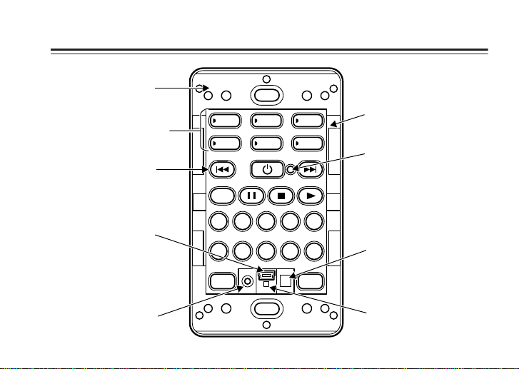
Part Names and Function
Chassis
Source Keys
Membrane
Keypad
SKIP
Key Cap bracket
Set Key
USB socket
IR Receiver
1 2 3 4 5
6 7 8 9 0
-
VOL VOL
Learning
IR sensor
+
System LED &
Volume indicator
5
Page 6
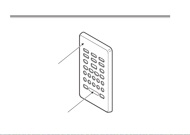
Part Names and Function
Cover Plate
Infra-Red Window
6
—Continued
Page 7

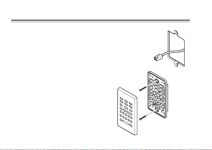
Part Names and Function
Key Cap Membrane
USB Cable
Flush Box screws
RJ45 Connector
—Continued
CD-ROM
CD
DMS
MCD
iPod
XM
SKY
WEB
PC
CD2
TU2
CAM1
Tuner
AUX
VID
iPod2
Sirius
DVR
Request
TAP E
TV
PROJ
CAM2
Cable
DVD
SAT
MP3
TIVO
FOX
Imerge
Lights
Room2
SCRN
CAM3
7
Page 8
Installation
The KEY-5.7 chassis mounts directly to the wall
surface. The following steps outline the installation
procedure:
• Cut out the required mounting hole in the wall
above the flush-box.
•Terminate a RJ45 plug to the CAT5E cable see
wiring instructions on page 8.
• Connect the RJ45 plug to the KEY-5.7.
• Secure the keypad in position using the supplied
flush-box screws.
• Program the keypad either manually or via a
USB connected PC running Integra Keypad
manager.
Note: the KEY-5.7 must have +12V connected
before it can be programmed.
• Select the required Source Key Cap’s, and
secure in position using the Key Cap Bracket.
• Push the keypad cover plate into position.
8
Page 9

12345678
System Wiring
CAT5E cable terminated with a RJ45 plug is used to connect to the KEY-5.7.
Use the standard 568-B color code for the CAT5E termination:
Pin # Wire Color Keypad function
1 White/Orange +12V DC supply
2Orange 0V supply
3 White/Green IR output
4 Blue nc
5 White/Blue Data input
6 Green 0V supply
7 White/Brown nc
8 Brown nc
When cabling use CAT5E home runs with a maximum length of 200m.
“Daisy chaining” or parallel connection of up to four keypads per CAT5E cable may be used.
9
Page 10

System Wiring —
Continued
Connecting to an Integra Multi-Zone amplifier MZA-4.7
KEY-5.7 keypads are wired to the
MZA-4.7 Interface port.
Integra controllers - keypad’s may be parallel connected.
IR emitters plug into the IR outputs
and are fixed to the source equipment’s IR windows.
Note: Ports IR1 and IR2 are Inter-
face port specific, while ports
IR1+IR2 relay the signals from
both interface ports.
10
Page 11

1 2 3 4 5
6 7 8 9 0
SKIP
-
VOL VOL
+
Manual Programming
The SET Key is used along with the Source Keys to put the keypad into various programming
modes.
The SET key is pushed first - System LED flashes Green followed by the relevant source or
function key.
The functions are:
S1 Learn Mode
S2 Integra Mode
S3 Macro Mode
S5 Long Press Mode
S6 Reset
Standby IR Receiver Toggle
VOL+ Volume Level Indicator Dimming
–VOL Source Select Indicator Dimming
Skip +
Skip –
Backlight Dimming
Backlighting Toggle
11
Page 12

Manual Programming
—Continued
LEARN MODE = SET + S1
Before entering Learn
mode the required
Source Bank should
be selected by pushing it’s Source Key.
To enter LEARN mode push SET followed by
the S1 key, the System LED flashes amber.
Push the Key you wish to donate an IR to, system LED stops flashing (Ready to receive an
IR code).
Place the donating remote approximately
80mm away from the Learning IR sensor and
push the remote control key, holding down
until the system LED turns green (Code
learnt).
It is possible to over power the IR sensor in
which case the system LED flashes RED
(Learn failure). Simply push the keypads key
12
again and repeat the IR donating procedure
moving the remote further away from the
Learning IR sensor.
If the remote control is a Pulse code type then
the System LED will also flash RED. Wait for
the System LED to go Amber then from the
same position push the remote controls key a
second time, the keypad assumes no carrier
and the pulse code is Learnt.
Once all the codes in the selected bank have
been learned, push the SET key to exit.
Integra MODE = SET + S2
Push SET followed
by the S2 Key to enter
Integra mode. The
System LED flashes
teal.
Page 13

Manual Programming
Enter a 3 digit numeric representation of the
keypad’s setup:
First two digits are the Zone: 00 - 31.
The third digit is:
0 = Amplifier Zone,
1 = Preamplifier Zone
2 = Amp & Preamplifier toggle.
Typical codes are: 010 = Zone 1 amplifier, 041
= Zone 4 Preamplifier.
Once a correct 3-digit sequence is entered
Integra mode automatically exits. Alternatively, with a connected MZA-4.7 turn ON
and OFF the zone twice. The keypad detects
the amplifier and programs itself to address
the zone and device. Integra mode automatically exits.
—Continued
MACRO MODE
(Sequential) = SET + S3
(Alternating) = SET + S3 + SET
Push SET followed
by the S3 key to enter
Macro Sequential
mode.
The system LED
flashes amber/green. Pressing the SET key a
second time selects the Macro Alternating
mode - system LED flashes red/green.
Donating IR codes is the same process as
Learn.
After learning two commands in Macro Alternating mode the keypad automatically exits.
After learning a string of sequential IR codes
exit by pushing the S1 key.
13
Page 14

Manual Programming
—Continued
LONG PRESS MODE = SET + S5
This mode adds a second function to a key
already programmed.
The second function
will be sent by the
Keypad if the Key is pushed down longer than
0.7 seconds.
Push SET followed by the S5 key to enter
Long press mode, the system LED glows
amber.
Push the key that requires the Long-press
function - donate the IR code - the system
LED glows green.
Exit by pushing the SET key.
14
RESET = SET + S6 + S6
To reset the keypad,
deleting all Learnt IR
commands push SET
followed by two S6
pushes. The System
LED will go from RED to GREEN at the
completion of the memory wipe.
IR RECIEVER TOGGLE = SET +
Standby
The IR receiver is
normally disabled. To
enable the receiver
press SET followed
by the Standby Key,
the System LED will flash Green/white. Pushing Standby a second time toggles the IR
receiver OFF, system LED will flash RED/
white. Exit by pushing the SET key.
Page 15

Manual Programming
—Continued
SOURCE INDICATOR DIMMING =
SET + –VOL
The source indicator brightness may be
adjusted: Push SET, then push – VOL to cycle
through 25%, 50% and 100% levels. Exit by
pushing the SET key.
VOLUME LEVEL INDICATOR
DIMMING = SET + VOL+
The Volume Level indicator brightness may
be adjusted:
Push SET, then push the VOL+ to cycle
through OFF, 50% and100% levels. Exit by
pushing the SET key.
BACKLIGHT DIMMING =
SET +
The Backlight brightness may be adjusted:
Push SET, then push the key to toggle
through OFF, 25%, 50% and 100% levels.
Exit by pushing the SET key.
BACKLIGHTING TOGGLE =
SET +
The backlighting may be set to illuminate
continuously or for 30 seconds after a key
press.
Push SET, then push the key to toggle
settings.The System LED will go green indicating continuous backlighting, push the
key a second time and system LED goes Yellow indicating the backlight will be on for 30
seconds after a keypress. Exit by pushing the
SET key.
15
Page 16

Troubleshooting
One source does not operate, or
operates intermittently.
– Check the IR emitter is OK, ie. Swap it to
other source equipment that is being controlled.
– Ensure the IR emitter is directly over the
source equipment’s IR window.
– Check to see if the source gear can be
controlled via the IR receiver, If it can
then try learning the codes again, ensuring the correct bank has been selected.
– Some brands of equipment expect differ-
ent code on alternate key pushes, reprogram the keypad with the alternate codes
using the alternate Macro feature.
16
Controls an MZA-4.7 but not the
source equipment.
– Ensure the IR emitter is connected to the
correct IR output port on the MZA-4.7.
No control at all.
– The KEY-5.7 forms just one part of an IR
system. There are potential issues with
connections, wiring, power supply, IR
receiver and emitter placement, plus
other optical and EM interference and
ground loop possibilities.
– It is best to strip the IR system back to just
one controller and debug from there.
–With no IR activity the IR terminal
should read 0V - if not then check all wiring and connections, ensure the keypad
programming is correct, and the
Page 17

Troubleshooting
keypad is functioning correctly ie.
Source key flashes when a key with
learnt function is pressed. Try replacing
the IR emitters - these are readily damaged if connected across the Controller
Interfaces power supply.
—Continued
Keypad does not track the MZA-
4.7.
– Ensure the data termination has integrity,
and is not shorted to other conductors in
the CAT5E. Ensure the keypad is cor-
rectly zoned.
17
Page 18

Specifications
IR Learning
Compatible with virtually all brands of remote
controls using carrier or modulation frequencies between 20KHz and 500KHz.
Also capable of learning non-modulated pulse
codes with a minimum pulse width of 10
Memory
12Kbytes - IR codes are stored in Flash memory.
IR receiver
Passthrough of modulated infrared whose carrier frequency is within the range of 32KHZ -
44.1KHz.
Range: typically 8m - Dependant on ambient
light level, angle of incidence and the remote
controls battery condition.
µ
s.
18
Wiring
Up to 200 m of CAT5E home run cable.
Voltage Current
12 V DC ±3 V
Typically 50 mA, Max=120 mA
Dimensions
Cover Plate: Width = 75mm, Height =
120mm,
Depth = 4.6mm
Depth behind plate = 20mm
Compliance
ICES-003, FCC.
Page 19

Template 1
19
Page 20

20
Page 21

Template 2
21
Page 22

22
Page 23

Memo
23
Page 24

Integra Division of
ONKYO U.S.A. CORPORATION
18 park Way, Upper Saddle River, N.J. 07458, U.S.A.
Tel: 201-785-2600 Fax: 201-785-2650
http://www.integrahometheater.com
Integra Division of
ONKYO CORPORATION
Sales & Product Planning Div.: 2-1, Nisshin-cho
Neyagawa-shi, OSAKA 572-8540, JAPAN
Tel: 072-831-8023 Fax: 072-831-8124
SN 29344404
(C) Copyright 2006
ONKYO CORPORATION Japan. All rights reserved.
E
D0610-1
* 2 9 3 4 4 4 0 4 *
n
 Loading...