

Page 1
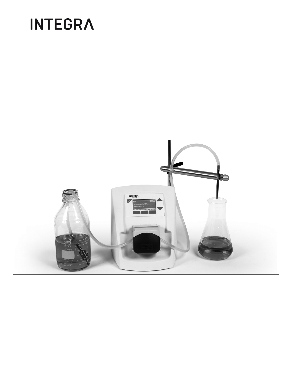
DOSE IT Operating instructions
171250_V08
Page 2

Declaration of conformity
INTEGRA Biosciences AG –
7205 Zizers, Switzerland
declares on its own responsibility that the device
complies with:
Zizers, November 4, 2016
Description Model
DOSE IT P910 171 000
EU Directives (DoW: Date of Withdrawal) Before DoW DoW After DoW
Low Voltage Equipment 2006/95/EC 20.04.2016 2014/35/EU
Electromagnetic Compatibility 2004/108/EC 20.04.2016 2014/30/EU
Restriction of Hazardous Substances 2011/65/EU
Waste Electrical and Electronic Equipment 2012/19/EU
EU Regulations
Registration, Evaluation, Authorisation and Restriction of Chemicals (REACH)
1907/2006
Ecodesign - Power supplies 278/2009
Standards for EU
Safety requirements for electrical equipment for measurement,
control and laboratory use - General requirements.
EN 61010-1: 2010
Electrical equipment for measurement, control and laboratory use EMC requirements.
EN 61326-1: 2013
Standards for Canada and USA
Safety requirements for electrical equipment for measurement,
control and laboratory use - General requirements.
CAN/CSA-C22.2
No. 61010-1
Safety requirements for electrical equipment for measurement,
control and laboratory use - General requirements.
UL 61010-1
Operation is subject to the following two conditions:
(1) this device may not cause harmful interference, and
(2) this device must accept any interference received, including
interference that may cause undesired operation.
Part 15 of the
FCC Rules
Class A
Elmar Morscher
CEO
Thomas Neher
Quality Manager
Page 3

DOSE IT – Operating instructions V08
www.integra-biosciences.com 3
Table of contents
Chapter 1 Introduction
1.1 Intended use ..................................................................................5
1.2 Symbols used.................................................................................5
1.3 Safety notes ...................................................................................6
Chapter 2 Description of the device
2.1 Scope of delivery............................................................................7
2.2 Overview of the DOSE IT...............................................................7
Chapter 3 Installation
3.1 Power supply connection ...............................................................9
3.2 Retort rod and filling arm (optional)................................................9
Chapter 4 Operation
4.1 Selection and loading of the tubing ..............................................10
4.2 Parameter settings.......................................................................13
4.3 Adjusting the dispensing program................................................15
4.4 Calibrating the pump ....................................................................18
4.5 Performing the dispensing process..............................................19
4.6 Working in Pump mode................................................................19
4.7 Using the double pumphead configuration (optional)...................20
4.8 Process documentation (optional)................................................21
4.9 Using the foot and benchtop switch .............................................22
4.10 Remote control by a PC .............................................................22
Chapter 5 Maintenance
5.1 Cleaning and servicing.................................................................23
5.2 Decontamination ..........................................................................23
5.3 Leak Test .....................................................................................23
5.4 Disposal .......................................................................................24
Chapter 6 Technical data
6.1 Environmental conditions.............................................................25
6.2 Specifications ...............................................................................25
6.3 Current consumption depending on input voltage........................25
6.4 Chemical compatibility .................................................................26
Page 4

DOSE IT – Operating instructions V08
4 INTEGRA Biosciences AG
Chapter 7 Accessories and consumables
7.1 Consumables ...............................................................................27
7.2 Spare part ....................................................................................28
7.3 Accessories..................................................................................29
Imprint .................................................................................................30
Page 5
DOSE IT – Operating instructions V08 Introduction
www.integra-biosciences.com 5
1 Introduction
1.1 Intended use
This is a general-purpose laboratory instrument. Any use of this instrument in a medical
or IVD setting is the sole responsibility of the user.
The programmable peristaltic pump DOSE IT is designed for pumping and dispensing
liquids in a volume range of 0.1 ml to 9999 ml using silicone tubings.
If the DOSE IT is used in a manner not specified by INTEGRA, the protection provided by
the DOSE IT may be impaired.
1.2 Symbols used
This operating instruction manual makes specific reference to residual dangers using the
symbols shown below.
1.2.1 Hazard warnings in these operating instructions
W
ARNING
This safety symbol advises of hazards that could result in injury or death.
It also indicates hazards for machinery, materials, and the environment.
It is essential that you follow the relevant precautions.
C
AUTION
This symbol cautions about potential material damage or data loss in a
microprocessor controller. Follow the instructions.
N
OTE
This symbol identifies important notes regarding the correct operation of the
device and labor-saving features.
1.2.2 Hazard warnings on the device
R
OTATING COG WHEELS
Risk to squash your fingers.
Page 6

DOSE IT – Operating instructions V08 Introduction
6 INTEGRA Biosciences AG
1.3 Safety notes
The DOSE IT conforms to the state of technology and the recognized safety rules, and is
operationally safe. Operate the DOSE IT when in perfect conditions only and observing
this user manual.
Residual dangers can emanate from the device if it is used or operated incorrectly by
untrained personnel. All persons entrusted with operation of the DOSE IT must have read
and understood this user manual and, in particular, the safety notes, or must have been
instructed by their superior such that they are able to operate the device without danger.
Please observe the danger references on the device.
Do not carry out any conversion work or alterations on the device.
Irrespective of the safety instructions set out here, applicable provisions and regulations
must be observed in addition; for example, GLP, GMP, FDA, of the employer's liability
insurance associations, of the health authorities and of the trading standards authorities.
Please visit our website www.integra-biosciences.com
on a regular basis for up to date
information regarding REACH classified chemicals contained in our products.
Page 7
DOSE IT – Operating instructions V08 Description of the device
www.integra-biosciences.com 7
2 Description of the device
2.1 Scope of delivery
• DOSE IT P910 peristaltic pump
• Silicone tubing, autoclavable, 4 mm inner diameter (ID)
• 2x Aspiration/dispensing tubes 10 cm, stainless steel, 4 mm ID,
one end dented
• Aspiration tube 35 cm, stainless steel, 4 mm ID, one end dented
• Tube collar
• AC adapter
• Operating Instructions
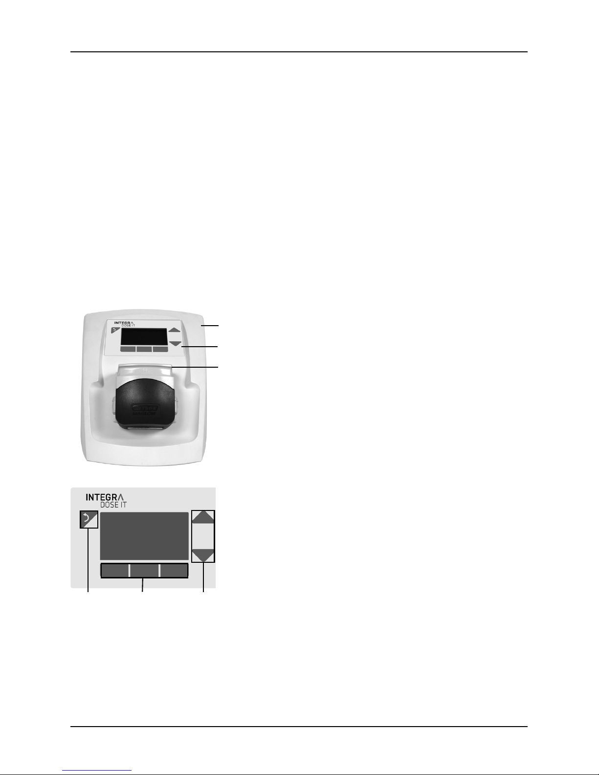
2.2 Overview of the DOSE IT
Front view
1Housing
2 Operating panel with display and keypad
3 Pumphead
Operating panel
4 Back-key
5 Function keys
6 Arrow keys
4
5
6
Page 8

DOSE IT – Operating instructions V08 Description of the device
8 INTEGRA Biosciences AG
Rear view
7 Screw threads for fixation of the retort rod
8 Handhold
9 Connections and mains switch (see below)
78 9
Connections and mains switch
10 RS-232 interface for connection with serial printer
11 RS-232 interface for service connection
12 AUX connection for controlling a second DOSE IT
13 Mains switch
14 Connection for foot switch, benchtop switch,
MEDIAJET or external relay contact (potential free,
normally open, 3.5 mm jack plug) for remote control
15 Mains connection socket
10
11
12
13
14
15
Page 9
DOSE IT – Operating instructions V08 Installation
www.integra-biosciences.com 9
3 Installation
The DOSE IT is a ready-to-use peristaltic pump that requires only a minimal installation
procedure. It shall be installed on a planar surface, in a dry and dust-free environment.
N
OTE
Before proceeding with the installation compare the contents of the package
with the list “2.1
Scope of delivery” on page 7. Should something be missing
or should you find a faulty component, please contact your local INTEGRA
Biosciences representative.
3.1 Power supply connection
Connect the AC adapter cable to the DOSE IT mains connection socket and plug it to the
electricity mains.
W
ARNING
The supply voltage must meet the requirements of the AC adapter:
100 - 240 VAC, 50 - 60 Hz.
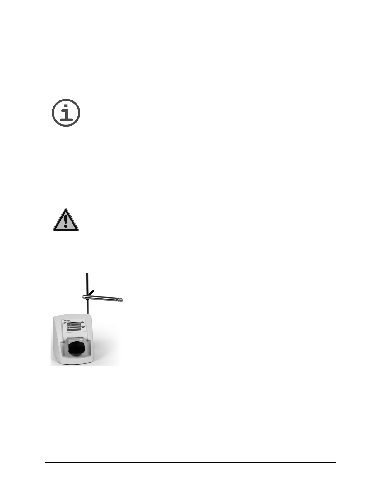
3.2 Retort rod and filling arm (optional)
Fix the retort rod with the two screws on the rear side, using
a Phillips screwdriver (PH2), see "
Screw threads for fixation
of the retort rod" on page 8.
Mount the filling arm onto the rod and tighten it with the side
lever in order to prevent it from moving during dispensing.
Page 10
DOSE IT – Operating instructions V08 Operation
10 INTEGRA Biosciences AG
4 Operation
The DOSE IT operates in different modes: DISPENSE mode for distribution of a defined
volume into containers and PUMP mode for continuous pumping of liquids. In addition,
customized applications can be defined (software version 2.0 and higher).
4.1 Selection and loading of the tubing
4.1.1 Tubing selection
The pumphead of the DOSE IT is compatible with differently sized tubing allowing the user
to dispense a wide range of dose volumes. The main criteria for the choice of tubing are
the speed and precision requirements of a specific application. The larger the inner
diameter (ID) of the tubing, the faster but less precise is the dispensing.
As a reference for selecting the appropriate inner diameter of the tubing, typical volume
and speed values for different tubing sizes are listed in Table 1.
N
OTE
The indicated volume values relate to the specified reproducibility and not to
the actual limits of the system. The values have been determined
experimentally and may vary slightly depending on the experimental set up.
Compatibility with the pumphead and specified reproducibility can be guaranteed for
original INTEGRA Biosciences’ tubing only.
N
OTE
8 mm ID tubing is only recommended for the “PUMP” program mode (for
accuracy reasons, drips between the aliquots and draw backs in the tubing
may be a problem).
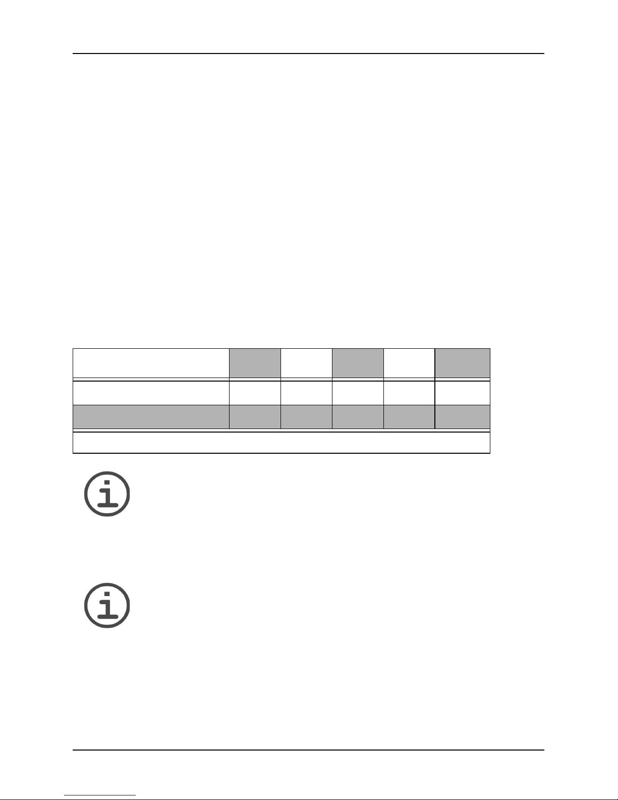
Table 1: Typical volume and speed values
Tubing inner diameter (ID) 1 mm 2 mm 3 mm 4 mm 6 mm
Volume (ml) at CV* < 1 % > 0.5 > 1 > 3 > 7 > 15
Speed range (ml / min) 0.6 – 52 2.1 – 203 4.8 – 475 8.4 – 837 16 – 1634
* Coefficient of variation.
Page 11
DOSE IT – Operating instructions V08 Operation
www.integra-biosciences.com 11
4.1.2 Loading of the tubing in the pumphead
W
ARNING
Always switch off the DOSE IT when loading the tubing and when
manipulating the open pumphead.
C
AUTION
Do not adjust the tubing clamps according to the scale on the pumphead
sides because the tubing will be unnecessarily squeezed and might be
damaged. Also the pumping precision will be diminished. Use instead the
adjustments described in Table 2.
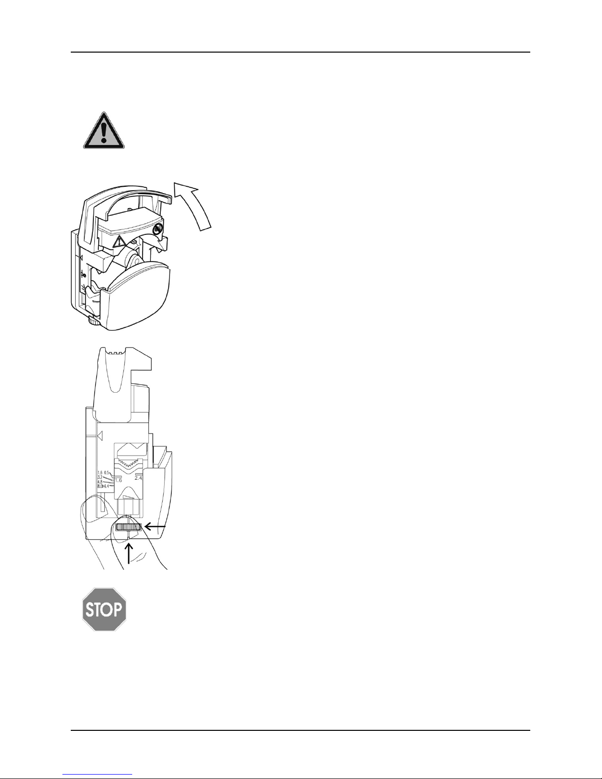
1 Open the pumphead
2 Adjust the tubing clamps
The jagged, V-shaped tubing clamps on both sides of
the pumphead need to be adjusted and guarantee that
the tubing does not slip when the rotor turns. The tubing
clamps are set by adjusting the finger screws in such a
way as to match the diameter of the tubing.
Page 12

DOSE IT – Operating instructions V08 Operation
12 INTEGRA Biosciences AG
Table 2: Adjustments of the clamps for differently sized tubing
4.1.3 Connecting the dispensing and aspiration tubes
Clamp Tubing ID 1.6-marking of clamps
1 mm between 3.2 and 4.8 scale values
2 mm matches the 4.8 value on the scale
3 mm matches the 6.4 value on the scale
4 – 8 mm Completely open the clamps as shown beside.
Turn the finger screws right till the stop position.
3 Insert the tubing
Place the tubing over the rollers and center it so that it
comes out of the pump head over the clamps on both
sides. Close the pumphead and make sure that the tubing exits the pumphead unhindered and bending downwards. The tubing must not be bent upwards or towards
the front or back.
The aspiration/dispensing tubes delivered with the
DOSE IT facilitate the dosing process and are fitted on
the end of the tubing. The aspiration tube is dented on
one end in order to guarantee a free flowing of the liquid
entering the tubing. Make sure not to insert the dented
end of the aspiration tube into the silicone tubing.
The tube collar can either be screwed on the aspiration
tube to weigh it down or to the dispensing tube as a
spacer for use with a clamp.
Dented end
Tube collar
Aspiration/
dispensing
tube
Silicone tubing
Page 13

DOSE IT – Operating instructions V08 Operation
www.integra-biosciences.com 13
4.2 Parameter settings
4.2.1 System parameters
4.2.2 Program parameters
Some parameters described are not displayed in every program mode.
System-Parameter Description
Language Set the desired language.
Time/Date Set time and date.
Display contrast Change the contrast of the display.
Access code Provides user access restrictions to parameters.
Info General information on the unit:
• Version of the software
• Version of the electronics
• Serial number.
Parameter Description Range Default
Name Allows to name the program with up to 16
alphanumeric symbols. Press the arrow keys
simultaneously to delete the program name.
--
Type Defines the program mode: “P
UMP” for continu-
ous pumping of a liquid, “D
ISPENSE” for the
dosing of liquids, or “C
USTOMIZE” to create a
customized application.
Dispense
Pump
Customize
Dispense
Tubing-ID
(mm)
Defines the Inner Diameter (ID) of the tubing. 1.0 – 8.0 mm 4.0 m m
Flow rate
(ml/min)
Allows to set the pump speed. The flow rate
depends on the tubing inner diameter.
Time
(h min s)
Defines the duration of the pumping. Entering
0 h 0 min 0 s puts the unit in continuous operation, which is represented by the infinite symbol
(.
1'' – 9 h 59' 59''1h
Volume Defines the volume of a dose in the dispensing
mode.
0.01 – 9999 ml 10 ml
Repetitions Defines the number of doses in the dispensing
mode. Entering 0 results in an unlimited number of doses, which is represented by the
infinite symbol (.
1 – 999
20
Page 14

DOSE IT – Operating instructions V08 Operation
14 INTEGRA Biosciences AG
Customize mode
The ‘Customize’ mode allows to program a customized application consisting of up to 20
single steps:
Pause Defines the duration of the interval between
doses in the dispensing mode. If switching to
manual, the dispensing of a dose has to be
activated manually.
0.1– 99.9 s,
manual
1.0 s
Direction Defines the rotational direction of the rotor and
hence the flow direction. / C W m e a n s c l o c k wise, / CCW means counter-clockwise.
/ C W
/ C C W
/ C W
Dispense
direction
Defines the rotational direction for the step type
“D
ISPENSE”. For the step type “ASPIRATION” the
rotor rotates oppositely.
/ C W
/ C C W
/ C W
No. of
heads
Defines the number of pump heads. 1, 2 1
Step 1–20 Defines single steps of a customized applica-
tion.
1–20 -
Step Description Parameter
Dispense Defines the dosing of liquids analog to the program mode
“Dispense”. The rotational direction is defined by the
parameter “Dispense direction’.
Volume
Repetitions
Flow rate
Pause
Dispense
Ramp
Defines dispensing with accelerating or decelerating
speed, needed e.g. for density gradients. Just define the
start and end flow to ramp the dispensing speed up or
down. If the start flow is identical to the speed of the previous step, and the pause of the previous step is set to manual, the liquid can be dispensed without pause.
Volume
Repetitions
Pause
Start flow
End flow
Aspirate Defines the aspiration of liquids analog to the program
mode “Dispense” with opposite rotational direction.
Volume
Repetitions
Flow rate
Pause
Aspirate
Ramp
Defines the aspiration of liquids with accelerating or decelerating speed. Just define the start and end flow to ramp
the aspirating speed up or down. If the speed of the following step is identical to the end flow, and the pause is set to
manual, the DOSE IT continues without pause.
Volume
Repetitions
Pause
Start flow
End flow
Parameter Description Range Default
Page 15

DOSE IT – Operating instructions V08 Operation
www.integra-biosciences.com 15
4.3 Adjusting the dispensing program
4.3.1 Choosing the language
N
OTE
Because it is easiest to operate the DOSE IT by following the instructions on
the screen, please select the language you are most familiar with.
Pump Defines continuous pumping of a liquid. Direction
Flow rate
Time
Wait Defines the duration of the interval between two steps.
Manual mode means that the next step has to be activated
manually.
1'' – 9 h 59' 59''
manual
Cycles Defines the number of cycles of a sequence. A cycle
always initiates a return back to a defined step, e.g. step 1.
You can define several cycles within your customized
sequence.
Number of
cycles
1 –999,
Goto step ¥
- No operation, used as default setup of step. -
Step Description Parameter
1 Switch on the DOSE IT by pressing the mains switch at
the back.
The A
PPLICATIONS window appears. The first four
programs in the application list are already pre-defined
with default values.
2 Press SYSTEM to access the SYSTEM window and set the
language of your choice by accessing the LANGUAGE
menu.
In the S
YSTEM window you can also set the display
contrast, the date and the time, and an access code, if
required.
Page 16

DOSE IT – Operating instructions V08 Operation
16 INTEGRA Biosciences AG
4.3.2 Access code
The DOSE IT system and parameter settings can be protected by a code, if activated
(Access code required ON). Before any parameter changes can be performed, an access
code must be entered. A standard user can only run defined programs.
Select the A
CCESS CODE window and enter the default access code “3473” by typing the
appropriate key until the correct number appears on the screen. Press the back-key.
4.3.3 Setting the dispensing parameters
N
OTE
The DOSE IT has a memory capacity for storing 20 programs, all of which
can be configured according to your specific applications.
1 Select the line “Access code required” and press
C
HANGE. Use the arrow keys to select “Access code
required: ON” and press S
AVE.
2 For changing the Access code select this line and press
S
AVE.
3 Change the default access code to your personal code,
if required. Enter the numbers by the arrow keys and
select the digit with the function keys (, ). Keep this
code in a save place. Press S
AVE.
1 Press the back-key to exit the SYSTEM window and to
return to the A
PPLICATION window. Press PARAMETER to
configure the program that is backlit.
2 Use the arrow keys to select the listed parameters and
press C
HANGE to set different values.
All parameters and their values are described in “4.2.2
Program parameters” on page 13.
Page 17

DOSE IT – Operating instructions V08 Operation
www.integra-biosciences.com 17
4.3.4 Defining a customized program
The following example of a customized program can be used to fill 10 density gradient
tubes. The careful and continuous dispensing without pauses prevents stirring up of
layers.
Parameter Value Description of settings
Name Density
gradient
Allows to name your customized program.
Tubing-ID 3.0 mm Define the inner diameter of the tubing inserted.
Dispense
Direction
/ C W Define the rotational direction of the rotor, e. g. clock-
wise.
No. of heads 1 Define the number of pump heads installed.
Step 1: Dispense Volume: 2.5 ml
Repetitions: 1
Pause: manual (here without pause)
Flow rate: 3.8 ml/min (i.e. speed: 4.0 rpm).
Step 2: Dispense
Ramp
Volume: 12.5 ml
Repetitions: 1
Pause: manual (here without pause)
Start flow: 3.8 ml/min (i.e. speed: 4.0 rpm)
End flow: 22.8 ml/min (i.e. speed: 24.0 rpm).
Step 3: Wait Manual, i.e. the next cycle starting with step 1 has to be
activated manually by pressing N
EXT STEP.
Step 4: Cycles Number of cycles: 10
Goto step: 1.
The figure depicts the
customized program
described above.
Page 18

DOSE IT – Operating instructions V08 Operation
18 INTEGRA Biosciences AG
4.4 Calibrating the pump
NOTE
The calibration procedure tunes the pump to deliver a precise output. The
output of the pump is determined by the tubing's inner diameter; therefore a
calibration is necessary for tubing with different inner diameter. Also calibrate
the pump after changing the fluid to be pumped. It is recommended to
calibrate the pump at regular intervals to maintain its precision.
I
MPORTANT NOTE
A calibration value is stored for each of the 20 programs that can be saved.
Therefore a calibration for each of the 20 programs is necessary, even when
the tubing inner diameter remains the same. Within each program, only the
last calibration value is saved, hence calibrate whenever there is a change in
the viscosity of the pumped liquid, of the flow rate or of the tubing inner
diameter.
Each step within a customized program has to be calibrated separately.
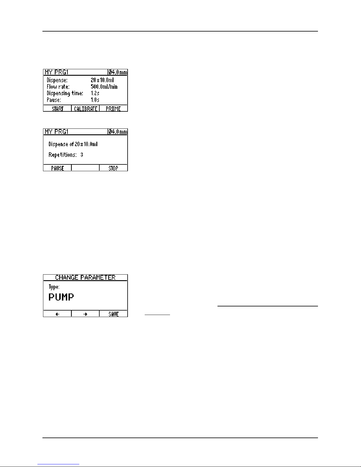
1 Select a program and press START to access the
program window. Put the tubing end with the aspiration
tube in the liquid that has to be dispensed and press
P
RIME to fill the tubing with liquid without bubbles.
2 Press the CALIBRATE button to enter the calibration
dialogue window and DOSING to obtain a calibration
sample. To reduce the measurement error it is possible
to obtain up to ten such dosing samples (by repeatedly
pressing the D
OSING button).
3 After one or more calibration samples have been
dispensed and measured, press the C
ONTINUE button
and enter the measured volume (CHANGE button). To
end the calibration procedure press CONTINUE.
Page 19
DOSE IT – Operating instructions V08 Operation
www.integra-biosciences.com 19
4.5 Performing the dispensing process
4.6 Working in P
UMP mode
1 In the APPLICATION window select a program and press
S
TART to access the program window. Press PRIME to fill
the tubing with liquid until no more bubbles are in the
tube and calibrate if necessary.
To begin dispensing, press S
TART.
2 While dispensing, there are two possibilities to interrupt
the process:
• P
AUSE – the process is interrupted after completing
the dispensing of the current dose.
• S
TOP – the process is interrupted immediately.
After interruption, the process can either be continued, aborted or parameters can be
changed (the latter is not possible in the customize mode). If parameters have been
changed, the user is asked to either save or discard the changes before exiting the
program.
The completion of the program is announced by a beep and a message appears on the
screen.
To continuously pump a liquid instead of dispensing it,
change the T
YPE-parameter from DISPENSE to PUMP. To
set the other parameters follow the instructions described above and in “4.2.2 Program parameters” on
page 13.
The calibration procedure in P
UMP mode works as described above. Note that the
calibration volume is indicated in the calibration window and that it varies depending on
the tubing size and on the selected flow rate.
To use a pumping program, follow the instructions on the screen. Note that you can
change the flow rate without interrupting the pumping by using the arrow keys (not
possible within customized mode).
Page 20

DOSE IT – Operating instructions V08 Operation
20 INTEGRA Biosciences AG
4.7 Using the double pumphead configuration (optional)
The DOSE IT can be used with a double pumphead and the corresponding 8 mm ID tubing
set (171 088) when it is necessary to quickly dispense large volumes. The double
pumphead configuration also reduces flow pulsation.
W
ARNING
Always switch off the DOSE IT when assembling the double pumphead
configuration.
Be aware of the sharp edges of the pumpheads when assembling them and when opening
and closing the first pumphead for tubing insertion.
When placing the tubing set (171 088) into the double pumphead assembly, gently stretch
the tubing so that inside the pumphead the tubing is taut (avoid loading the tubing in a
loose, slackened way).
W
ARNING
Visually inspect the tubing set Y-pieces for the absence of cracks in the glass.
Cracked Y-pieces may burst during operation and shall not be used.
In the affected programs, change the parameter “No. of heads” before using the double
pumphead configuration.
1 Open the pumphead to gain access to the two fixation
screws and unscrew the pumphead from the housing
using an Allen key # 3.
2 Fix the extension pumphead (171 090) to the housing
using the screws obtained after removing the original
pumphead.
Fixation screws
3 Assemble the two pumpheads by locking the original
pumphead onto the extension pumphead. When turning
the original pumphead in place, ensure that the lock
mechanism engages with an audible click.
Important: The rollers of the two pumpheads must be
out of phase in order to avoid excessive strain on the
motor (torque limits) and to obtain a reduction in flow
pulsation.
Page 21

DOSE IT – Operating instructions V08 Operation
www.integra-biosciences.com 21
4.8 Process documentation (optional)
To document the dispensing and pumping performed with a DOSE IT, relevant data can
be recorded either on paper or in an electronic text file. The following data – exemplified
by a dispensing program – are recorded:
• At the start of the process
========================================
DOSE-IT (SN:00000000)
***Start dispense
Date/time: 02.11.2006/18:01
***Program settings
Name: MY PRG1
Tubing-ID: 4.0mm
Volume: 10.0ml
Repetitions: 20
Pause: 1.0s
Flow rate: 500.0ml/min
Direction: CW
No. of heads: 1
========================================
• After calibration
========================================
DOSE-IT (SN:00000000)
***Calibration done
Date/time: 02.11.2006/18:05
Tubing-ID: 4.0mm
========================================
• At the end of the process
========================================
DOSE-IT (SN:00000000)
***End dispense
Date/time: 02.11.2006/18:02
Repetitions: 20
***Program settings
Name: MY PRG1
Tubing-ID: 4.0mm
Volume: 12.0ml
Pause: 1.0s
Flow rate: 500.0ml/min
Direction: CW
No. of heads: 1
========================================
Note: This parameter
has been changed
during the process.
Page 22

DOSE IT – Operating instructions V08 Operation
22 INTEGRA Biosciences AG
Printing on paper occurs automatically when a label printer is connected to the RS - 232
(2) port of the DOSE IT. INTEGRA Biosciences recommends the EPSON TM-U220 matrix
printer and your local INTEGRA dealer can assist you to connect this printer.
To generate an electronic text file, connect a PC to the RS - 232 (2) port of the DOSE IT
via a crossed female-female RS - 232 cable and record the process data using the
HyperTerminal software installed on your PC.
RS - 232 (2) interface settings:
Transmission speed:......... 9600 bps
Databits:............................ 8 bits
Parity:................................ No
Stopbits: ............................ 1
Handshake:....................... Xon / Xoff
4.9 Using the foot and benchtop switch
The optional foot switch or benchtop switch can be used for hands-free operation. There
are no specific setting needed, just connect one of the switches.
Depending on program mode and step, the switch can be used instead of the S
TART,
PAUSE or STOP key. However, the keys will still work, even if a switch is connected.
In D
ISPENSE mode, set the PAUSE parameter to manual. The first pedal/button pulse starts
the set number of doses, the next pulse will pause the process, and so on until the process
is completed.
In P
UMP mode, the pump starts with the first pedal/button pulse (=START). With the next
pulse it stops (=STOP) and so on.
4.10 Remote control by a PC
Remote operation can be performed by simulating the foot switch, e. g. with a PC and an
input/output interface box as described above for the foot switch.
Page 23

DOSE IT – Operating instructions V08 Maintenance
www.integra-biosciences.com 23
5 Maintenance
5.1 Cleaning and servicing
WARNING
Always switch off the DOSE IT and disconnect it from the mains when
carrying out maintenance work.
If the DOSE IT gets soiled, it can be cleaned with a cloth moistened with soapy water or
with a 70 % solution of Ethanol.
Regular servicing of the DOSE IT by a qualified partner of INTEGRA Biosciences is
recommended.
5.2 Decontamination
The aspiration/dispensing tubes, tube collars and silicone tubing contacting the liquid can
be autoclaved at 121°C, 1 bar overpressure for at least 20 minutes. Silicone may become
brittle after extensive autoclaving. Replace the tubings if they are damaged.
If the surface of the DOSE IT has been in contact with biohazardous material, it must be
decontaminated in accordance to good laboratory practice. Do not spray directly on the
instrument but use a lint-free cloth, lightly soaked with a disinfectant and wipe dry directly
after decontamination. Never use acetone or other solvents! Follow the instructions
provided by the disinfectant manufacturer.
5.3 Leak Test
It is recommended to perform a leak test about every 3 months or when dosing errors
occur. A leak test will reveal worn or defect tubing or pumphead.
Procedure:
1) Load a silicone tubing in the pumphead.
2) Position the dispensing end of the tubing below the pumphead height into a container.
3) Put the aspiration tube in liquid and press P
RIME to fill the tubing completely without
any bubbles.
4) Lift the aspirating end of the tubing as high as possible above the pumphead. The
system is tight, if the liquid level do not decrease and no liquid flow out of the lower
dispensing end.
The moving parts of the pumphead should be
checked from time to time for freedom of movement.
Occasionally lightly grease the lever (1) and the
rollers (see image) with Teflon lubrication oil.
The rotor shaft runs on sealed bearings which do not
require lubrication.
1
Page 24

DOSE IT – Operating instructions V08 Maintenance
24 INTEGRA Biosciences AG
If the system is leaking, you have to check whether the tubing or the pumphead is worn:
Repeat the leak test with a new tubing (only use original INTEGRA tubings, see “7.1
Consumables” on page 27).
• If system is tight, the tubing was worn and the problem is solved.
• If the system is still leaking, the pumphead is worn (e.g. lever loose, mechanical play)
and need to be replaced, see “7.2 Spare part” on page 28
.
N
OTE
Work around until a new pumphead is available: Put a rubber band (5 to
8 mm wide) around the pumphead to help holding it fully closed during operation. Repeat the leak test to confirm that the work around works.
5.4 Disposal
The DOSE IT is labeled with the “crossed-out bin” symbol to indicate that this
equipment must not be disposed of with unsorted municipal waste. Instead,
it is your responsibility to correctly dispose of your waste equipment by handing it over to an authorized facility for separate collection and recycling. It is
also your responsibility to decontaminate the equipment in case of biological,
chemical, and/or radiological contamination so as to protect from
health hazards the persons involved in the disposal and recycling of equipment.
For more information about where you can drop off your waste equipment for recycling,
please contact your local dealer from whom you originally purchased the product or your
local council.
By doing so, you will help conserve natural resources and you will ensure that your waste
equipment is recycled in a manner that protects human health and the environment.
Thank you!
Page 25

DOSE IT – Operating instructions V08 Technical data
www.integra-biosciences.com 25
6 Technical data
6.1 Environmental conditions
6.2 Specifications
6.3 Current consumption depending on input voltage
Operation
Temperature range 5–35 °C
Humidity range Max. rel. humidity 80 % for temperatures up to 31 °C,
decreasing linearly to 50 % rel. humidity at 40 °C.
Altitude range < 2000 m
Dose volume 0.01 ml – 9999 ml
Flow rate 0.6 ml / min – 5 l / min
Tubing inner diameter 1 – 8 mm
Tubing wall thickness 1.5 mm
Materials Housing: Polyurethane
Base plate, rear panel: stainless steel
Membrane keypad: Polyester
Tubing: Silicone
Pump head body rear: Polypropylene
Pump head body front: IXEF
Pump head tube clamps: Nylon
Pump head roller: Nylatron
Dimensions (H x W x D) 203 x 210 x 191 mm
Weight 3.5 kg
Interfaces 2 x RS-232
Electricity supply Input: 100 – 240 VAC, 50 / 60 Hz
Output: 46.6 – 49.4 VDC, 70 W
Current consumption
Input voltage Standby
Operation with
1 or 2 pump heads
Pause mode
100 VAC 45 mA 260 mA 280 mA
230 VAC 15 mA 120 mA 130 mA
Page 26

DOSE IT – Operating instructions V08 Technical data
26 INTEGRA Biosciences AG
6.4 Chemical compatibility
A particular advantage of peristaltic pumps is that the fluid remains enclosed inside the
tubing. Even chemical aggressive liquids can be transferred without the risk of damaging
parts of the pump as long they are compatible with the silicone tubing. The table below
rates the compatibility of silicone to a few of the chemicals commonly used in laboratories.
INTEGRA Biosciences AG assumes no liability for the information contained in the table.
Compatibility ratings for silicone tubing:
A = good, little to minor effects (0-5 % volume swell).
B = fair, moderate effects, not recommended for continuous use (5-10 % volume swell).
C = critical, not recommended (10 % or greater volume swell).
To determine the compatibility silicone to a chemical not listed in the table, please consult
one of the several tables available on the internet, e. g. Watson Marlow with material
Pumpsil (silicone).
It is the responsibility of the users to ensure the chemical compatibility. Before using a
critical chemical, immerse a short piece of the tubing in a closed container of the chemical
for 48 hours. Check the tubing for sings of swelling, softening, discoloration, embrittlement
or any other attack.
Chemical Rating
Acetic acid CH3COOH B
Acetone C3H6O C
Acetonitrile C2H3N C
Dimethyl sulfoxide DMSO A
Ethanol C2H5OH B
Hydrochloric acid 33 % HCl C
JAVEL NaClO A
Phenol C6H5OH C
Sodium carbonate Na2CO3 A
Sodium hydroxide 50 % NaOH B
Page 27

DOSE IT – Operating instructions V08 Accessories and consumables
www.integra-biosciences.com 27
7 Accessories and consumables
There are a number of accessories and options that adapt the DOSE IT to particular
application requirements and working environments.
7.1 Consumables
7.1.1 Silicone tubing
ID
1
(mm)
1. ID = inner diameter
Part No.
length 2.5 m, autoclavable,
wall thickness 1.5 mm.
1 171 021
2 171 022
3 171 023
4 171 024
6 171 026
8 171 028
2
2. only for pumping applications
length 25 m, (bulk roll), autoclavable,
wall thickness 1.5 mm.
1 171 031
2 171 032
3 171 033
4 171 034
6 171 036
8 171 038
2
Page 28

DOSE IT – Operating instructions V08 Accessories and consumables
28 INTEGRA Biosciences AG
7.1.2 Aspiration/dispensing tubes
7.1.3 Tube collars
7.2 Spare part
ID (mm) Part No.
Aspiration/dispensing tube, length 10 cm,
stainless steel, one end dented.
1 171 051
2 171 052
3 171 053
4 171 054
6 171 056
8 171 058
Aspiration/dispensing tube, length 35 cm,
stainless steel, one end dented.
4 171 064
6 171 066
8 171 068
ID (mm) Part No.
Used as weight for the aspiration tube or
as clamp spacer for the dispensing tube.
See also “4.1.3
Connecting the dispensing
and aspiration tubes” on page 12.
1 – 3 171 071
4 – 6 171 074
Part No.
Pumphead 313D 103 520
Page 29
DOSE IT – Operating instructions V08 Accessories and consumables
www.integra-biosciences.com 29
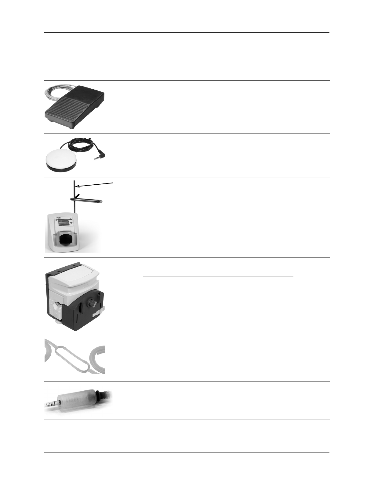
7.3 Accessories
Part No.
Foot switch. 143 200
Benchtop switch. 171 081
Retort rod with filling arm. 171 091
Extension pumphead for double pumphead assembly.
See also “4.7 Using the double pumphead configuration
(optional)” on page 20.
171 090
Silicone tubing set for double pumphead (ID 8 mm), total
length 3 m, autoclavable, incl.
• 2 short silicone tubings (ID 8 mm)
• 2 Y-pieces made of glass
• 2 long silicone tubings (ID 10 mm)
171 088
Pipette-tubing connector, for connecting pipettes to
2-6 mm inner diameter silicone tubing, autoclavable,
5-pack
171 077
Page 30

DOSE IT – Operating instructions V08
30 INTEGRA Biosciences AG
Imprint
© 2018 INTEGRA Biosciences AG
All rights to this documentation are reserved. In particular the rights of reproduction,
processing, translation and the form of presentation lie with INTEGRA Biosciences AG.
Neither the complete documentation nor parts thereof may be reproduced in any way, or
stored and processed using electronic media or distributed in any other way without the
written consent of INTEGRA Biosciences AG.
This operating instruction manual has the part number 171 250, version number V08. It
applies to firmware version 2.02 or higher until a newer revision is released.
Manufacturer
Customer service
Please contact your local INTEGRA Biosciences representative.
To find out name and address of your local representative go to
www.integra-biosciences.com
.
Further information and operating instructions in other languages are available on
www.integra-biosciences.com
or on request (info@integra-biosciences.com).
INTEGRA Biosciences AG
CH-7205 Zizers, Switzerland
T +41 81 286 95 30
F +41 81 286 95 33
INTEGRA Biosciences Corp.
Hudson, NH 03051, USA
T +1 603 578 5800
F +1 603 577 5529
info@integra-biosciences.com
www.integra-biosciences.com
 Loading...