

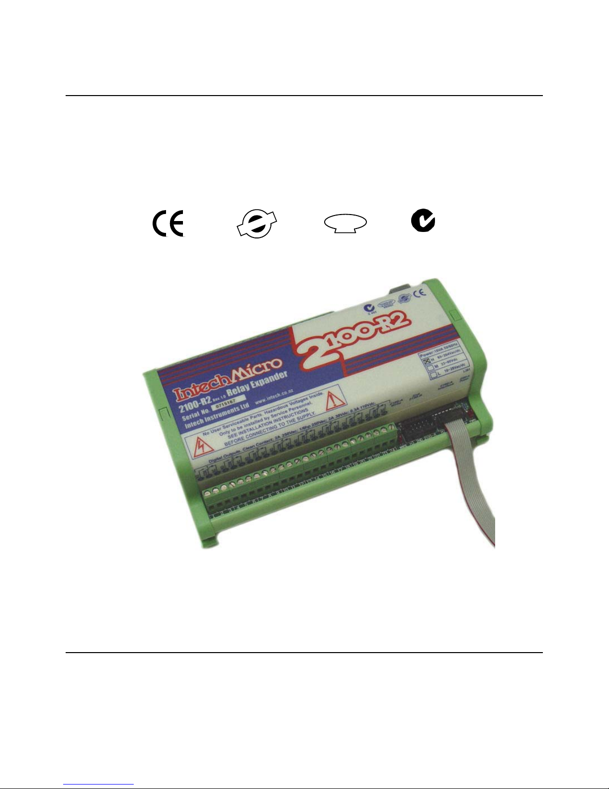
INTECH Micro
2100-R2 REV 1.0
Installation Guide.
14.08-1
TECHNOLOGY
& QUALITY
A
WAR
D
ISO9001
E
G
I
S
T
E
R
R
E
D
M
A
N
U
A
T
U
R
E
R
C
F
Z985

14.08-2
Section A. Description, Ordering and Specifications.
2100-R2 Installation Guide Index.
Section A. Description, Ordering and Specifications.
Index. Page 2
Features and Ordering Information. Page 3
Specifications. Page 4
Dimensions. Page 4
Terminals and layout. Page 5
Section B. Jumpers and LED Functions Tables.
H1 Power Supply Settings. Page 6
LED Descriptions. Page 6
Section C. Output Connection Diagrams.
2100-A4 Relay Output Expansion - Using 2100-R2 Relay Expansion. Page 7
2100-A16 Relay Output Expansion - Using 2100-R2 Relay Expansion. Page 8
2100-A16 Relay Output Allocation for Single Action Controllers. Page 9
Relay Output Connection Example for Single Action Controllers. Page 9
2100-A16 Relay Output Allocation Table for Dual Action Controllers. Page 10
Relay Output Connection Example for Dual Action Contollers - Single 2100-R2. Page 10
Relay Output Connection Example for Dual Action Contollers - Casdaded 2100-R2. Page 11
Section D. Wiring and Installation.
Mounting. Page 12
Cover Removal and Fitting. Page 12
Power Supply Wiring. Page 12
Analogue Signal Wiring. Page 12
Commissioning. Page 12
Software Programming Page 12
16 Channel Relay
Ouput Expander.
INTECH Micro
2100-R2
Rev 1.0
Features.
zz
zz
z 16 Digital, Isolated, Relay Outputs.
zz
zz
z Cascade option for a 2nd 2100-R2.
zz
zz
z Enables 32 Digital, Isolated, Relay Outputs.
zz
zz
z Cost Effective Output Expansion for 2100-A16 and 2100-A4.
zz
zz
z Easy Programming Via Microscan Maps.
zz
zz
z Programmable Relay States - NO or NC.
zz
zz
z Universal AC/DC Power Supply.
zz
zz
z Easy to Install.
zz
zz
z Compact DIN Rail Mount Enclosure
Ordering Examples.
1/ 2100-R2-M 2100-R2; 23~90Vdc Power Supply.
Quality Assurance Programme.
The modern technology and strict procedures of the ISO9001 Quality Assurance Programme applied during design,
development, production and final inspection grant long term reliability of the instrument. This instrument has been
designed and built to comply with EMC and Safety Standards requirements.
14.08-3
2R-0012rofsnoitpOgnignaR
lppuSrewoP
y
SP
)2(
cdV/caV462~58H
cdV09~32 M
cd/caV82~01L
Note 1) The 2100-R2-X is field selectable for H or M power supply.
Note 2) Power supply ‘H’ is field selectable for ’M’, and ‘M’ for ‘H’. Power supply ‘L’ must be ordered separately.
2100 models include:
2100-4S : RS422 to RS485 Converter.
2100-A16 :16AI, 4DI, 2 Relay Out, 2 AO.
2100-A4 :4AI, 4DI, 4 Relay Out, 2 AO.
2100-A4e :4AI, 4DI, 8 Relay Out, 2 AO.
2100-AO :8 AO, 8 AI, 12 DI, 2 Relay Out.
2100-D :12DI, 12 Relay Out.
2100-IS :Isolated RS232 to RS422/485.
2100-M :16AI Multiplexer.
2100-ME :Memory Expansion for 2100-A.
2100-NET :Isolated Ethernet to RS232/422/485.
2100-NS :Non-Isolated RS232 to RS422/485.
2100-R2 :16 Relay Expansion for 2100-A.
2100-RL2 :2 Relay Expansion for 2100-A.
TECHNOLOGY
& QUALITY
A
WAR
D
ISO9001
E
G
I
S
T
E
R
R
E
D
M
A
N
U
A
T
U
R
E
R
C
F
Description.
The 2100-R2 16 Channel Relay Output Expansion Module is used in conjunction with the 2100-A16.
This allows the 2100-A16 to stand alone as a 16 channel controller / alarm unit. A second 2100-R2 can
be then connected to the first 2100-R2, creating a 32 channel controller / alarm unit. The 2100-R2
relay outputs can be used for any combination of control and alarm functions. The control parameters
for each of the 16 controllers is downloaded from user friendly Microscan Sofware, and stored in
permanent memory on the 2100-A16. These parameters include Setpoint (SV), Switching Differential,
Auto / Manual, Manual Output Setting, Dual Action Control, Single Action Control, Heat / Cool, Heat
Only, Cool Only.
The 16 controller alarms will operate unaffected by computer power downs, reboots, etc. The relay
outputs can also be accessed directly from the Scada. The 2100-R2 can also be used in conjunction
with the 2100-A4 for general purpose alarms, generated by the Scada.
Ordering Information.
2100-R2-X Standard Unit: 85~264Vac/dc Power Supply.
2100-R2
PS
Z985

14.08-4
2100-R2 Dimensions.
2100-R2 Relay Expander2100-R2 Relay Expander
2100-R2 Relay Expander2100-R2 Relay Expander
2100-R2 Relay Expander
Serial No. Serial No.
Serial No. Serial No.
Serial No.
195m m
120m m
.
120mm
70
mm
2100-R2 Specifications.
Input: Interfaced with the 2100-A16 or 2100-A4.
Digital Outputs: 16 Individually Isolated Changeover Relays with LED Indication of Each Output.
-Functions When used with a 2100-A16, the relays can be used as Set Point (SV)
Switching Differential, Auto/Manual, Manual Output Setting, Dual Action Control,
Single Action Control, Heat/Cool, Cool Only, Heat Only.
-Contact Material Silver Alloy
-Relay Ratings Maximum Rating Approved to Standard
250Vac, 2A UL
125Vac, 2A CSA
110Vdc, 0.3A;
30Vdc, 2A;
250Vac,1/6hp;
125Vac, 1/10hp.
-Number of Operations 2 x 10⁵ Min, at 1A, 250Vac Resistive Load.
Power: -H 85~264Vac/dc; 50/60Hz; 10VA.
-M 23~90Vdc; 10VA.
-L 10~28Vac/dc; 50/60Hz; 10VA.
Refer to ‘2100-R2 H1 Power Supply Settings’ for voltage selection instructions.
Safety and EMC Compliances:
EMC Emissions Compliance EN 55022-A.
EMC Immunity Compliance EN 50082-1.
Safety Compliance EN 60950.
Mains Isolation 250Vac.
Mains Isolation Test Voltage -To all Inputs and Outputs: 3000Vac 50Hz for 1min.
-To Earth: 1500Vac 50Hz for 1min.
Isolation Test Voltages: -Interface to Outputs 3000Vac 50Hz for 1min.
-Between Outputs: 1500Vac 50Hz for 1min.
General Specifications: (Unless otherwise stated in other input specifications.)
RF Immunity <±1% Effect FSO Typical.
Operating Temperature 0~60C.
Storage Temperature -20~80C.
Operating Humidity 5~85%RH Max. Non-Condensing.
Housing -Material ABS Inflammability V0 (UL94)
-Dimensions L=195, W=120, H=70mm.
-Mounting 35mm Symmetrical Mounting Rail.
-Weight 800g. Includes Packaging.
Note 1. Contact INTECH INSTRUMENTS for more detailed programming information.
Product Liability. This information describes our product s. It does not constitute guaranteed properties and is not intended to af firm the suitability
of a product for a particular application. Due to ongoing research and development, designs, specifications, and documentation are subject to
change without notification. Regrettably, omissions and exceptions cannot be completely ruled out. No liability will be accepted for errors, omissions
or amendments to this specification. Technical data are always specified by their average values and are based on Standard Calibration Units at
25C, unless otherwise specified. Each product is subject to the ‘Conditions of Sale’.
Warning: These products are not designed for use in, and should not be used for p atient connected applications. In any critical installation
an independant fail-safe back-up system must always be implemented.
CAUTION: Dangerous Voltages may be present. The 2100-R2 has no user serviceable parts.
Protective enclosure only to be opened by qualified personnel.
Remove ALL power sources before removing protective cover.

14.08-5
2100-R2 Terminals and Layout.
NO
Relay 1 COM
NC
1
2
3
4
5
6
7
8
9
10
11
12
13
14
15
16
17
18
19
20
21
22
23
24
NO
Relay 2 COM
NC
NO
Relay 3 COM
NC
NO
Relay 4 COM
NC
NO
Relay 5 COM
NC
NO
Relay 6 COM
NC
NO
Relay 7 COM
NC
NO
Relay 8 COM
NC
H1: SUPPL Y VOLTAGE
SELECTOR
RELAY
OUT
RELAY
OUT
NC
COM Relay 9
NO
NC
COM Relay 10
NO
NC
COM Relay 11
NO
NC
COM Relay 12
NO
NC
COM Relay 13
NO
NC
COM Relay 14
NO
NC
COM Relay 15
NO
NC
COM Relay 16
NO
Power LED 1
WRITE
H3. 2nd 2100-R
Interface
Connector
Earth ( )
Neutral (-)
Phase (+)
POWER
25
26
27
28
29
30
31
32
33
34
35
36
37
38
39
40
41
42
43
44
45
46
47
48
80
81
82
H
H1
M
WARNING.
High V oltages May be
Present in This Area.
Only adjust jumpers with power OFF.
H2. A16
Interface
Connector
Intech
INSTRUMENTS LTD
www.intech.co.nz

snoitpircseDDEL
emaNDEL noitcnuFDEL
etirWA-0012 .atadlairesgniviecersi2R-0012nehwylnoevitcA
rewoPA-0012 .nosiylppusrewopA-0012setacidnI
rewoPR-0012.nosiylppusrewop2R-0012setacidnI
61~1tuptuO .dezigrenesiyalertuptuoevitcepserriehtnehwsetacidnI
sgnitteSrepmuJylppuSrewoP
1H egnaRegatloVylppuSrewoP
Hcd/caV462~58rofrepmuJ
M cdV09~32rofrepmuJ
14.08-6
2100-R2 H1 Power Supply Settings.
Note 1. Power must be OFF before changing H1’s position.
Note 2. Exceeding these parameters may damage the unit.
Note 3. Ensure the enclosure label is correctly labelled for the jumper position.
Note 4. Low Voltage Power Supply version is fixed, and has no jumper. This must be ordered separately.
2100-R2 LED Descriptions.
Section B. 2100-R2 Jumpers and LED Functions Tables.
* Refer to ‘2100-R2 Terminals and Layout’ for the location of the following jumpers.
CAUTION: Dangerous voltages may be present. The 2100-R2 has no user serviceable parts.
Protective enclosure only to be opened by qualified personnel.
Remove ALL power sources before removing protective cover.

.
H2 A16
Interface
H3 2ND
2100-R2
14.08-7
Section C. Output Connection Diagrams.
2100-A4 Relay Output Expansion - Using 2100-R2 Relay Expansion.
Output relay expansion is available using the 2100-R2, 16 relay output expansion module. These relay outputs can
only be used as general purpose alarms generated by the Scada.
Connecting the 2100-A4 to the 2100-R2.
1/ Power must be off before installing the 10 way ribbon cable and 2100-ARI
board supplied with the 2100-R2.
2/ Remove the cover off the 2100-A4.
3/ An exchange cover, with a precut slot for the ribbon cable, is available
free of charge from your supplier. P/N: 2100-A4-COVERSLOT.
Alternatively you may wish to modify the existing cover:
Cut a 1mm slot, 20mm deep, just below terminal numbers 1, 2 & 3.
Carefully smooth the edges of the cut so the ribbon cable does not get damaged.
4/ The 2100-ARI is supplied with the ribbon cable attached. Use antistatic precautions
when installing. Carefully orientate the 2100-ARI board as shown above. Locate the
two plastic standoffs over the corresponding holes in the 2100-A4, and the 10 pin
connector. Once all three are aligned, push the 2100-ARI firmly into the 2100-A4.
5/ Connect the other end of the cable to the 2100-R2, ‘H2 A16 Interface’ connector . Ensure both ends of the cable
are firmly connected.
6/ Slide the cable into the slot, and replace the cover on the 2100-A4.
7/ If a 2nd 2100-R2 is used, connect the ribbon cable from the ‘H3 2ND 2100-R2’ header on the first 2100-R2, to
the ‘H2 A16 Interface’ connector on the second 2100-R.
8/ The 2100-R2 must be enabled in the programming dialogue boxes. Advanced ‘2100-R2 Relay Expander’ options.
For detailed programming info, refer to
‘Programming 2100-Series Remote Station’ in the Microscan Manual.
9/ A 2100-R2 connected to the 2100-A4 must share the same power supply disconnect device and over current
device. Both units must be powered and unpowered at the same time to prevent indeterminate relay states.
WARNING: The 2100-ARI is ST A TIC SENSITIVE.
Only touch the edges of the PCB.
Ensure standoffs lock firmly into the 2100-A4 board.
2100-R2 Relay Expander2100-R2 Relay Expander
2100-R2 Relay Expander2100-R2 Relay Expander
2100-R2 Relay Expander
Serial No. Serial No.
Serial No. Serial No.
Serial No.
2100-ARI
2100-A4
A B B
INPUT 2
A B B
INPUT 1
1 2 3 4 5 6
1x20mm
SLOT
FIRST 2100-R2

..
H2 A16
Interface
H3 2ND
2100-R2
H2 A16
Interface
H3 2ND
2100-R2
14.08-8
Connecting the 2100-A16 to the 2100-R2.
1/ Power must be off before installing the 10 way ribbon cable and 2100-ARI
board supplied with the 2100-R2.
2/ Remove the cover off the 2100-A16.
3/ An exchange cover, with a precut slot for the ribbon cable, is available
free of charge from your supplier. P/N: 2100-A16-COVERSLOT.
Alternatively you may wish to modify the existing cover:
Cut a 1mm slot, 20mm deep, just below terminal numbers 1, 2 & 3.
Carefully smooth the edges of the cut so the ribbon cable does not get damaged.
4/ The 2100-ARI is supplied with the ribbon cable attached. Use antistatic precautions
when installing. Carefully orientate the 2100-ARI board as shown above. Locate the
two plastic standoffs over the corresponding holes in the 2100-A16, and the 10 pin
connector. Once all three are aligned, push the 2100-ARI firmly into the 2100-A16.
5/ Connect the other end of the cable to the 2100-R2. Ensure both ends of the cable are firmly connected.
6/ Slide the cable into the slot, and replace the cover on the 2100-A16.
7/ If a 2nd 2100-R2 is used, connect the ribbon cable from the ‘H3 2ND 2100-R2’ header on the first 2100-R2, to
the ‘H2 A16 Interface’ connector on the second 2100-R.
8/ The 2100-R2 must be enabled in the programming dialogue boxes. Advanced ‘2100-R2 Relay Expander’ options.
For detailed programming info, refer to
‘Programming 2100-Series Remote Station’ in the Microscan Manual.
9/ A 2100-R2 connected to the 2100-A16 must share the same power supply disconnect device and over current
device. Both units must be powered and unpowered at the same time to prevent indeterminate relay states.
2100-A16 Rev1.1 Relay Output Expansion - Using 2100-R2 Relay Expansion.
Output relay expansion is available using the 2100-R2, 16 relay output expansion module. This allows the 2100-A16 to
stand alone as a 16 channel controller / alarm unit. The 2100-R2 relay outputs can be used for any combination of control
and alarm functions. The control parameters for each of the 16 controllers is downloaded from user friendly Microscan
Software, and stored in permanent memory on the 2100-A16. These parameters include Setpoint (SV), Output Switching
Differential, Auto / Manual, Manual Output Setting, , Dual Action Control, Single Action Control, Heat / Cool, Heat Only,
Cool Only. The 16 controller / alarms will operate unaffected by computer power downs, reboots, etc. The relay outputs can
also be accessed directly from the Scada.
2100-R2 Relay Expander2100-R2 Relay Expander
2100-R2 Relay Expander2100-R2 Relay Expander
2100-R2 Relay Expander
Serial No.Serial No.
Serial No.Serial No.
Serial No.
2100-ARI
2100-A
16
A B B
INPUT 2
A B B
INPUT 1
1 2 3 4 5 6
1x20mm
SLOT
WARNING: The 2100-ARI is STATIC SENSITIVE.
Only touch the edges of the PCB.
Ensure standoffs lock firmly into the 2100-A16 board.
2100-R2 Relay Expander2100-R2 Relay Expander
2100-R2 Relay Expander2100-R2 Relay Expander
2100-R2 Relay Expander
Serial No.Serial No.
Serial No.Serial No.
Serial No.
FIRST 2100-R2
SECOND 2100-R2

14.08-9
2100-R2
1
2
3
NO
COM Relay 1
NC
4
5
6
NO
COM Relay 2
NC
7
8
9
NO
COM Relay 3
NC
10
11
12
NO
COM Relay 4
NC
13
14
15
NO
COM Relay 5
NC
1/6hp, 250Vac
Inductive
2A, 250Vac
Resistive
2A, 30Vdc
Resistive
2100-R2 Relay Output Connection Example for Single Action Controllers.
Note 1. With relays NOT energized, and ‘Normally Off’ st ate
selected (refer Note 3)
NO = Normally Open.
COM = Common.
NC = Normally Closed.
Heating Relay: NO, closes when heating required.
Cooling Relay: NO, closes when cooling required.
Note 2. All relays are change-over .
Note 3. Each relay can be configured for a ‘Normally ON’ or
‘Normally OFF’ output state. (E.g. for fail safe
operation.) The ‘Normally ON/OFF’ settings are
retained in software on power down, but the relays
are de-energized. The ‘Normally ON/OFF’ state of
the relay can be changed in the Advanced dialog
box for the onboard relays, or using the Relay States
dialog box for the 2100-R2. Refer to MicroScan
Configuration Manual.
Note 4. LED indication on each output when each
relay is energized.
Note 5. Single Action Setting is a global setting for the station.
COOLING
HEATING
noitarugifnoClortnoCtuptuOottupnI
rellortnoC tupnIeugolanA .oNyaleR .edoMlortnoC
11 1 ylnOlooCroylnOtaeH
2 2 2 ylnOlooCroylnOtaeH
33 3 ylnOlooCroylnOtaeH
4 4 4 ylnOlooCroylnOtaeH
55 5 ylnOlooCroylnOtaeH
6 6 6 ylnOlooCroylnOtaeH
77 7 ylnOlooCroylnOtaeH
8 8 8 ylnOlooCroylnOtaeH
99 9 ylnOlooCroylnOtaeH
01 01 01 ylnOlooCroylnOtaeH
111111ylnOlooCroylnOtaeH
21 21 21 ylnOlooCroylnOtaeH
313131ylnOlooCroylnOtaeH
41 41 41 ylnOlooCroylnOtaeH
515151ylnOlooCroylnOtaeH
61 61 61 ylnOlooCroylnOtaeH
2100-R2 with 2100-A16 Relay Output Allocation Table for Single Action Controller.
16 controllers, one relay per controller.

14.08-10
2100-R2 Relay Output Connection Example for Dual Action Contollers - Single 2100-R2.
2100-R2
25
26
27
NC
Controller 5
COM
(Relay 9)
NO
28
29
30
31
32
33
34
35
36
NC
Controller 5
COM
(Relay 10)
NO
NC
Controller 6
COM
(Relay 11)
NO
NC
Controller 6
COM
(Relay 12)
NO
1
2
3
NO
Controller 1
COM
(Relay 1)
NC
4
5
6
NO
Controller 1
COM
(Relay 2)
NC
Power
1
2
3
NO
Controller 2
COM
(Relay 3)
NC
4
5
6
NO
Controller 2
COM
(Relay 4)
NC
Note 1. With relays NOT energized, and ‘Normally Off’ state selected (refer Note 3)
NO = Normally Open. COM = Common. NC = Normally Closed.
Heating Relay: NO, closes when heating required. Cooling Relay: NO, closes when cooling required.
Note 2. All relays are change-over.
Note 3. Each relay can be configured for a ‘Normally ON’ or ‘Normally OFF’ output state. (E.g. for fail safe operation.)
The ‘Normally ON/OFF’ settings are retained in software on power down, but the relays are de-energized.
The ‘Normally ON/OFF’ state of the relay can be changed in the Advanced dialog box for the onboard relays,
or using the Relay St ates dialog box for the 2100-R2. Refer to MicroScan Configuration Manual.
Note 4. LED indication on each output when each relay is energized.
Note 5. In Dual Action mode, if the controller is set to heat only, the cool relay is always off. If the controller is set to
cool only , the heat relay is always off. Likewise when using Manual Mode in the heat only mode, only the sta te
of the heat relay can be changed, and on the cool only mode, only the state of the cool relay can be changed.
Note 6. Dual Action Setting is a global setting for the station.
HEATING 2
HEATING 1
HEATING 5
HEATING 6
COOLING 1
COOLING 2
COOLING 5
COOLING 6
noitarugifnoClortnoCtuptuOottupnI
rellortnoC
eugolanA
tupnI
yaleR
noitcAlortnoC
yaleRylnOtaeH
noitcAlortnoC
yaleRylnOlooC
noitcAlortnoC
yaleRlooC/taeH
11
11 taeH1
22looC2
2 2
3 3 taeH3
4 4 looC4
3 3
55 taeH5
66looC6
4 4
7 7 taeH7
8 8 looC8
5 5
99 taeH9
0101looC01
6 6
11 11 taeH11
21 21 looC21
7 7
3131taeH31
4141looC41
8 8
51 51 taeH51
61 61 looC61
2100-R2 with 2100-A16 Relay Output Allocation for Dual Action Controller.
Eight controllers, two relays per controller.

14.08-11
2100-R2 Relay Output Connection Example for Dual Action Contollers - Cascaded 2100-R2s.
Note 1. With relays NOT energized, and ‘Normally Off’ st ate selected (refer Note 3)
NO = Normally Open. COM = Common. NC = Normally Closed.
Heating Relay: NO, closes when heating required. Cooling Relay: NO, closes when cooling required.
Note 2. All relays are change-over.
Note 3. Each relay can be configured for a ‘Normally ON’ or ‘Normally OFF’ output state. (E.g. for fail safe operation.)
The ‘Normally ON/OFF’ settings are retained in software on power down, but the relays are de-energized.
The ‘Normally ON/OFF’ state of the relay can be changed in the Advanced dialog box for the onboard relays,
or using the Relay States dialog box for the 2100-R2. Refer to MicroScan Configuration Manual.
Note 4. LED indication on each output when each relay is energized.
Note 5. In Dual Action mode, if the controller is set to heat only, the cool relay is always off. If the controller is set to
cool only , the heat relay is always off. Likewise when using Manual Mode in the heat only mode, only the sta te
of the heat relay can be changed, and on the cool only mode, only the state of the cool relay can be changed.
Note 6. Dual Action Setting is a global setting for the station.
2100-R2 (Second)
25
26
27
NC
Controller 13
COM
(Relay 9)
NO
28
29
30
31
32
33
NC
Controller 13
COM
(Relay 10)
NO
NC
Controller 14
COM
(Relay 11)
NO
1
2
3
NO
Controller 9
COM
(Relay 1)
NC
4
5
6
NO
Controller 9
COM
(Relay 2)
NC
Power
1
2
3
NO
Controller 10
COM
(Relay 3)
NC
H3 2ND
2100-R2
H2 A16
Interface
2100-R2 (First)
25
26
27
NC
Controller5
COM
(Relay 9)
NO
28
29
30
31
32
33
NC
Controller 5
COM
(Relay 10)
NO
NC
Controller 6
COM
(Relay 11)
NO
1
2
3
NO
Controller 1
COM
(Relay 1)
NC
4
5
6
NO
Controller 1
COM
(Relay 2)
NC
1
2
3
NO
Controller 2
COM
(Relay 3)
NC
HEATING 2
HEATING 1
HEATING 5
HEATING 6
H3 2ND
2100-R2
H2 A16
Interface
To 2100-A16
HEATING 9
COOLING 5
COOLING 1
COOLING 9
12
12
HEATING 10
COOLING 13
HEATING 13
HEATING 14

2100-R2-r1 250108.p65
14.08-12
Section D. Wiring and Installation.
2100-R2 Wiring and Installation.
THE 2100-R2 IS TO BE INSTALLED AND SERVICED BY SERVICE PERSONNEL ONLY. NO OPERATOR / USER SERVICEABLE PARTS.
All power and signals must be de-energised before connecting any wiring, or altering any Jumpers or Dip Switches.
Mounting.
* Also refer to Connection Diagrams and Notes.
(1) Mount in a clean environment in an electrical cabinet on 35mm symmetrical mounting rail.
(2) Draft holes must have minimum free air space of 20mm. Foreign matter must not enter or block draft holes.
(3) Do not subject to vibration or excess temperature or humidity variations.
(4) Avoid mounting in cabinets with power control equipment.
(5) To maintain compliance with the EMC Directives the 2100-R2 is to be mounted in a fully enclosed steel fire
cabinet. The cabinet must be properly earthed, with appropriate input / output entry points and cabling.
Cover Removal and Fitting.
To remove 2100 covers, firmly push down the button in the middle of one endplate, and pull the end plate outwards, while
pulling the cover up and out.
To fit the cover, first make sure the cover is being fitted the correct way around, (Terminal 82 on the cover is above 82
on the board.) and that the serial number on the board matches the serial number on the cover (if applicable). Slide one
end of the cover into the slot in the endplate. Pull the other endplate outwards and push the cover down until it slides into
the slot of this endplate. Check both ends are firmly held.
Power Supply Wiring.
(1) A readily accessible disconnect device and a 1A, 250Vac overcurrent device, must be in the power supply wiring.
(2) Any 2100-A connected to the 2100-R2, must share the same disconnect device and overcurrent device
(3) For power supply, connect Phase (or +Ve) to terminal 82, Neutral (or -Ve) to 81, and Earth to 80. To ensure
compliance to CE Safety requirements, the grey terminal insulators must be fitted to ALL mains terminals after
wiring is completed. (ie. terminals 82, 81 and 80.) For Non Hazardous Voltage power supplies (not exceeding
42.4Vpeak or 60Vdc) terminals 81 and 80 may be linked together, instead of connecting an earth.
Analogue Signal Wiring.
(1) All signal cables should be good quality overall screened INSTRUMENTATION CABLE with the screen earthed
at one end only.
(2) Signal cables should be laid a minimum distance of 300mm from any power cables.
(3) For 2 wire current loops, 2 wire voltage signals or 2 wire current signals, Austral Standard Cables B5102ES is
recommended. For 3 wire transmitters and RTDs Austral Standard Cables B5103ES is recommended.
(4) It is recommended that you do not ground current loops and use power supplies with ungrounded outputs.
(5) Lightning arrestors should be used when there is a danger from this source.
(6) Refer to diagrams for connection information.
Commissioning.
(1) Check that all the above conditions have been met, and the wiring checked, before applying power to the 2100-R2.
(2) Check each relay output functions correctly, and the relay specifications are not being exceeded.
(3) Check each digital input functions correctly, and the digital input specifications are not being exceeded.
2100-R2 Software Programming.
The 2100-R2 software setup is accessed via the attached 2100-A16 programming boxes, and associated Station Map.
Refer to the 2100-A16 Installation Guide, and ‘Programming 2100 Series Remote Station’ in the Microscan Manual.
CAUTION: Dangerous voltages may be present. The 2100-R2 has no user serviceable parts.
Protective enclosure only to be opened by qualified personnel.
Remove ALL power sources before removing protective cover.
Intech
INSTRUMENTS LTD
www.intech.co.nz
Christchurch Ph: +64 3 343 0646
Auckland Ph: 09 827 1930
Email:
sales@intech.co.nz
 Loading...