

Page 1
CI-24 – Installation
Specifications subject to change without notice. | 86-0468-00r3 9/99 | USA 150729 | Page 1 of 8
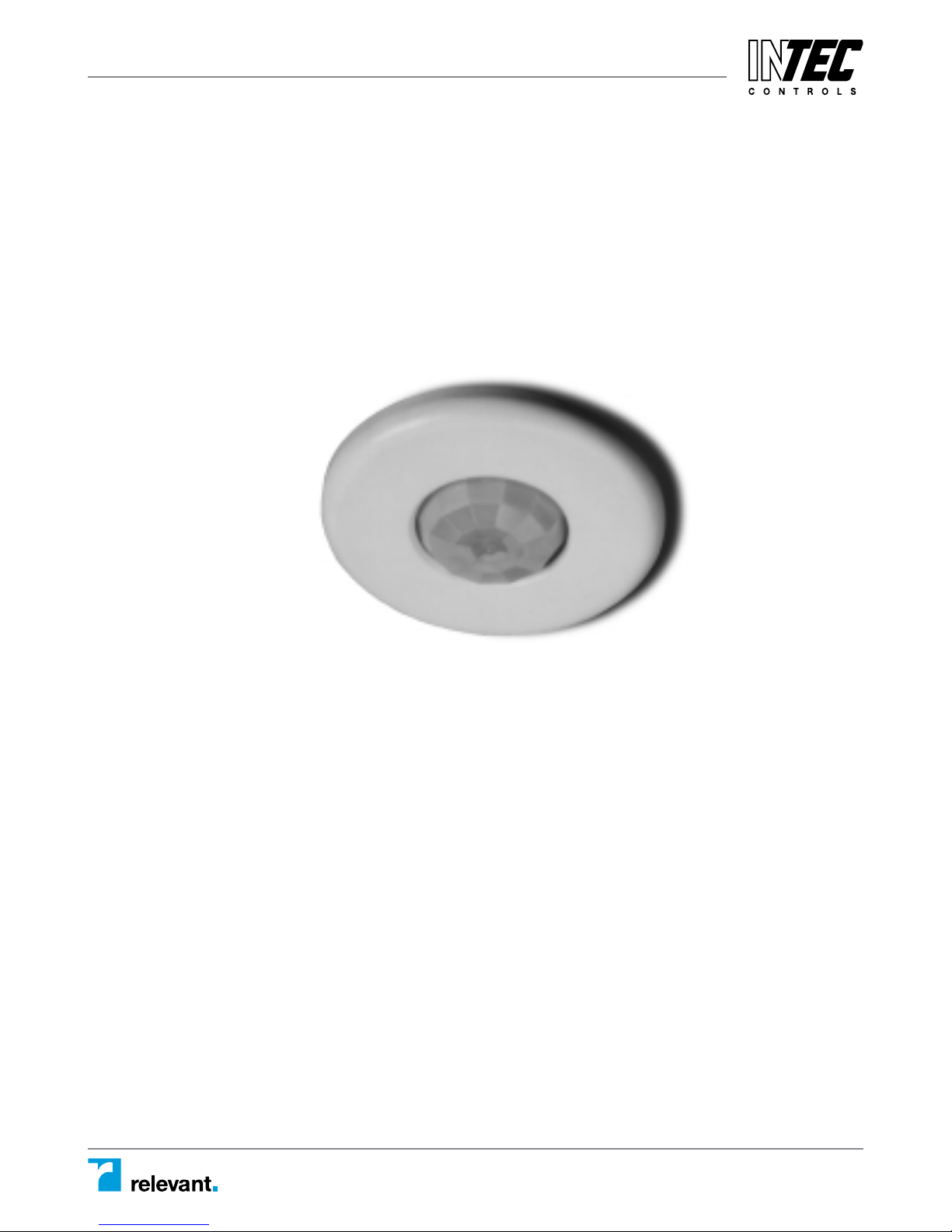
360° PIR Occupancy Sensor
CI-24
SPECIFICATIONS
Voltages . . . . . . . . . . . . . . . . . . . . . . . 24VAC or 24VDC, ±10%
Current Consumption . . . . . . . . . . . . . @24VAC, 37mA Maximum
@24VDC, 30mA Maximum
Isolated Relay Rating . . . . . . . . . . . . . . . . 1A @24VDC or 24VAC
Time Adjustment . . . . . . . . . . . . . . . . . . . 30 seconds–30 minutes
Sensitivity Adjustment . . . . . . . . . . . . . . . . . . Minimum/Maximum
12700 Stowe Drive, Suite 100, Poway, CA 92064 | Ph: (858) 578.7887 & (888) GO.INTEC | relevantsolutions.com/inteccontrols
Page 2
PLACEMENT
The effective coverage distances may be slightly less than the maximum sens-
ing distance (see Coverage Patterns), depending upon obstacles such as fur-
niture or partitions, and this must be considered when planning the number of
sensors and their positioning. See the list below for approximate coverage dis-
tances for different types of motion.
Approximate coverage, for a mounting height of 8 feet:
Lens option
Walking motion Workstation (hand motion)
Extended Range up to 22 ft radius (1200 sq ft) 12ft radius (500 sq ft)
High Density up to 12 ft radius (500 sq ft) 9ft radius (300 sq ft)
The CI-24 sensor can be mounted at various heights. When you will be
mounting at heights other than 8 feet, be aware that as you decrease the
mounting height, you will decrease the range and increase the sensitivity to
smaller motions. Conversely, when you increase the height, you will increase
the range and decrease the sensitivity to smaller motions. At heights of more
than 12-14 feet, you may start to significantly reduce sensitivity.
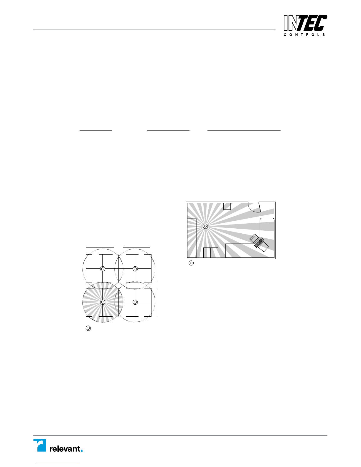
Often the best location to install a
CI-24 in a closed office is off-center
(see fig.1). Avoid placing a sensor
directly in line with an open door in
which it has a clear view out, as the
sensor may detect people walking by.
For open office areas with partitions it is
best to place sensors over intersections of
four workstations (see fig. 2).
Also avoid placing the sensors close to
air ducts, as rapid air currents or the
differences in temperatures may cause
false activations. For large areas of coverage
use multiple sensors.
CI-24
36'
36'
18'
fig. 1
fig. 2
CI-24 – Installation
Specifications subject to change without notice. | 86-0468-00r3 9/99 | USA 150729 | Page 2 of 8
DESCRIPTION
The CI-24 is a 24VAC or 24VDC Passive Infrared (PIR) occupancy sensor
which integrates with HVAC or EMS systems. The CI-24 provides isolated relay
contacts that are Normally Open or Normally Closed, based on occupancy.
PIR sensing systems are passive systems which react to changes in infrared
energy (moving body heat) within the coverage area. PIR sensors must directly
“see” motion of an occupant to detect them, so careful consideration must be
given to sensor placement.
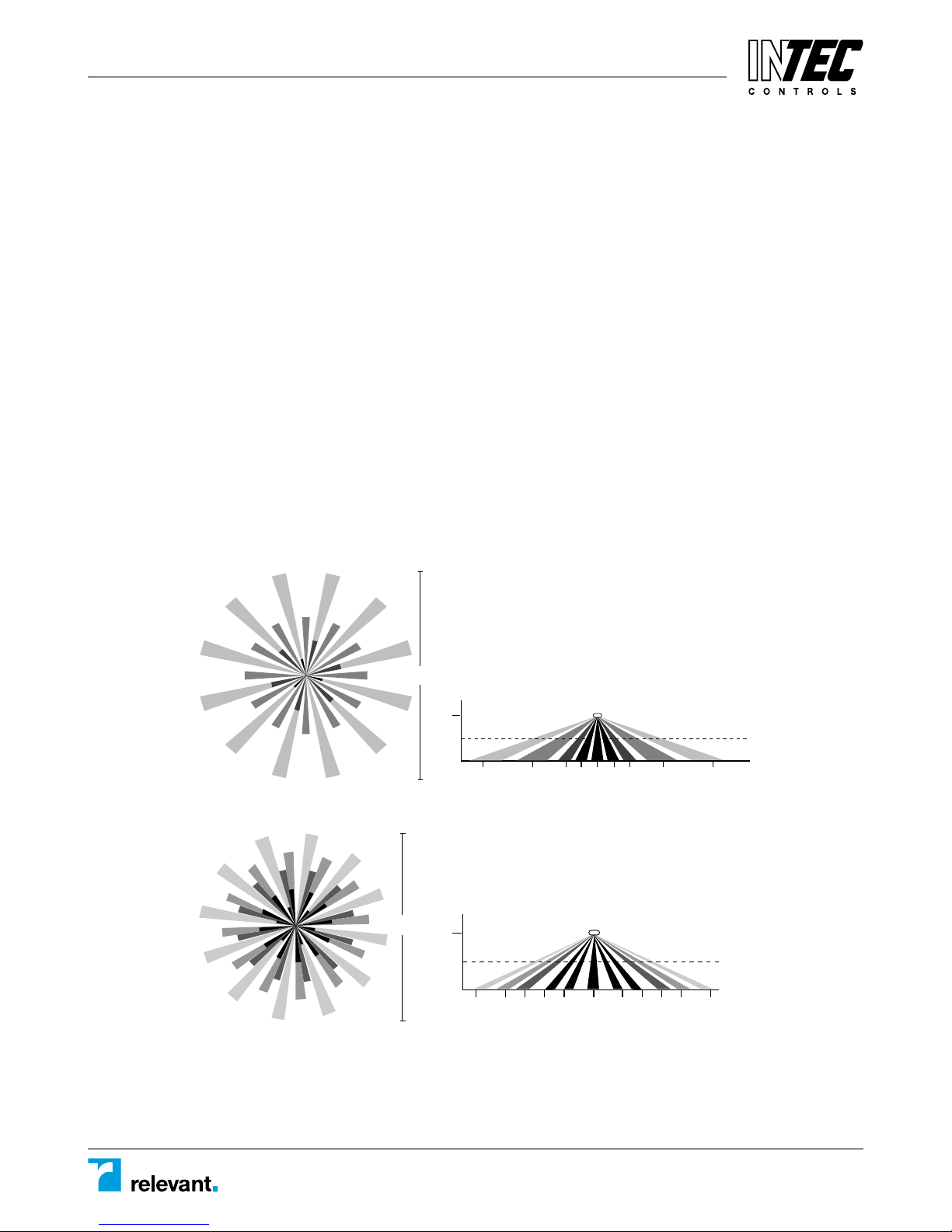
COVERAGE PATTERNS
The CI-24 has a multi-cell, multi-tier Fresnel lens with a field of view of 360°.
The sensor has two lens pattern options. The Extended Range Lens will cover
up to 1200 sq ft and 22 feet from the sensor when mounted at 8 feet. The
High Density/Reduced Range Lens will cover up to 500 sq ft and 12 feet from
the sensor when mounted at 8 feet.
Coverage shown in the diagrams below is maximum and represents coverage
for half-step, walking motion, with no barriers or obstacles.
DRAWING NOT TO SCALE
44 ft
Extended Range Lens (Standard)
CI-24
8 ft
Typical
desk-top
level
22 ft 13 ft 7 ft 3 ft 0 3 ft 7 ft 13 ft 22 ft
12700 Stowe Drive, Suite 100, Poway, CA 92064 | Ph: (858) 578.7887 & (888) GO.INTEC | relevantsolutions.com/inteccontrols
24 ft
High Density/Reduced Range Lens
CI-24-1
8 ft
Typical
desk-top
level
12 ft 12 ft 3 ft 3 ft 5 ft 5 ft 7 ft 7 ft 9 ft 9 ft0
Page 3
WIRING DIRECTIONS
≠CAUTION≠
TURN POWER OFF AT CIRCUIT BREAKER BEFORE WIRING SENSOR
• Connect 24VAC or +24VDC Supply to the RED and Return to the BLACK
wire from the sensor.
Isolated Relay: (Rated for 1A @24VDC or 24VAC)
Connect the wires necessary to the application that requires this output.
• GREEN (Normally Closed)—Open when occupancy is detected
• ORANGE (Common) (must be used for proper operation)
• YELLOW (Normally Open)—Closed when occupancy is detected
24VAC or +24VDC, ±10% RED
24VAC or 24VDC Return BLACK
Isolated Relay Outputs
Normally Closed Contact GREEN
Common ORANGE
Normally Open Contact YELLOW
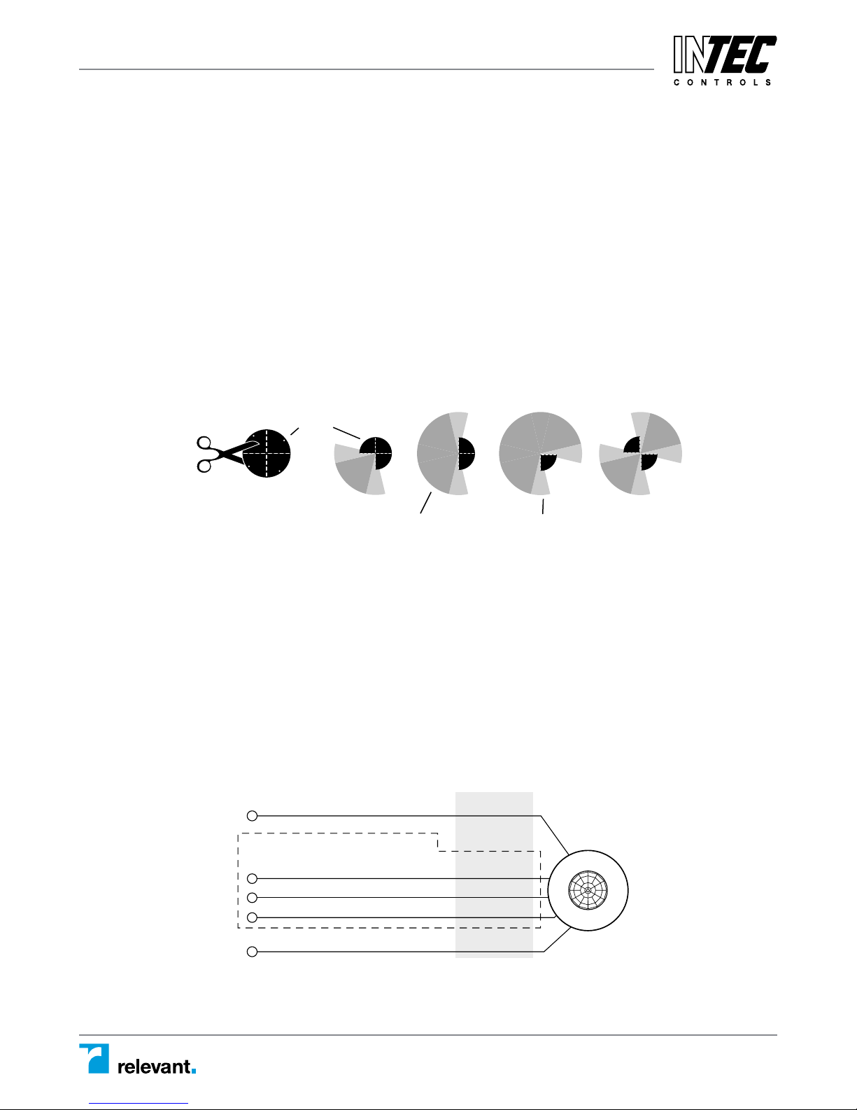
MASKING
An insert (mask) is supplied to allow elimination of coverage in unwanted areas.
The mask is cut as needed and mounted onto anchor pins in the sensor’s cover.
IMPORTANT: Do not use the mask if full coverage is desired.
IMPORTANT: Before securing the sensor in the mounting location, the
assembled sensor must be turned so the unmasked portion of the lens
faces the coverage area (the blue masked area is visible through the lens).
IMPORTANT: For an already installed sensor—If the sensor can NOT be turned,
then the mask must be cut so that when installed it will be oriented correctly
(note the location of the securing pins in the cover and note that the cover
turns as it locks into position).
Note: At the edges of the masking, there is a small area of reduced sensitivity,
illustrated as the lighter area in the examples below.
Cut mask into sections
for desired coverage,
shown right.
Mask
CI-24 – Installation
Specifications subject to change without notice. | 86-0468-00r3 9/99 | USA 150729 | Page 3 of 8
INSTALLATION
TURN POWER OFF AT CIRCUIT BREAKER BEFORE INSTALLING SENSOR
≠CAUTION≠
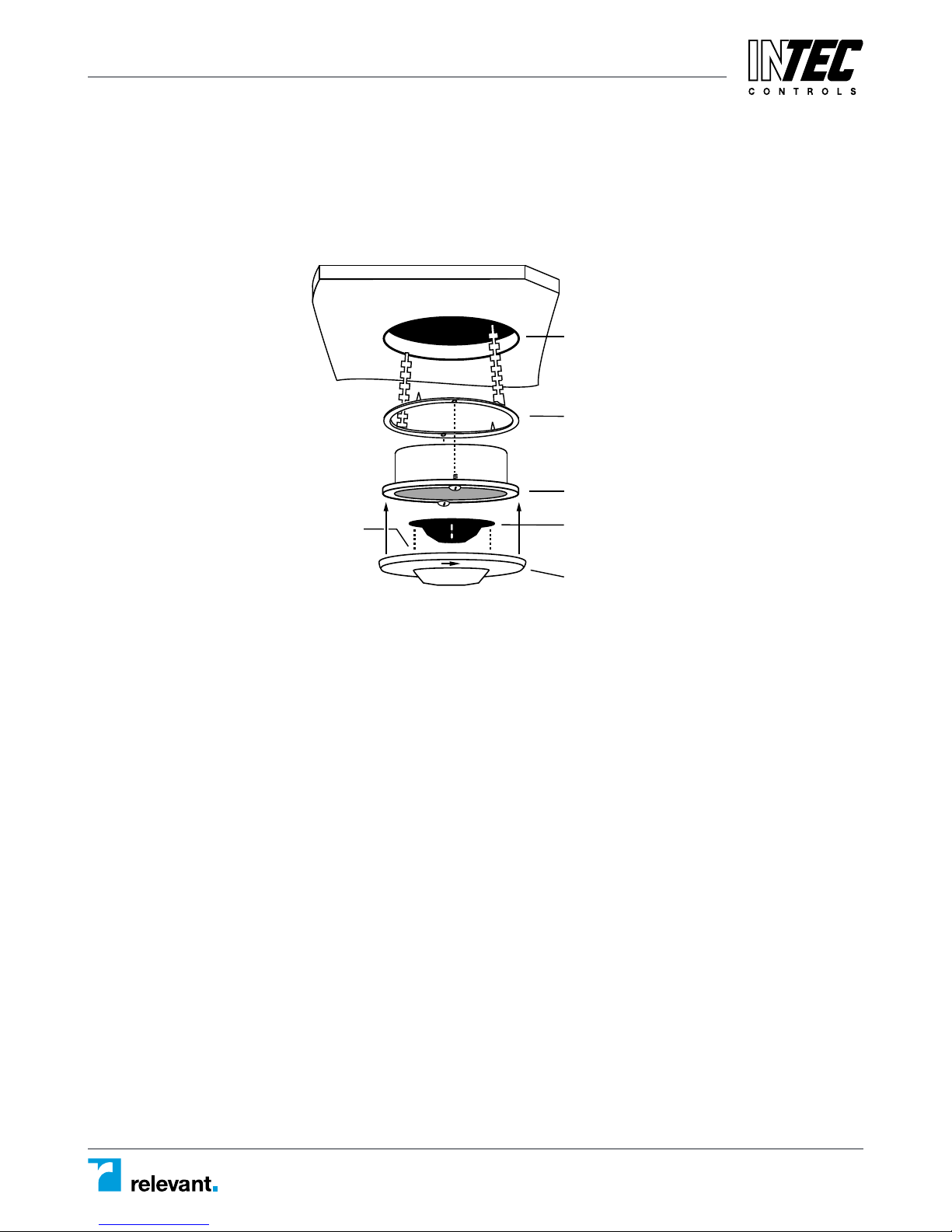
Ceiling
Mask secures
to pins on cover
2-3/4" to 3" hole
(if using 3" mud-ring,
cut to accomodate)
Ceiling attachment ring
(bend behind ceiling
to secure)
Rear housing
Mask (optional)
cut for desired coverage
Cover (with lens)
A 4-S junction box can be used with a 3" mud-ring when local building codes
mandate that low voltage connections be contained in a junction box.
Otherwise a 3" mud-ring or the pr
IMPORTANT: If the lens will be masked, the junction box or mud ring may
need to be positioned so that the mask is oriented properly when the sensor is
installed (see Masking).
Cut a hole in the ceiling tile—if using a:
• Ceiling attachment ring (provided)—cut about 2-3/4" to 3" in diameter.
• 3" mud ring—cut the hole to accommodate.
To assemble the sensor:
1. If using the ceiling attachment ring, bend the securing straps up so the sensor
housing can be inserted, and attach it to the sensor with the provided screws.
2. Attach the mask, if using, into the lens recess and onto the securing pins of
the cover.
3. Attach the cover to the rear housing—align tabs on inside of cover to
notches on outside perimeter of rear housing, place cover on sensor, and
twist clockwise to lock.
4. Insert the assembled sensor into the ceiling hole, and if using the mask,
turn the sensor so that the unmasked part of the lens is toward and centered on the area to be covered.
5. Bend the ceiling attachment ring straps behind the hole to secure (or
attach sensor to mud ring with screws).
ovided ceiling attachment ring can be used.
12700 Stowe Drive, Suite 100, Poway, CA 92064 | Ph: (858) 578.7887 & (888) GO.INTEC | relevantsolutions.com/inteccontrols
Page 4
TROUBLESHOOTING
≠CAUTION≠
USE PROPER SAFETY PRECAUTIONS WHEN
WORKING WITH OR NEAR HIGH VOLTAGE
LED does not flash with motion:
1. Determine if the lens is masked in the direction being tested (see Masking).
2. Check that the Sensitivity setting is set to maximum (DIP switch #3 to ON).
3. Check that the RED and BLACK wire connections from sensor are secure.
4. Check that 24VAC or 24VDC is between the RED and BLACK wire from the sensor.
• If it is present, the problem may be with the sensor. Try another sensor
(if available).
Isolated relay not functioning properly:
1. Check that Time Delay settings are correct (DIP switches #1 and 2).
2. Check Sensitivity setting. Also see Unwanted Sensor Activations, below.
3. Check that all wire connections from sensor are correct and secure.
4. Using proper precautions, check that there is voltage to the isolated relay.
5. Check that 24VAC or 24VDC is between the RED and BLACK wire from the sensor.
6. Use an ohmmeter to check the function of the isolated relay:
• Turn off the power connected to the isolated relay wires (if applicable).
- With motion in front of the sensor’s lens, check that the connection
between the GREEN and ORANGE wires is open.
- With motion in front of the sensor’s lens, check that the connection
between the YELLOW and ORANGE wires is closed.
• Turn Sensitivity and Time Delay to minimum, cover the sensor’s lens with
a cloth (not your hand), be still and allow the sensor to time-out.
- Check that the connection between the GREEN and ORANGE wires is closed.
- Check that the connection between the YELLOW and ORANGE wires is open.
Unwanted sensor activations (LED flashes):
Possible causes
1. People moving or walking outside of the desired coverage area, but in view
of the sensor and within it’s range (see Coverage Patterns and Placement).
2. HVAC vents with heavy air flow.
Possible solutions
1. Masking (see Masking).
2. Setting the Sensitivity to minimum if necessary (DIP switch #3).
3. Relocating the sensor.
Sensor Override:
If the sensor fails, set DIP switch #4 to Override position (DIP Switch # 4 to ON).
This overrides the sensor and sets the circuits to “on”.
CI-24 – Installation
Specifications subject to change without notice. | 86-0468-00r3 9/99 | USA 150729 | Page 4 of 8
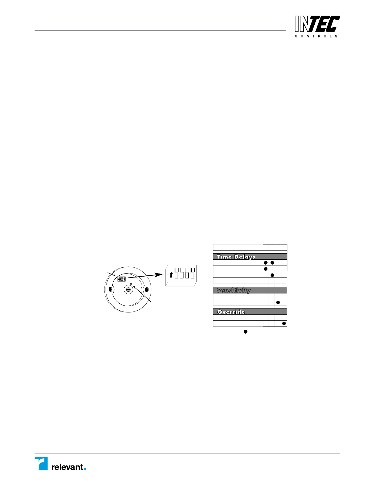
SENSOR ADJUSTMENT
The sensor comes factory preset and ready for operation.
If testing of operation is desired:
• Remove the sensor’s cover (twist).
• Refer to the DIP switch settings chart below for switch configurations.
• Make sure that office furniture and fixtures are in place.
1. Confirm the Override DIP switch is set to Normal (DIP switch #4 to OFF)
2. Restore power and turn on the system interfacing with the Isolated Relay.
• There is a one minute warm-up when power is initially restored to the
sensor before the sensor works properly.
3. Set Time Delay to minimum: DIP switches #1 and 2 to ON (30 seconds).
4. Set Sensitivity to maximum: DIP switch #3 to ON.
5. Replace the sensor’s cover.
6. Move away from sensor and be still. The sensor should time-out after
30 seconds and the isolated relay contacts should return to their “normal”
condition (Normally Open or Closed), see Wiring Directions diagram.
Note: If the sensor does not time-out or the isolated relay does not return to
its normal condition, move farther away or out of sight of the sensor, or see
Unwanted Sensor Activations under Troubleshooting.
7. Reset the Time Delay to the desired delay (DIP switches #1 and 2).
DIP SWITCH SETTINGS
DIP Switch Control
for Time Delay,
Sensitivity, and
Override
DIP Switch #
1234
1234
ON
ON
LED
30 seconds
10 minutes
20 minutes
30 minutes
.
Sensitivity
Minimum
.
.
Maximum
Normal
Override
.=Factory Presets
1234
–
–
–
–
–
–
=ON – =OFF
12700 Stowe Drive, Suite 100, Poway, CA 92064 | Ph: (858) 578.7887 & (888) GO.INTEC | relevantsolutions.com/inteccontrols
Page 5
18'
A 4-S junction box can be used with a 3" mud-ring when local building codes
mandate that low voltage connections be contained in a junction box.
Otherwise a 3" mud-ring or the pr
ovided ceiling attachment ring can be used.
IMPORTANT: If the lens will be masked, the junction box or mud ring may
need to be positioned so that the mask is oriented properly when the sensor is
installed (see Masking).
Cut a hole in the ceiling tile—if using a:
• Ceiling attachment ring (provided)—cut about 2-3/4" to 3" in diameter.
• 3" mud ring—cut the hole to accommodate.
To assemble the sensor:
1. If using the ceiling attachment ring, bend the securing straps up so the sensor
housing can be inserted, and attach it to the sensor with the provided screws.
2. Attach the mask, if using, into the lens recess and onto the securing pins of
the cover.
3. Attach the cover to the rear housing—align tabs on inside of cover to
notches on outside perimeter of rear housing, place cover on sensor, and
twist clockwise to lock.
4. Insert the assembled sensor into the ceiling hole, and if using the mask,
turn the sensor so that the unmasked part of the lens is toward and cen-
tered on the area to be covered.
5. Bend the ceiling attachment ring straps behind the hole to secure (or
attach sensor to mud ring with screws).
Ceiling
Mask secures
to pins on cover
INSTALLATION
≠CAUTION≠
TURN POWER OFF AT CIRCUIT BREAKER BEFORE INSTALLING SENSOR
CI-24 – Installation
Specifications subject to change without notice. | 86-0468-00r3 9/99 | USA 150729 | Page 5 of 8
PLACEMENT
The effective coverage distances may be slightly less than the maximum sensing distance (see Coverage Patterns), depending upon obstacles such as furniture or partitions, and this must be considered when planning the number of
sensors and their positioning. See the list below for approximate coverage distances for different types of motion.
Approximate coverage, for a mounting height of 8 feet:
Lens option
Extended Range up to 22 ft radius (1200 sq ft) 12ft radius (500 sq ft)
High Density up to 12 ft radius (500 sq ft) 9ft radius (300 sq ft)
The CI-24 sensor can be mounted at various heights. When you will be
mounting at heights other than 8 feet, be aware that as you decrease the
mounting height, you will decrease the range and increase the sensitivity to
smaller motions. Conversely, when you increase the height, you will increase
the range and decrease the sensitivity to smaller motions. At heights of more
than 12-14 feet, you may start to significantly reduce sensitivity.
Often the best location to install a
CI-24 in a closed office is off-center
(see fig.1). Avoid placing a sensor
directly in line with an open door in
which it has a clear view out, as the
sensor may detect people walking by.
36'
Walking motion Workstation (hand motion)
fig. 1
12'
CI-24
fig. 2
36'
CI-24
For open office areas with partitions it is
best to place sensors over intersections of
four workstations (see fig. 2).
Also avoid placing the sensors close to
air ducts, as rapid air currents or the
differences in temperatures may cause
false activations. For large areas of coverage
use multiple sensors.
12700 Stowe Drive, Suite 100, Poway, CA 92064 | Ph: (858) 578.7887 & (888) GO.INTEC | relevantsolutions.com/inteccontrols
Page 6
CI-24 – Installation
Specifications subject to change without notice. | 86-0468-00r3 9/99 | USA 150729 | Page 6 of 8
MASKING
An insert (mask) is supplied to allow elimination of coverage in unwanted areas.
The mask is cut as needed and mounted onto anchor pins in the sensor’s cover.
IMPORTANT: Do not use the mask if full coverage is desired.
IMPORTANT: Before securing the sensor in the mounting location, the
assembled sensor must be turned so the unmasked portion of the lens
faces the coverage area (the blue masked area is visible through the lens).
IMPORTANT: For an already installed sensor—If the sensor can NOT be turned,
then the mask must be cut so that when installed it will be oriented correctly
(note the location of the securing pins in the cover and note that the cover
turns as it locks into position).
Note: At the edges of the masking, there is a small area of reduced sensitivity,
illustrated as the lighter area in the examples below.
Mask
Cut mask into sections
for desired coverage,
shown right.
Coverage area
Reduced sensitivity
WIRING DIRECTIONS
≠CAUTION≠
TURN POWER OFF AT CIRCUIT BREAKER BEFORE WIRING SENSOR
• Connect 24VAC or +24VDC Supply to the RED and Return to the BLACK
wire from the sensor.
Isolated Relay: (Rated for 1A @24VDC or 24VAC)
Connect the wires necessary to the application that requires this output.
• GREEN (Normally Closed)—Open when occupancy is detected
• ORANGE (Common) (must be used for proper operation)
• YELLOW (Normally Open)—Closed when occupancy is detected
Wires
24VAC or +24VDC, ±10% RED
Isolated Relay Outputs
Normally Closed Contact GREEN
Common ORANGE
Normally Open Contact YELLOW
CI-24
Sensor
24VAC or 24VDC Return BLACK
12700 Stowe Drive, Suite 100, Poway, CA 92064 | Ph: (858) 578.7887 & (888) GO.INTEC | relevantsolutions.com/inteccontrols
Page 7

ORDERING INFORMATION
Catalog# Description
CI-24 24VAC or 24VDC Occupancy Sensor
with Extended Range Lens (Standard)
CI-24-1 24VAC or 24VDC Occupancy Sensor
with High Density /Reduced Range Lens
CI-12 12VDC Occupancy Sensor
with Extended Range Lens (Standard)
CI-12-1 12VDC Occupancy Sensor
with High Density /Reduced Range Lens
CI-24 – Installation
Specifications subject to change without notice. | 86-0468-00r3 9/99 | USA 150729 | Page 7 of 8
TROUBLESHOOTING
LED does not flash with motion:
1. Determine if the lens is masked in the direction being tested (see Masking).
2. Check that the Sensitivity setting is set to maximum (DIP switch #3 to ON).
3. Check that the RED and BLACK wire connections from sensor are secure.
4. Check that 24VAC or 24VDC is between the RED and BLACK wire from the sensor.
• If it is present, the problem may be with the sensor. Try another sensor
(if available).
Isolated relay not functioning properly:
1. Check that Time Delay settings are correct (DIP switches #1 and 2).
2. Check Sensitivity setting. Also see Unwanted Sensor Activations, below.
3. Check that all wire connections from sensor are correct and secure.
4. Using proper precautions, check that there is voltage to the isolated relay.
5. Check that 24VAC or 24VDC is between the RED and BLACK wire from the sensor.
6. Use an ohmmeter to check the function of the isolated relay:
• Turn off the power connected to the isolated relay wires (if applicable).
- With motion in front of the sensor’s lens, check that the connection
- With motion in front of the sensor’s lens, check that the connection
• Turn Sensitivity and Time Delay to minimum, cover the sensor’s lens with
a cloth (not your hand), be still and allow the sensor to time-out.
- Check that the connection between the GREEN and ORANGE wires is closed.
- Check that the connection between the YELLOW and ORANGE wires is open.
≠CAUTION≠
USE PROPER SAFETY PRECAUTIONS WHEN
WORKING WITH OR NEAR HIGH VOLTAGE
between the GREEN and ORANGE wires is open.
between the YELLOW and ORANGE wires is closed.
Unwanted sensor activations (LED flashes):
Possible causes
1. People moving or walking outside of the desired coverage area, but in view
of the sensor and within it’s range (see Coverage Patterns and Placement).
2. HVAC vents with heavy air flow.
Possible solutions
1. Masking (see Masking).
2. Setting the Sensitivity to minimum if necessary (DIP switch #3).
3. Relocating the sensor.
Sensor Override:
If the sensor fails, set DIP switch #4 to Override position (DIP Switch # 4 to ON).
This overrides the sensor and sets the circuits to “on”.
12700 Stowe Drive, Suite 100, Poway, CA 92064 | Ph: (858) 578.7887 & (888) GO.INTEC | relevantsolutions.com/inteccontrols
Page 8
CI-24
360° PIR Occupancy Sensor
SPECIFICATIONS
Voltages . . . . . . . . . . . . . . . . . . . . . . . 24VAC or 24VDC, ±10%
Current Consumption . . . . . . . . . . . . . @24VAC, 37mA Maximum
@24VDC, 30mA Maximum
Isolated Relay Rating . . . . . . . . . . . . . . . . 1A @24VDC or 24VAC
Time Adjustment . . . . . . . . . . . . . . . . . . . 30 seconds–30 minutes
Sensitivity Adjustment . . . . . . . . . . . . . . . . . . Minimum/Maximum
CI-24 – Installation
Specifications subject to change without notice. | 86-0468-00r3 9/99 | USA 150729 | Page 8 of 8
ORDERING INFORMATION
Catalog# Description
CI-24 24VAC or 24VDC Occupancy Sensor
CI-24-1 24VAC or 24VDC Occupancy Sensor
CI-12 12VDC Occupancy Sensor
CI-12-1 12VDC Occupancy Sensor
with Extended Range Lens (Standard)
with High Density /Reduced Range Lens
with Extended Range Lens (Standard)
with High Density /Reduced Range Lens
U.S. Patents:
4,757,204
4,787,722
Des360,842
12700 Stowe Drive, Suite 100, Poway, CA 92064 | Ph: (858) 578.7887 & (888) GO.INTEC | relevantsolutions.com/inteccontrols
 Loading...