

Page 1
NEXT
SETUP INSTRUCTIONS
AD-14
Duplex Unit
CF1501/CF2001
WARNING
• Before setting up this unit, be sure to unplug the power cord of the copier.
• Parts inside the copier are extremely hot. Before replacing the spring, be sure to wait approximately 20 minutes after turning off the copier and checking that the area around the fusing unit
has cooled down. In addition, touching any part other than those specified may result in burns.
CAUTION
• Keep all packing materials out of the reach of children.
• Before attaching the duplex unit, be sure that optional memory M128-2 is installed.
4657-7744-12 © MINOLTA CO., LTD. Printed in Japan
Page 2
Duplex Unit
C4657U003AA
C4657U004AA
C4657U013AA
NEXT
■
Unpacking the Duplex Unit
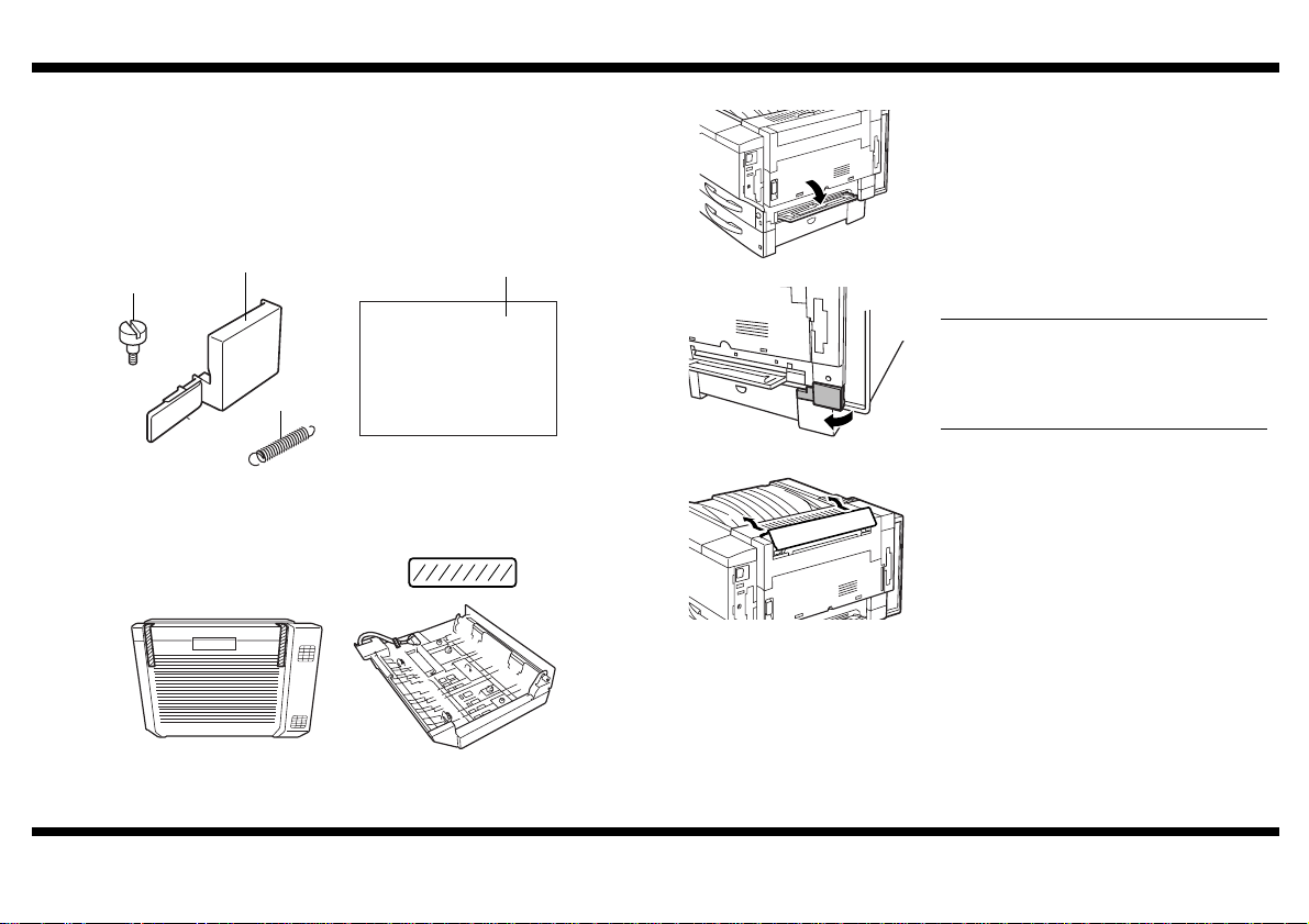
1. Remove the duplex unit from its box, and then check that the following accessories
are also enclosed.
(1) Flat-head screws. . . . . . . . . . . . . . . . . . . . . . . . . . . . . . . . . . . . . . . . . . . . . 2
(2) Wiring cover . . . . . . . . . . . . . . . . . . . . . . . . . . . . . . . . . . . . . . . . . . . . . . . . 1
(3) Spring . . . . . . . . . . . . . . . . . . . . . . . . . . . . . . . . . . . . . . . . . . . . . . . . . . . . . 1
(4) Setup Instructions (this manual) . . . . . . . . . . . . . . . . . . . . . . . . . . . . . . . . . 1
■
Preparing to Install the Duplex Unit
1. Turn off the copier, unplug the power cord
and the interface cable from the copier.
Then, open the manual bypass tray.
(1)
(2)
(3)
2. Remove all packing material from the duplex unit.
4657-7744-12
(4)
C4657U001AA
C4657U016AA
2. Remove the wiring cover from the copier.
NOTE
The wiring cover removed from the copier
will not be installed again; however , it should
be stored in a safe place in case it will be
needed later for transporting the copier.
3. Push up on the upper-right cover as shown
in the illustration, and then remove the cover.
Tape
– 1 –
Page 3

C4657U026AA
C4657U024AA
NEXT
Duplex Unit
4. Grasp the upper right-side door as shown,
and then carefully open the door completely
while making sure to support it.
NOTE
Be sure to suppor t the door while carefully
opening it; otherwise, it may be damaged.
5. Remove the two screws securing the paper
output cover, and then remove the cover.
7. Re-install the paper output cover.
4657-7744-12
C4657U022AA
C4657U023AA
6. Remove the spring indicated in the illustration, and then replace it with the enclosed
spring.
NOTE
• Be sure to i nstall the spri ng so that it is
oriented as shown in the illustration.
• The area around the fusing unit is
extremely hot. Touching any part other
than those specified may result in burns.
C4657U020AB
8. Using the two screws, secure the paper output cover.
9. Close the upper right-side door.
– 2 –
Page 4

Duplex Unit
C4657U009AA
C4657U010AA
C4657U017AA
C4657U011AA
NEXT
■
Installing the D uplex Unit
1. Align the two tabs on the duplex unit with the two holes in the copier, and then install
the duplex unit.
C4657U005AAC4657U013AA
NOTE
While suppor ting the duplex unit, ope n the
door on the right side of the copier, and
make sure that the tabs are sec ured withi n
the holes in the copier door.
3. Plug the two connectors from the duplex unit
into the connectors on the copier.
C4657U006AA
2. Open the duplex unit, and then secure the duplex unit to the copier with the enclosed
flat-head screws.
Firmly tighten the screws with a coin or screwdriver.
NOTE
Keep the duplex unit supported until it is secured with the screws.
C4657U008AAC4657U007AA
4657-7744-12
4. Secure the cable of the duplex unit with the
cable holder as shown.
5. Install the enclosed wiring cover.
– 3 –
Page 5

Duplex Unit
C4657P002CA
C4004O 068CA
C4657U014AA
a
NEXT
■
Checking and Adjusting the Paper Reference Position
NOTE
Perf orm the procedure below after adjusting the paper reference positions for the paper
feed unit and the large-capacity cabinet.
1. Display the Tech. Rep. Mode screen.
(For details about displaying the Tech. Rep.
Mode screen, refer to the Service Manual.)
C4658P001CA
2. Touch “Machine Adjust”.
5. Touch “1st.”.
6. Press the Start key.
A test page is printed.
4657-7744-12
C4659P004CA
C4657P001CA
3. Touch “PRT Area”.
4. Touch “Dup. Left Margin”.
7. Measure the width of loss for the test pattern
printed on the back of the test page.
NOTE
Do not measure from the back of the test
pattern.
Standard width (a): 3.0 mm ± 1.0 mm
If the measured width of loss does not meet
its standard width, touch and in the
lower-right corner of the screen to adjust the
width.
Print another test page and check the printed
image.
– 4 –
Page 6

Duplex Unit
RETURN
8. Adjust the paper reference positions for the
2nd, 3rd and 4th drawers in the same way
(by repeating steps 5 through 7).
NOTE
The 4th drawer is only available if two
optional paper feed units are installed.
4657-7744-12
– 5 –
 Loading...