


Doc. CV / CR 3.3
January 2018
User & Installation Manual
intarblock
MCV-N, MCV-C
BCV-N, BCV-C
MCV-I, BCV-I
intartop
MCR-N, MCR-C
BCR-N, BCR-C

2
I. Quick Start Guide
Congratulations! You have acquired a high quality cooling unit. Your INTARBLOCK and INTARTOP
units are specially designed to equip positive temperatura cold romos in the range from -5ºC (23ºF) to
+10 ºC (50ºF), and from -15ºC (5ºF) to -25ºC (13ºF), depending on the range.
Once installed, your INTARSPLIT unit can be fully operated from the remote keyboard. The control
keyboard has the following functions and characteristics.
The unit has four operation modes:
Refrigeration mode.- this is the normal operation mode. The display shows the room temperature
and by pressing the set key the target temperature is shown. During the operation the electronic
control keeps a record of the maximum and minimum room temperature ever measured, which can be
consulted at any time.
Defrost mode.- the time on time your unit will switch to the defrost mode to eliminate the frost that has
formed on the evaporator. You can also force a defrost cycle by pressing the corresponding key.
Fast cooling mode.- If you like you can activate this operation mode during the start-up of the cold
room. The unit will run continuously for the preset time in parameter “CCt”, even beyond the target
temperature.
Energy saving mode.- If you like you can activate or deactivate this operation mode to save energy
during the night or when the room will stay closed for a long time. By activating this function the target
temperature is increased according to preset value in parameter “HES”.
Press for 3 seconds
to
activate the energy
saving function
Press to switch on
and off the room light
Press for 3 seconds
to force a defrost
cycle
Press to visualise
minimum temperature
record
Press to visualise the
target temperature,
which can be modified
by pressing or
Press to visualise
maximum temperature
record
Press to turn on and
off the unit
DIGITAL DISPLAY
It shows the room
temperature.
By pressing the set key
it will show the target
temperature.
Operation LEDs

intarblock | intartop
3
Basic keyboard functions.-
To switch ON and OFF the instrument.
To switch ON and OFF the room light.
To visualise maximum room temperature record
In programming mode it increases the displayed value or explores the parameter list.
by pressing the key for 3 seconds the fast cooling cycle starts.
To visualise minimum room temperature record
In programming mode it decreases the displayed value or explores the parameter list.
To display and modify target set point; in programming mode it selects a parameter or
confirm an operation.
By holding it pressed for 3s when max or min temperature is displayed it will be erased.
By holding it pressed for 3s a manual defrost cycle starts.
By holding it pressed for 3s Energy Saving function is activated or deactivated.
II. CONTENTS
1. DESCRIPTION ........................................................................................................................ 4
2. IDENTIFICATION .................................................................................................................... 4
3. OPERATION............................................................................................................................ 5
4. OPERATION LIMITS ............................................................................................................... 6
5. COMPOSITION ....................................................................................................................... 7
6. TESTS ..................................................................................................................................... 8
7. SAFETY DEVICES .................................................................................................................. 8
8. MCV SERIES TECHNICAL FEATURES ................................................................................ 9
9. BCV SERIES TECHNICAL FEATURES ............................................................................... 11
10. MCR SERIES TECHNICAL FEATURES .............................................................................. 12
11. BCR SERIES TECHNICAL FEATURES ............................................................................... 14
12. COOLING CAPACITY R404A ............................................................................................... 15
13. COOLING CAPACITY R134a ............................................................................................... 15
14. DIMENSIONS ........................................................................................................................ 18
15. ELECTRICAL CONNECTIONS ............................................................................................. 20
16. EMERGENCY SYSTEM........................................................................................................ 21
17. SOUND PRESSURE LEVEL ................................................................................................ 21
18. TRANSPORT......................................................................................................................... 21
19. DATA PLATE ......................................................................................................................... 22
20. SAFETY RECOMMENDATIONS .......................................................................................... 22
21. INSTALLATION AND MOUNTING........................................................................................ 23
22. START-UP ............................................................................................................................. 27
23. MAINTENANCE .................................................................................................................... 28
24. REFRIGERANT LOAD .......................................................................................................... 29
25. DISPOSAL MANAGEMENT .................................................................................................. 30
26. CONTROL ............................................................................................................................. 30
27. PARAMETER LIST ................................................................................................................ 33
28. FAULT ANALYSIS ................................................................................................................. 37
29. GUARANTEE ........................................................................................................................ 40

4
1. DESCRIPTION
INTARBLOCK and INTARTOP units are monoblock refrigeration units in vertical and roof construction,
fullly tested and adjusted in Factory. They are assembled on a prelacquered galvanised steel shell and
have been designed for indoor installation, with easily removable panels to give access to fans,
refrigerant circuit, and electric board.
INTARBLOCK:
MCV Series are designed for positive temperature refrigeration applications from -5ºC (23ºF) to +10ºC
(50ºF) and consist of 12 models to cover a cooling capacity range from 0.5 kW to 3 kW
BCV Series are designed for positive temperature refrigeration applications from -15ºC (5ºF) to -25ºC
(13ºF) and consist of 9 models to cover a cooling capacity range from 0.4 kW to 2,5 kW
INTARTOP:
MCV Series are designed for positive temperature refrigeration applications from -5ºC (23ºF) to +10ºC
(50ºF) and consist of 10 models to cover a cooling capacity range from 0.5 kW to 2,5 Kw
BCR Series are designed for positive temperature refrigeration applications from -15ºC (5ºF) to -25ºC
(13ºF) and consist of 6 models to cover a cooling capacity range from 0.4 kW to 1,7 kW
- NF version – featuring axial condensation fan,
- CF version – featuring centrifugal condensation fan for ducted air extraction.
2. IDENTIFICATION
INTARBLOCK and INTARTOP series are identified according to the following nomenclature on the
product data plate.
M C V - N F - 1 024
Compressor capacity
Construction size
R-404A refrigerant
Vertical construction
Compact construction
(N) Standard (C) Centrifugal
Medium temperature

intarblock | intartop
5
3. OPERATION
INTARBLOCK and INTARTOP are refrigeration machines operating under a vapour compression
cycle.
Refrigeration cycle
The refrigeration cycle uses a phase change refrigerant fluid in a closed circuit, with the following four
steps:
Expansion: refrigerant expansion takes place in the capillary tube between high and low pressure
sections. During the expansion, liquid refrigerant cools down to the evaporating temperature.
Evaporation: In the evaporator the refrigerant evaporates under constant temperature and pressure
absorbing heat from the cold room. Once the refrigerant vapour has been fully evaporated, it is slightly
overheated beyond the evaporation temperature.
Compression: The resultant refrigerant vapour is suctioned from the evaporator by the compressor
through the suction line. The compressor compresses the refrigerant vapour up to high pressure and
temperature.
Condensation: the hot high pressure gas is desuperheated and condensed, at a constant pressure
and temperature, in the el condenser by exhausting the latent evaporation to the outer ambient. Once
the refrigerant has been fully condensed, the liquid refrigerant is overcooled beyond the condensing
temperature.
High pressure liquid refrigerant is then driven to the capillary tube, and therefore closing the circuit.
Defrost cycle
Because of the evaporator temperature can be below 0ºC (32ºF), frost is likely to deposit on the
evaporator surface through the condensation of the water vapour contained in the air. To prevent the
air flow from being obstructed with the consequently loss of performance, the instrument switches
automatically to the defrost operation mode every given period of time.
During the defrost cycle, by opening the solenoid valve, part of the hot gas from the compressor
discharge is injected into the evaporator. The evaporator temperature is rapidly increased in order to
melt the frost on it while the inside fan is off.
The defrost water is collected in the drain tray and conducted to the drain bucket. This drain bucket
contains a hot gas coil to progressively evaporate the drain water to the outer ambient.

6
4. OPERATION LIMITS
INTARBLOCK and INTARTOP units are designed for continuous operation within the following
temperature limits:
Cold Room Temperature
Ambient Temperature
Max
Min Max
Min
MCV +10 ºC (50ºF) -5 ºC (23ºF) +45 ºC (113ºF) +15 ºC (59ºF)
BCV -15 ºC (5ºF) -25 ºC (-13ºF) +45 ºC (113ºF) +15 ºC (59ºF)
MCR 10 ºC (50ºF) -5 ºC (23ºF) +45 ºC (113ºF) +15 ºC (59ºF)
BCR -15 ºC (5ºF) -25 ºC (-13ºF) +45 ºC (113ºF) +15 ºC (59ºF)
The unit should work beyond these limits only for short periods of time or during the start-up.
AP
BP
SOLENOID
VALVE
COMPRESSOR
DRAIN BUCKET
EVAPORATOR
CONDENSER
DRAIN TRAYFILTER
AP
BP
PRESSURE
REGULATOR
(only BCV/BCR)
CAPILLARY TUBE /
THERMOSTATIC
EXPANSION VALVE

intarblock | intartop
7
5. COMPOSITION
MCV / BCV units are built on a self-contained construction. The components are assembled on a steel
structure and covered with a prelacquered galvanised steel shell. It consists of:
Refrigerant circuit
§ Hermetic reciprocating compressor with internal protection, assembled on silentblocs
§ R404-A or R134a refrigerant load.
§ HP and LP pressure switches.
§ HP and LP load nipples.
§ Thermostatic expansion valve (capillary tube in medium temperature models with power lower
than 1,5 HP (R404A) and 1 HP (R134a).
§ Antiacid dehydrating filter.
§ Evaporation coil in copper tubes and aluminium fins with stainless steel drain tray.
§ Condensation coil in copper tubes and aluminium fins.
§ Solenoid valve for the hot gas bypass.
§ Water drain bucket including hot gas coil for the automatic evaporation of drain water.
Air circuits
N/I version:
§ Direct driven axial fans with single phase motor. Dynamically equilibrated blades with protection
grill.
C version:
§ Direct driven centrifugal fans with single phase motor. Dynamically equilibrated rotor.
Electric board
§ Circuit breaker protection
§ Electric control XW270K with the following elements and features:
- transformer 230 VAC / 12 VCC,
- microprocessor,
- alarm relay,
- compressor relay,
- defrost relay,
- evaporator fan relay,
- cold room light relay,
- condenser fan relay,
- door switch digital input
- H/LP pressure switch input
- inside temperature NTC probe
- outside temperature NTC probe
- defrost NTC probe
- RS485 connection,
- programming key connection,

8
- V820 keyboard.
§ Compressor permanent condenser in single phase units.
§ Compressor start relay and condenser in single phase units.
§ Ground connection for compressor and motorfans.
§ Cold room light.
§ Door microswitch connection.
§ Door microswitch (as an option).
§ Door heating cable (only for BCV and BCR models).
§ Crankcase heater (as an option).
§ Draining pipe heating cable (only for BCV y BCR models).
6. TESTS
Every INTARBLOCK and INTARTOP units have been previously checked and tested in factory
according to the following test protocol:
§ Helium leak-proof test. A leak-proof certificate is supplied upon request.
§ Refrigerant load.
§ Operation test for refrigeration and defrost modes under nominal operating conditions.
§ Safety devices checking
7. SAFETY DEVICES
INTARBLOCK and INTARBLOCK units feature the following safety devices:
§ HP and LP pressure limit switches to protect the unit against unusual pressure levels.
§ Thermal switches with automatic restart in compressor and fans to protect motor wirings from
overloads.
§ Circuit breaker protection
§ Common ground connection.

intarblock | intartop
9
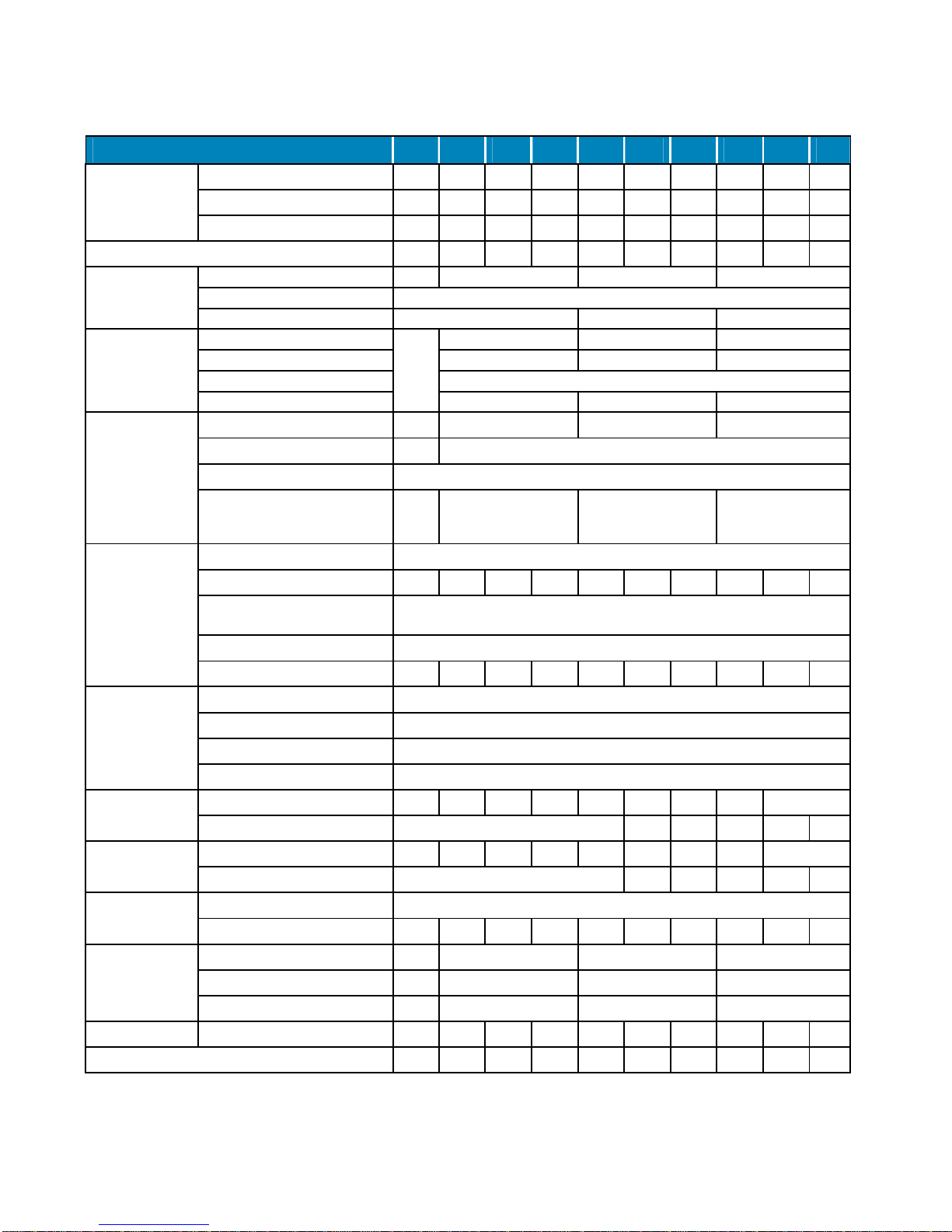
8. MCV SERIES TECHNICAL FEATURES
(1) Cooling capacity under cold room temperature of 0 ºC (32 ºF) and ambient temperature of 35 ºC (95 ºF).
(2) Total absorbed power by compressor and fans under nominal condition (axial version).
(3) As defined by RD138/2011. IF-01.
(4) Maximum absorbed current even beyond compressor operation limits (axial version).
MCV Series R404A
0008 0010 0012 1010 1012 1014 1016 1018 1024 2024 2026 2034 3034 3038
Cooling
capacity
Cooling capacity (1) (W) 610 728 808 799 930 1077 1184 1347 1468 1917 2149 2391 2690 3020
Absorbed power (2) (W) 470 570 640 649 672 804 869 1020 1175 1356 1474 1946 2070 1970
COP performance 1,30 1,28 1,27 1,23 1,38 1,34 1,36 1,32 1,25 1,41 1,46 1,23 1,30 1,53
Installed power (3) (kW) 0,53 0,73 0,86 0,75 0,82 0,98 1,10 1,38 1,68 1,68 1,89 2,63 2,63 2,35
Condenser
fan
NF version
Nominal air flow rate (m3/h)
375
575 1000 1350
Type Axial
Power (W) - r.p.m
85W @ 1300
2 x 85W @ 1300 2x70W@1300
Condenser
fan
CF version
Nominal air flow rate (m3/h)
-
575 1000 1350
Available static pressure (Pa) 45 90 120
Type Centrifugal
Power (W) 45 W 105 W 2 x 10⁵ W
Evaporator
fan
Nominal air flow rate (m3/h) 300 550 1050 1400
Range (m) 3 4
Type Axial
Power (W) - r.p.m 47W @ 2500 62W @ 2600 2 x 62W @ 2600 2x70W@2600
Compressor
Type Hermetic reciprocating
Swept volume (m3/h) 1,16 1,54 1,79 1,64 1,96 2,32 2,65 3,18 4,21 4,21 4,52 6,01 6,01 6,60
Nominal discharge pressure
(bar rel.)
20
Nominal suction pressure (bar
rel.)
3,40
Nominal power (CV) 1/3 3/8 1/2 3/8 1/2 1/2 5/8 3/4 1 1 1 1/4 1 1/2 1 1/2 1 3/4
High
pressure
switch
Type ACB
Brand Danfoss
Model 061F8175
Cut out (bar rel.) 28
Max.
absorbed
intensity
(A)(4)
230 V / I ph / 50 Hz 4,5 5,9 6,7 5,1 6,1 6,7 7,6 8,9 11,1 11,9 12,3 16,9 17,1 N/D
400 V / III ph / 50 Hz Not available 5,7 6,5 6,7 7,9
Starting-up
intensity (A)
230 V / I ph / 50 Hz
16,3 18,8 20,2 16,9 17,9 20,9 23,5 30,9 34,4 35,2 33,7 46,7 46,9 N/D
400 V / III ph / 50 Hz Not available 19,7 24,7 24,9 17,9
Refrigerant
Type R-404A / Group L1 / GWP-100: 3922
Load (kg) 0,50 0,50 0,56 0,70 0,70 0,70 0,78 0,76 0,76 1,00 0,98 1,10 1,66 1,50
Dimensions
Length (mm)
556 854 854 879
Wide (mm) 420 400 620 735
Height (mm) 683 880 920 920
Weight (kg) 35 37 38 59 60 60 69 70 70 88 89 89 117 114
Sound pressure level db(A) 30 30 30 31 31 32 34 35 35 36 38 40 39 40

10
(1) Cooling capacity under cold room temperature of 0 ºC (32 ºF) and ambient temperature of 35 ºC (95 ºF).
(2) Total absorbed power by compressor and fans under nominal condition (axial version).
(3) As defined by RD138/2011. IF-01.
(4) Maximum absorbed current even beyond compressor operation limits (axial version).
MCV series R134a
0010 0015
1015 1026 1033 2033 2053 3053
3074
3108
Cooling capacity
Cooling capacity (1) (W) 610 794 972
1281 1454 1790 2153 2489
3239
3927
Absorbed power (2) (W)
430 530 570 810 920
1090 1460 1510
1890
2480
COP performance 1,42 1,50 1,71 1,58 1,58 1,64 1,47 1,65 1,71 1,58
Installed power (3) (kW) 0,59 0,83 0,83 1,22 1,44 1,44 2,2 2,2 2,9 4,4
Condenser fan
NY version
Nominal air flow rate (m3/h) 375 575 950 1150
Type
Axial
Power (W) - r.p.m 85 W @ 1300
1300
2x 70 W @ 1300
Condenser fan
CY version
Nominal air flow rate (m3/h) 375 575 950 1150
Available static pressure (Pa) 120
Type Centrifugal
Power (W) 180 W 220 W 2x 200W 2x 200W
Evaporator fan
Nominal air flow rate (m3/h) 300 500 950 1300
Range (m) 3 4
Type Axial
Power (W) - r.p.m 47W @ 2500 62W @ 2600
2x 62W @
2600
2x 70W @ 2600
Compressor
Type Hermetic reciprocating
Swept volume (m3/h) 2,08 3,18 3,18 4,51 5,69 5,69 9,26 9,26 12,92
Nominal discharge pressure (bar rel.) 10
Nominal suction pressure (bar rel.) 1
Nominal power (CV) 3/8 1/2 1/2 3/4 1 1
1 1/2 1 1/2
2 5
High pressure switch
Type ACB
Brand Danfoss
Model 061F6147
Cut out (bar rel.) 20
Max. absorbed
intensity (A)(4)
230 V / I ph / 50 Hz 5,9 6,9 7,0 10,7 10,9
11,17
13,77
14,19
19,74 -
400 V / III ph / 50 Hz Not available 18,5
Starting-up intensity
(A)
230 V / I ph / 50 Hz 13,2 20,7 20,7 27,0 30,0 30,0 46,0 46,0 55,0 400 V / III ph / 50 Hz Not available 65
Refrigerant
Type R-134a / Group A1 / GWP-100: 1430
Load (kg) 0,56 0,62 0,64 0,64 0,70 0,90 0,90 1,30 1,20 1,40
Dimensions
Length (mm) 306+250 340+514 340+514 365+514
Wide (mm) 420 400 620 735
Height (mm) 683 880 920 940
Weight (kg) 36 38 60 69 70 88 89 117 114 116
Sound pressure level db(A) 28 29 29 34 34 35 39 38 41 43
intarblock | intartop
11
9. BCV SERIES TECHNICAL FEATURES
(1)
Cooling capacity under cold room temperature of -20 ºC (-4 ºF) and ambient temperature of 35 ºC (95 ºF).
(2) Total absorbed power by compressor and fans under nominal condition (axial version).
(3) As defined by RD138/2011. IF-01.
(4) Maximum absorbed current even beyond compressor operation limits (axial version).
BCV Series R404A
0018
1018 1026 1034 2034 2054 2074 3074 3086 3096
Cooling capacity
Cooling capacity (1) (W)
479 489 720 866 1048 1349 1633 1930 2270 2460
Absorbed power (2) (W) 620 688 914 1136 1187 1685 2014 2380 2320 2640
COP performance 0,77 0,73 0,79 0,76 0,88 0,80 0,81 0,81 0,98 0,93
Installed power (3) (kW) 0,87 0,88 1,29 1,76 1,76 2,60 3,39 3,39 3,46 4,31
Condenser fan
NF version
Nominal air flow rate (m3/h)
375 575 1000 1350
Type Axial
Power (W) - r.p.m 85W @ 1300 2 x 85W @ 1300 2 x 70W @ 1300
Condenser fan
CF version
Nominal air flow rate (m3/h)
-
575 1000 1350
Available static pressure (Pa)
45 90 120
Type Centrifugal
Power (W) 45 W 105 W 2 x 10⁵ W
Evaporator fan
Nominal air flow rate (m3/h) 300 550 1050 1400
Range (m) 3 4
Type Axial
Power (W) - r.p.m
47W
@
2500
62W @ 2600 2 x 62W @ 2600 2 x 70W @ 2600
Compressor
Type Hermetic reciprocating
Swept volume (m3/h) 3,18 3,18 4,57 6,01 6,01 9,25 12,91 12,91 11,80 16,70
Nominal discharge pressure (bar
rel.)
20
Nominal suction pressure (bar rel.) 1,30
Nominal power (CV) 5/8 5/8 3/4 1 1/4 1 1/4 1 3/4 2 1/2 2 1/2 3 3 1/2
High pressure
switch
Type ACB
Brand Danfoss
Model 061F8175
Cut out (bar rel.) 28
Max. absorbed
intensity (A)(4)
230 V / I ph / 50 Hz 4,8 7,2 8,4 10,9 11,7 17,7 25,7 25,9 No disponible
400 V / III ph / 50 Hz Not available 6,5 7,2 7,4 10,3 12,0
Starting-up
intensity (A)
230 V / I ph / 50 Hz 21,9 21,9 29,9 40,9 41,7 69,7 82,7 82,9 No disponible
400 V / III ph / 50 Hz Not available 24,7 29,7 29,9 26,9 33,9
Refrigerant
Type R-404A / Group L1 / GWP-100: 3922
Load (kg) 0,60 0,70 0,70 0,60 1,15 1,05 1,10 1,50 1,50 1,20
Dimensions
Length (mm) 556 854 854 879
Wide (mm) 420 400 620 735
Height (mm) 683 880 920 920
Weight (kg) 38 59 60 60 89 102 102 131 117 129
Sound pressure level db(A) 33 38 38 40 41 42 43 43 40 50

12
10. MCR SERIES TECHNICAL FEATURES
(1) Cooling capacity under cold room temperature of 0 ºC (32 ºF) and ambient temperature of 35 ºC (95 ºF).
(2) Total absorbed power by compressor and fans under nominal condition (axial version).
(3) As defined by RD138/2011. IF-01.
(4) Maximum absorbed current even beyond compressor operation limits (axial version).
MCR Series R404A
0008 0010 0012
1010 1012 1014 1016 1018 1024 2024 2026 2034
Cooling
capacity
Cooling capacity (1) (W) 612 738 838 799 930 1087 1194 1378 1478 2020 2223 2527
Absorbed power (2) (W) 470 580 650 652 672 811 880 1038 1201 1319 1425 1903
COP performance 1,30 1,27 1,29 1,23 1,38 1,34 1,36 1,33 1,23 1,53 1,56 1,33
Installed power (3) (kW) 0,53 0,73 0,86 0,75 0,82 0,98 1,10 1,38 1,68 1,68 1,89 2,63
Condenser
fan
NF version
Nominal air flow rate (m3/h) 375 575 1150
Type Axial
Power (W) - r.p.m 85 W @ 1300 rpm 120W @ 1300 rpm
Condenser
fan
CF version
Nominal air flow rate (m3/h)
-
575 1150
Available static pressure (Pa) 45
Type Centrifugal
Power (W) 45 W @ 1300 rpm 105 W @ 1300 rpm
Evaporator
fan
Nominal air flow rate (m3/h) 300 600 1150
Range (m) 3 4
Type Axial
Power (W) - r.p.m 47@ 2500 rpm 62W @ 2600 rpm
2x 62W @ 2600
rpm
Compressor
Type Hermetic reciprocating
Swept volume (m3/h) 1,16 1,54 1,79 1,64 1,96 2,32 2,65 3,18 4,21 4,21 4,52 6,01
Nominal discharge pressure (bar
rel.)
20
Nominal suction pressure (bar
rel.)
3,40
Nominal power (CV) 1/3 3/8 1/2 3/8 1/2 1/2 5/8 3/4 1 1 1 1/4 1 1/2
High pressure
switch
Type ACB
Brand Danfoss
Model 061F8175
Cut out (bar rel.) 28
Max.
Absorbed
intensity(4)(A)
230 V / I ph / 50 Hz 4,5 5,9 6,7 5,1 6,1 6,7 7,6 8,9 11,1 11,6 12,0 16,6
400 V / III ph /50 Hz Not available 5,4 6,2
Starting up
intensity (A)
230 V / I ph / 50 Hz 16,3 18,8 20,2 16,9 17,9 20,9 23,5 30,9 34,4 34,9 33,4 46,4
400 V / III ph /50 Hz
Not available 19,4 24,4
Refrigerant
Type R-404A / Group L1 / GWP-100: 3922
Load (kg) 0,50 0,50 0,50 0,80 0,70 0,80 0,83 0,76 0,86 1,10 1,05 1,10
Dimensions
Length (mm) 790 850 850
Wide (mm)
600 665 835
Height (mm) 480 385+189 468+189
Weight (kg) 62 64 65 73 73 73 82 83 83 98 99 99
Sound pressure level db(A) 30 30 30 32 32 32 34 35 35 36 38 40

intarblock | intartop
13
(1) Cooling capacity under cold room temperature of 0 ºC (32 ºF) and ambient temperature of 35 ºC (95 ºF).
(2) Total absorbed power by compressor and fans under nominal condition (axial version).
(3) As defined by RD138/2011. IF-01.
(4) Maximum absorbed current even beyond compressor operation limits (axial version).
MRC series R134a 0010 0015 1015 1026 1033 2033 2053 2074
Cooling capacity
Cooling capacity (1) (W) 605 788 999 1265 1502 1911 2352 2940
Absorbed power (2) (W) 430 530 580 930 1050 1210 1670 1830
COP performance 1,41 1,48 1,72 1,36 1,43 1,58 1,41 1,61
Installed power (3) (kW) 0,83 0,83 1,22 1,44 1,44 2,2 2,9
Condenser fan
NF version
Nominal air flow rate (m3/h) 375 575 1000
Type Axial
Power (W) - r.p.m 85 W @ 1300 120 W @ 1300
Condenser fan
CF version
Nominal air flow rate (m3/h) 375 575 1000
Available static pressure (Pa) 120
Type Centrifugal
Power (W) 180 W 220 W 2x 200 W
Evaporator fan
Nominal air flow rate (m3/h) 300 600 1150
Range (m) 4
Type Axial
Power (W) - r.p.m
47W @ 2500
62W @ 2600 2x 62W @ 2600
Compressor
Type Hermetic reciprocating
Swept volume (m3/h) 2,08 3,18 3,18 4,51 5,69 5,69 9,26 12,92
Nominal discharge pressure (bar rel.) 10
Nominal suction pressure (bar rel.)
1
Nominal power (CV) 3/8 1/2 1/2 3/4 1 1 1 1/2 2
High pressure switch
Type ACB
Brand Danfoss
Model 061F6147
Cut out (bar rel.) 20
Max. Absorbed intensity(4)(A)
230 V / I ph / 50 Hz 5,94 6,94 7,00 10,70 10,90 11,17 13,7 11,77
400 V / III ph /50 Hz Not available
Starting up intensity (A)
230 V / I ph / 50 Hz 16 22 22 29 30 30 46 55
400 V / III ph /50 Hz Not available
Refrigerant
Type R-134a / Grupo A1 / PCA-100: 1430
Load (kg) 0,46 0,50 0,70 0,70 0,60 1,00 1,00 1,10
Dimensions
Length (mm) 790 850 850
Wide (mm) 600 665 835
Height (mm) 330+100 385+135 469+135
Weight (kg) 62 65 73 82 83 98 99 110
Sound pressure level db(A) 30 30 28 34 34 35 39 41

14
11. BCR SERIES TECHNICAL FEATURES
(1) Cooling capacity under cold room temperature of 0 ºC (32 ºF) and ambient temperature of 35 ºC (95 ºF).
(2) Total absorbed power by compressor and fans under nominal conditions.
(3) As defined by RD138/2011. IF-01.
(4) Maximum absorbed current even beyond compressor operation limits (axial version)
BCR Series R404A 0008 1018 1026 1034 2034 2054 2074
Cooling capacity
Cooling capacity (1) (W) 515 502 734 876 1102 1443 1689
Absorbed power (2) (W) 630 671 928 1160 1297 1830 2147
COP performance
0,81 0,75 0,79 0,76 0,85 0,79 0,79
Installed power (3) (kW) 0,87 0,88 1,29 1,76 1,76 2,60 3,39
Condenser fan
NF version
Nominal air flow rate (m3/h) 375 575 1150
Type Axial
Power (W) - r.p.m
85 W @ 1300 rpm 120 W @ 1300 rpm
Condenser fan
CF version
Nominal air flow rate (m3/h)
-
575 1150
Available static pressure (Pa) 45
Type Centrifugal
Power (W) 45 W @ 1300 rpm 105 W @ 1300 rpm
Evaporator fan
Nominal air flow rate (m3/h) 300 600 1150
Range (m) 3 4
Type Axial
Power (W) - r.p.m
47 W @
2500rpm
62 W @ 2600 rpm 2 x 62 W @ 2600 rpm
Compressor
Type Hermetic reciprocating
Swept volume (m3/h) 3,18 3,18 4,57 6,01 6,01 9,25 12,91
Nominal discharge pressure (bar
rel.)
20
Nominal suction pressure (bar rel.) 1,30
Nominal power (CV) 5/8 5/8 3/4 1 1/4 1 1/4 1 3/4 2 1/2
High pressure
switch
Type ACB
Brand Danfoss
Model 061F8175
Cut out (bar rel.) 28
Max. absorbed
intensity (A)
230 V / I ph / 50 Hz 4,8 7,2 8,4 10,9 11,4 17,4 25,4
400 V / III ph / 50 Hz Not available 6,21 6,91
Starting-up
intensity (A)
230 V / I ph / 50 Hz 21,9 21,9 29,9 40,9 41,4 69,4 82,4
400 V / III ph /50 Hz Not available 24,4 29,4
Refrigerant
Type R-404A / Grupo L1 / PCA-100: 3260
Load (kg) 0,64 0,75 0,75 0,80 1,20 1,00 1,10
Dimensions
Length (mm) 790 850 850
Wide (mm) 600 665 835
Height (mm) 480 385+189 468+189
Weight (kg) 65 83 84 84 135 145 145
Sound pressure level db(A) 33 38 38 40 41 42 43

intarblock | intartop
15
12. COOLING CAPACITY R-404A
§ MCV series
Capacity (W)
Cold room temperature
-5 ºC 0 ºC +5 ºC +10 ºC
MCV series
Cooling
capacity
(W)
Absorbed
power (W)
Cooling
capacity
(W)
Absorbed
power (W)
Cooling
capacity
(W)
Absorbed
power (W)
Cooling
capacity
(W)
Absorbed
power (W)
Ambient Temp: 35 ºC
0008
502 446 610 470 738 506 860 534
0010
604 533 728 570 871 624 1012 666
0012
568 619 808 676 961 706 1118 759
1010
630 613 801 649 966 683 1157 722
1012
767 631 930 672 1118 714 1317 763
1014
893 756 1077 804 1270 858 1485 920
1016
985 800 1184 869 1386 939 1615 1018
1018
1138 940 1347 1020 1570 1104 1806 1200
1024
1207 1049 1468 1175 1739 1305 2039 1450
2024
1554 1245 1917 1356 2296 1464 2726 1579
2026
1795 1368 2149 1474 2526 1584 2945 1707
2034
1996 1805 2391 1946 2801 2102 3247 2282
3034
2230 1925 2690 2070 3200 2220 3730 2390
3038
2500 1830 3020 1970 3580 2110 4220 2270
§ BCV series
Capacity (W)
Cold room temperature
-25 ºC -20 ºC -15 ºC
MCV series
Cooling capacity
(W)
Absorbed power
(W)
Cooling capacity
(W)
Absorbed power
(W)
Cooling capacity
(W)
Absorbed power
(W)
Ambient Temp: 35 ºC
0018
379 565 479 620 591 694
1018
383 611 489 668 655 747
1026
548 802 720 914 877 1015
1034
668 986 866 1136 1023 1254
2034
793 1196 1048 1334 1297 1463
2054
963 1592 1349 1832 1655 2026
2074
1338 1931 1633 2161 1963 2405
3074
1430 2070 1930 2380 2320 2660
3086
1630 2000 2270 2320 2810 2560
3096
1890 2280 2460 2640 3040 2970

16
§ MCR Series
Capacity (W)
Cold room temperature
-5 ºC 0 ºC +5 ºC +10 ºC
MCR Series
Cooling
capacity
(W)
Absorbed
power (W)
Cooling
capacity
(W)
Absorbed
power (W)
C
ooling
capacity
(W)
Absorbed
power (W)
Cooling
capacity
(W)
Absorbed
power (W)
Ambient Temp.: 35 ºC
0008
508 455 612 470 720 521 851 547
0010
621 537 738 580 901 629 1055 681
0012
701 598 838 650 1012 712 1163 766
1010
630 617 801 652 966 682 1157 727
1012
767 637 930 672 1118 717 1317 772
1014
916 761 1087 811 1275 867 1479 929
1016
1005 811 1194 880 1402 953 1628 1031
1018
1161 957 1378 1038 1579 1118 1828 1211
1024
1217 1070 1478 1201 1782 1335 2062 1462
2024
1625 1201 2020 1319 2402 1409 2888 1527
2026
1849 1324 2223 1425 2646 1531 3077 1648
2034
2080 1768 2527 1903 2987 2059 3380 2190
§ BCR Series
Capacity (W)
Cold room temperature
-25 ºC -20 ºC -15 ºC
BCR Series
Cooling
capacity (W)
Absorbed power
(W)
Cooling capacity
(W)
Absorbed power
(W)
Cooling capacity
(W)
Absorbed power
(W)
Ambient Temp:
35 ºC
0018
405 570 515 630 618 700
1018
407 618 502 671 664 752
1026
565 813 734 928 908 1039
1034
699 1015 876 1160 1051 1287
2034
840 1157 1102 1297 1366 1433
2054
1116 1617 1443 1830 1733 2005
2074
1425 1932 1689 2147 2088 2416

intarblock | intartop
17
13. COOLING CAPACITY R-134a
· Serie MCV
Capacity (W)
Cold room temperature
0 ºC +5 ºC +10 ºC
MCV Series
Cooling
capacity (W)
Absorbed
power (W)
Cooling
capacity (W)
Absorbed
power (W)
Cooling
capacity (W)
Absorbed
power (W)
Ambient Temp: 35 ºC
0010
610 437 758 477 907 508
0015
794 532 961 587 1139 642
1015
972 572 1199 622 1453 672
1026
1281 812 1565 892 1859 972
1033
1454 922 1743 1012 2037 1112
2033
1790 1099 2163 1184 2573 1274
2053
2153 1464 2609 1634 3103 1809
3053
2489 1515 3103 1700 3743 1870
3074
3239 1895 3938 2145 4667 2400
3108
3927 2485 4725 2790 5539 3145
· Serie MCR
Capacity (W)
Cold room temperature
0 ºC +5 ºC +10 ºC
MCR Series
Cooling
capacity (W)
Absorbed
power (W)
Cooling
capacity (W)
Absorbed
power (W)
Cooling
capacity (W)
Absorbed
power (W)
Ambient Temp: 35 ºC
0010
605 432 751 471 902 505
0015
788 530 956 577 1134 640
1015
999 580 1231 673 1490 691
1026
1265 930 1549 884 1853 970
1033
1502 1050 1817 1067 2153 1176
2033
1911 1210 2363 1210 2846 1347
2053
2352 1670 2882 1689 3455 1855
2074
2940 1830 3560 1945 4211 2147

18
14. DIMENSIONS
CV-N-C Models
CV-I Models
Dimensions (mm) A B C D E F G H
1 series
340 330 1060 400 514 115 380 335
2 series
340 330 1100 620 514 115 600 335
3 series
365 470 1100 735 514 115 710 475
Dimensions (mm) A B C D E F G H I J K L M
Exhaust
duct
0 series
306 510 683 420 250 50 405 515 n/a Ø 150
1 series
340 330 880 400 514 122 380 335 75 41 295 13 233 Ø 150
2 series
340 330 920 620 514 122 600 335 75 36 523 13 233 Ø 150
3 series
365 470 920 735 514 122 710 475 75 41 611 22 356 2x Ø 150
PLUG-IN FRAME
DROP FRAME
Centrifugal Box
only in 0 series

intarblock | intartop
19
CR-N Models
CR-C Models
Dimensions (mm) A B C D E F G H I Exhaust duct
0 series
480 600 430 330 790 375 100 435 380 Ø 150
1 series
574 665 582 385 850 379 135 588 385 Ø 150
2 series
677 835 756 469 850 379 135 762 385 Ø 150
ROOF FRAME

20
15. ELECTRICAL CONNECTIONS
Before connecting the unit to the electrical supply, make sure that the electrical board is in good
conditions and please follow the following recommendations:
§ Consult the electrical schema supplied by manufacturer.
§ Only use electrical cables of the appropriate characteristics and capacity according to the following
table. Notice that single phase units have a three-wire supply and three phase units have a fivewire supply, being always the ground wire in green-yellow colour.
MCV - MCR 0008 0010 0012 1010 1012 1014 1016 1018 1024 2024 2026 2034 3034 3038
Power supply
220-I-50
2 x 1,5 mm² + T
2 x 2,5 mm² +
T
Power supply
400-III-50
4 x 1,5 mm² + T
Cold room light
2 x 1 mm² + T
Door
microswitch
2 x 1 mm²
Remote
controller
2 x 1 mm²
BCV - BCR 0018 1018 1026 1034 2034 2054 2074 3074 3086 3096
Power supply 220-I-50
2 x 1,5 mm² + T
2 x 2,5 mm² + T 2 x 4 mm² +
T
Power supply 400-III-50
4 x 1,5 mm² + T
Cold room light
2 x 1 mm² + T
Door microswitch
2 x 1 mm²
Remote controller
2 x 1 mm²
Power supply 220-I-50
2 x 1 mm²
§ Always install the appropriate protection device on the supply line. In case that more than one unit
is installed, always provide separate protection devices for each of the installed units.
§ Electrical wires section in power supply wiring is to be calculated according to the electrical data
provided by manufacturer in data plate, power supply wires length, wires type, etc.; always
according to electrical regalement.
§ Optionally install a door switch on the end of the supplied cable or close the end of the cable.
§ Install the room light in the supplied cable.

intarblock | intartop
21
16. EMERGENCY SYSTEM
The electronic regulation of the units involves control routines and emergency alarms for the following
causes:
§ Probe failure.
§ Too high and too low room temperature.
§ Too high or too low refrigerant pressure.
§ Too high ambient temperature
§ Electronic control failure
§ Opened door.
Once a failure an external alarm is activated, and the unit turns into emergency operation mode.
17. SOUND PRESSURE LEVEL
Sound pressure level should be observed once the unit is installed. To do so, the environment, the
type of building and the rest of the solid elements should be considered on the noise transmission. It is
recommended to deploy an expert study if necesary.
INTARBLOCK and INTARTOP units include low noise components. The following chart indicates
sound pressure levels calculated at 10 m from the source in open field distribution (directivity = 1):
18. TRANSPORT
Handle the unit with care to prevent damages during its transport. Please follow the following
instructions:
§ Always handle the unit in vertical position.
§ Never pile up the units during transport.
§ Never pile up the units during storage.
§ Use a forklift or a pallet jack to handle the unit.
§ Keep the unit on its pallet until its final destination.
Packaging dimensions (mm) L W H Weight
CV series 0 610 460 823 44 Kg
CV series 1 905 440 1065 76 Kg
CV series 2 905 660 1105 108 Kg
CV series 3 940 795 1105 137 Kg
CR series 0 870 660 655 77 Kg
CR series 1 920 820 700 100 Kg
CR series 2 920 985 780 162 Kg
A
L
H
A
L
H

22
19. DATA PLATE
All All units are identified with the following data plate. In all communications with the manufacturer
please indicate the serial number.
20. SAFETY RECOMMENDATIONS
The start-up of the unit and its reparation must be carried out by qualified personnel.
To minimise the risk of accidents during the installation, start up or maintenance tasks, below
instructions must be followed.
It is mandatory to observe the recommendations and instructions as shown in manufacturer manuals,
plates and specific instructions. It is also mandatory to observe law and regulations.
Before operating on the unit, verify that the general supply is disconnected to avoid
electrical shocks.
Refrigerant leaks may cause:
§ Suffocation due to oxygen displacement in the atmosphere, narcotic effect or heart
arrhythmia.
Ensure that the working area is properly ventilated.
§ Eye irritations or burns may be caused if refrigerant comes into contact with the skin.
Use a safety mask and a pair of gloves. Avoid any contact between the refrigerant and
the skin and mind any sharp end of the unit.

intarblock | intartop
23
In case of accident due to refrigerant inhalation follow the following instructions:
§ Move the victim where it could breathe fresh air. The victim should lay on its back or its shoulder.
§ Call emergency services if needed.
In case of eye injures due to refrigerant splatters:
§ Never rub the eyes. In case contact lenses are used, you must take them out.
§ Eyes should be kept open and washed with plenty of water.
§ The victim should be taken to an emergency medical service
In case of burn due to contact with the skin
§ Wash with plenty of running water the affected part and take out the clothes while water is applied
on.
§ Never cover the affected parts with cloth, bandages or oil.
21. INSTALLATION AND MOUNTING
The final emplacement of the unit will affect the good performance of the unit. For an optimal
performance, please follow the following recommendations:
§ During the reception of your unit, please verify that it is free from any transport damage. Otherwise
indicate the perceived damages on the receipt.
§ Install the unit in a room with good ventilation and away from heat sources.
§ Keep clean the surroundings of the unit to facilitate the air intake and exhaust, and make sure the
air does not reflow.
INTARBLOCK units are designed for wall mounting directly onto the cold room panel. To do so, cut
out the indicated frame on the wall panel, depending on the type of mounting.
§ Drop mounting (except series 0).-
1. Before assembling the cold room, cut out the corresponding frame for the unit structure and
drill the hole for the drain pipe in the specified position.
2. Remove the drain pipe from the drain tray. To do so screw out the side cover of the inner part
and release the end of the tube.
3. Place the unit before assembling the roof of the cold room.
4. Place the drain pipe through the hole in the panel. Then, replace the roof panel.

24
§ Plug in mounting.- on an existing cold room or new one:
1. Cut out the indicated frame on the wall panel.
2. Place the unit into the wall frame with the supplied isolating block.
§ Fix the unit to the wall panel by mean of 6 through screws of Ø 6 mm metric as indicated on the
drawing. For the drop mounting, two hang-in holes are available for Ø 8 mm metric.
INSULATING
PAD
RECOMMENDED
SEPARATION
1 000 mm
RECOMMENDED
SEPARATION
> 500 mm
COLD
ROOM
LIGHT
DOOR MICROSWITCH
DRAIN PIPE
RECOMMENDED
SEPARATION
1 000 mm
RECOMMENDED
SEPARATION
> 500 mm
COLD
ROOM
LIGHT
DOOR MICROSWITCH
SIDE
COVER
DOOR HEATER (Only BCV)
DOOR HEATER (Only BCV)

intarblock | intartop
25
Dimensions (mm) A B C D E F G H
CV series 0 (plug-in mounting)
400
+0 +5
117 ±1 135 ±1 n/a 511 +5
Dimensions (mm) A B C D E F G H
CV series 1 375
+0 +5
469 ±1 125 ±1 726.5
±1
34.5 +5 122 ±1 208 ±2 330 +5
CV series 2 595
+0 +5
509 ±1 235 ±1 766.5
±1
30.5 +5 222 ±1 208 ±2 330 +5
CV series 3 692
+0 +5
369 ±1 292 ±1 766.5
±1
39.5 +5 267.5
±1
356 ±2 470 +5
CCØ6Ø6Ø6Ø6Ø6Ø6Ø6Ø6Ø
6
52
± 1
159
± 1
C
C
H 72
+3
CCBACCØ6Ø6Ø
6
Ø8Ø
8
G
AØ2
PLUG-IN MOUNTING
DROP MOUNTING
E
2
+2
FFD
12
5
± 1

26
§ Centrifugal fan installation.- for CV-CF models.
1. Fix the unit to the cold room wall before installing the centrifugal fan.
2. Take out the side panels of the centrifugal box to access the fixing screws.
3. Screw the centrifugal box to the refrigeration unit and connect the fan electrical wiring.
4. Re install the side panels.
The INTARTOP unit series are specially designed for roof mounting. To do so, please follow below
steps:
§ Before assembling the roof of the cold room, cut out the roof frame as indicated in the plan and
dimensions chart (page 16)).
§ Once the cold room is assembled, place the unit on the roof.
§ In some operation conditions (e.g. intenstive use in wet environmment, air infiltrations, etc.), it
could be possible that the unit is not able to evaporate all condensing water. In that case, install a
draining pipe in the drain bucket to a permanent draining point.
§ Finally seal with silicon the gap between the unit and the wall panel.
To ensure good working conditions and easy access for maintenance, please keep free
the recommended separation around the unit.
Condensation air ducts (CV-C and CR-C models)
§ Units of CV-C and CR-F series feature a centrifugal condensation fan to be ducted. It is
recommended to duct the air extraction. Optionally, it is also recommended to duct the air suction
through semi-flexible ducts in aluminium or rigid ducts in PVC plastic, steel or fibreglass.
§ Failing a detailed calculation, the following chart shows the recommended dimensions according
to the duct type, for an equivalent total length of 20 m and both air intake-outtake grilles.
RECOMMENDED
SEPARATION
MINIMUM 650 mm
COLD
ROOM
LIGHT
DOOR
MICROSWITCH
RECOMMENDED
SEPARATION 5
00 mm
CONTROL PAD WIRING
DOOR
HEATER
POWER
SUPPLY

intarblock | intartop
27
CV/CR -C
Air flow
m³/h
A.s.p.
Pa
Recommended duct dimensions (mm)
Semi-flexible Rigid (PVC or steel)
CV 0 series
375 120
Ø 200 Ø 150
CV 1 series
575 120
Ø 250
< 20 m: Ø 150
>20 m: Ø 200
CV 2 series
950 120
Ø 315 Ø 200
CV 3 series
1250 120
Ø 315 Ø 250
CR 0 series
375 120
Ø 200 Ø 150
CR 1 series
575 120
Ø 250
< 20 m: Ø 150
>20 m: Ø 200
CR 2 series
1150 120
Ø 315 Ø 200
§ It is recommended a minimum length duct, avoiding placing unnecessary turns. Failing a detailed
calculation, it can be supposed that a 90º turn, with no internal radio, is equivalent to 5 m length.
§ If air intake is not ducted, an air intake adequate to the room should be planned.
§ It is not recommended the use of flexible ducts due to pressure loss, being only acceptable in case
of straight and very short stretches. If so, an aluminium semi-flexible duct as indicated diameters is
recommended.
22. START-UP
Before starting the unit,plese check that the unit is properly fixed on its supports and the electrical
connections are properly installed. If you have worked on the unit, take care not to forget tools or any
objects inside, that there is no gas leak and that assembly-connection are properly done.
Before starting up or after a stand-by periods, activating the crankage heater (when included) at
twelve hours in advance is recommended. Otherwise, the compressor must be warmed up in a
different way to ensure the refrigerant-oil separation. This operation is important, specially when
starting-ups in low ambiance temperatures.
Connect the electrical supply and switch on the unit with room door closed. The display will show the
room temperature and after the time as specified for Ods parameter the compressor will start.
Set the cold room temperature set point and wait until the cold room temperature reaches the set
point. The high temperature alarm will not be activated until the time of dAO parameter is elapsed.
Once the target temperature is reached, initialise the record of maximum and minimum temperature as
indicated in thism anual. You may check that auxiliary devices work properly:
§ Room light.- turn on and off the room light.
§ Door switch.- check that the compressor and fans stop when opening the door.
Force a manual defrost cycle to check this operation mode. make sure that the evaporation coil gets
clean and that the unit stays within the normal operating parameters without activating any safety
device.
Depending on the application you may need to modify defrost parameters, such as time
period between two consecutive defrost cycles, defrost cycle duration or termination
temperature. To do so, pay attention to the defrost cycles during normal operation.

28
Finally you can easily test the proper operation of some of the safety devices such as:
§ Open door alarm.- by leaving the door open beyond indicated in doA parameter.
§ High pressure switch or high temperature alarm.- by intentionally obstructing the air intake of
condenser.
§ Low pressure switch or Low temperature alarm.- by intentionally obstructing the air intake of
evaporator.
23. MAINTENANCE
INTARBLOCK and INTARTOP units are self-contained equipment not requiring specialised
maintenance. Nevertheless, to keep your unit in an optimal working state, we recommend to
periodically carrying out the following preventive maintenance tasks.
During the maintenance tasks, switch off the power supply and use gloves to avoid any
possible cut.
§ External cleaning.- To keep your unit free from dust and dirtiness, simply pass a wet cloth over the
cover. Do not use neither solvents nor detergents.
TORNILLOS
FIJACION
CARCASA
B
ATERIA DE
CONDENSACION
§ Condenser cleaning.- During the normal operation the dust and dirtiness will deposit on the coil
surface and will obstruct the air flow. Periodically, and depending on the surroundings, the
condenser should be cleaned. To do so, remove the external cover of the unit by removing the
side screws. Use compressed air blowing from inside or a vacuum cleaner to remove dirtiness on
the coil. Alternatively use a brush from the outer face of the coil. Do not force the fins to avoid
deformation.
§ Cleaning the evaporator (CV).- Remove any of the side covers of the evaporator block by
removing front and side screws. Blow air from outside or brush on the inner side to remove the
dirtiness on the coil.
SCREWS IN THE
COVER SIDE
SCREWS IN THE
COVER SIDE
EVAPORATION COIL
DRAIN TRAY
CONDENSER COIL
SIDE SCREWS
FIXING THE
EXTERNAL COVER

intarblock | intartop
29
§ Cleaning the evaporator (CR).- Remove the evaporator cover panel from inside cold room.
Deplace the cover to a side to access the coil. Blow or brush to clean it.
§ Drain tray.- To clean the drain tray you can use commercial detergents. In that case, make sure to
remove the detergent from the drain bucket inside the condensation block. To do so you can clean
the bucket with water. For CR units it is posible to dissasemble the evaporator box to access the
condenser coil and the drain tray. To do so, unscrew the box from the condenser and from the
lower section.
Following repair tasks should only be carried out by qualified personnel.
§ Replacement of any electrical part in the unit
§ Any modification of mechanical parts
§ Any operation on the refrigerant circuit
§ Any modification on the protection devices, control panel, control switches.
The maintenance tasks shown in this manual do not exclude any maintenance task in regulations and
laws.
24. REFRIGERANT LOAD
INTARBLOCK units are specifically designed for R404A refrigerant. The use of any other refrigerant in
the unit invalidates its guarantee.
Any operation related to the load, removal or replacement of refrigerant must always be carried out by
qualified personnel and never by the user. Please refer to technical refrigeration manuals for such
operations.
Units must always be loaded with R404A refrigerant in liquid phase through the HP nipple, in the exact
quantity indicated on the data plate.
GRILLE
CONDENSATION
COIL
EVAPORATOR
COVER PANEL
EVAPORATOR
EVAPORATOR
COIL
SIDE SCREWS
TRAY

30
25. DISPOSAL MANAGEMENT
After the installation dispose the packaging and pallet in an environmentally friendly manner and
according to your regulations. When disposing your unit or any of its parts, do it through an authorised
waste management company according to laws and regulations.
26. CONTROL
The unit is managed by a electronic board and a control keyboard with the following operating modes:
Refrigeration mode
The refrigeration operation mode is driven by a thermostatic control according to the room temperature
and a temperature target fixed by the user. Thus, when the room temperature is greater than the
temperature target, plus a pre-set differential, the compressor starts and stops when the room
temperature reaches the target temperature.
During the operation mode the display shows the room temperatura. Target temperature can be
shown by pressing the
key and can be modified by pressing
and .
To protect the compressor from successive starts, short cycle timing is inbuilt.
Fast cooling mode
The fast freezing operation mode can be activated or deactivated by pressing the key
for 3
seconds. During this operation mode the compressor works continuously for a preset period as
configured through the “CCt” parameter.
Defrost mode
After every preset period (fixed by the parameter “Idf”) the unit executes a defrost cycle. The unit is
preset on a defrost mode controlled through the inner coil temperature. In this mode, when the
evaporator coil reaches a certain temperature (as predefined value through the parameter “dtE”), or
after certain time (as predefined value through the parameter “MdF”). After a defrost cycle the unit
stays idle for the drain time (preset time through the parameter “Fdt”) to allow the evacuation of all
defrosted water.
The unit is configured to stop fans during the defrost cycle (parameter “FnC”)
After the defrost cycle and during the beginning of the normal refrigeration mode, the evaporator fan
remains stopped for the time defined by parameter “Fnd”.
Room light
Room light can be switched on and off through the key .
Keyboard
It consists of a display of 3 digits and a 7 key keyboard with LEDs to indicate operation mode and
alarms.

intarblock | intartop
31
To display and modify target set point; in programming mode it selects a parameter or confirm an operation.
By holding it pressed for 3s when max or min temperature is displayed it will be erased.
To see the max. stored temperature; in programming mode it browses the parameter codes or increases the
displayed value. By holding it pressed for 3s the fast freezing cycle is started.
To see the min stored temperature; in programming mode it browses the parameter codes or decreases the
displayed value.
By holding it pressed for 3s the defrosting is started.
Switch ON and OFF the cold room light.
By holding it pressed for 3s Energy Saving function is started or stopped.
Switch ON and OFF the auxiliary output.
Operation LEDs
LED Status
Description
Compresor LED
On The compressor is running
Flashing
Antyshort cycle safety device on. Pressure switch/es opened
(pressure
switch).
Fan LED
On The fan is running
Flashing
Programming
(flashing along with Compresor LED)
Defrosting LED
On The defrost is enable
d Flashing
Defrost is finished. Drip time in progress
Fast-cooling LED
On
The Fast Freezing cycle is enabled
Digital display
Unit On/Off
Energy saving mode key
Cold room Light switch
Defrosting key
Min temperature key
Target temperatura and
validation key
Max. Temperature and fast
-
cooling mode key
Compressor LED
Fast-cooling mode LED
Defrosting LED
Fan LED
Alarm LED

32
Keyboard functions
§ To switch off the unit.-
1. hold pressed
for 5 seconds and the display will show "OFF".
§ To show maximum temperature record.-
1. press
2. the display will show the value together with “Hi”.
3. press or wait 5 seconds to restore the normal display.
§ To show minimum temperature record.-
1. press
2. the display will show the value together with "Hi".
3. press or wait 5 seconds to restore the normal display.
§ To restart the minimum and maximum temperature record.-
1. while maximum or minimum temperature record is shown,
2. press the key set until the message “rST” is shown.
Do not forget to restart temperature records at the first start-up of the unit.
§ To show and modify target temperature.-
1. press set and the target temperature will be shown
2. the corresponding LED will begin to flash
3. press
or
to modify its value.
4. to store the new value press set or wait for 10 seconds.
§ To force a manual defrost cycle.-
1. press
for 2 seconds.
§ To access Pr1 parameter list, user parameters.-
1. press set and
simultaneously for some few seconds,
2. fan and compressor leds will flash,
3. the display will show the first parameter.
§ To access Pr2 parameter list, installer parameters.-
1. access Pr1 list,
2. select parameter “Pr2” and press set,
3. the display will show the message “PAS” followed by ”0 - -“.
4. press and
to modify the flasshing digit and confirm its value by pressing set, to enter
the password 321.
§ To modify a parameter.-
1. enter the parameter list,
2. select the parameter by pressing
or
and press set to visualise its value.

intarblock | intartop
33
3. press or
to modify its value.
4. press set to confirm then ew value and jump to the next parameter.
5. to exit the programming mode press set and or wait for 15 seconds.
§ To lock the keyboard.-
1. press and for 3 s.
2. the message “POF” will be shown and only the set point and temperature records can be
consulted.
3. To unblock the keyboard press and for 3 s.
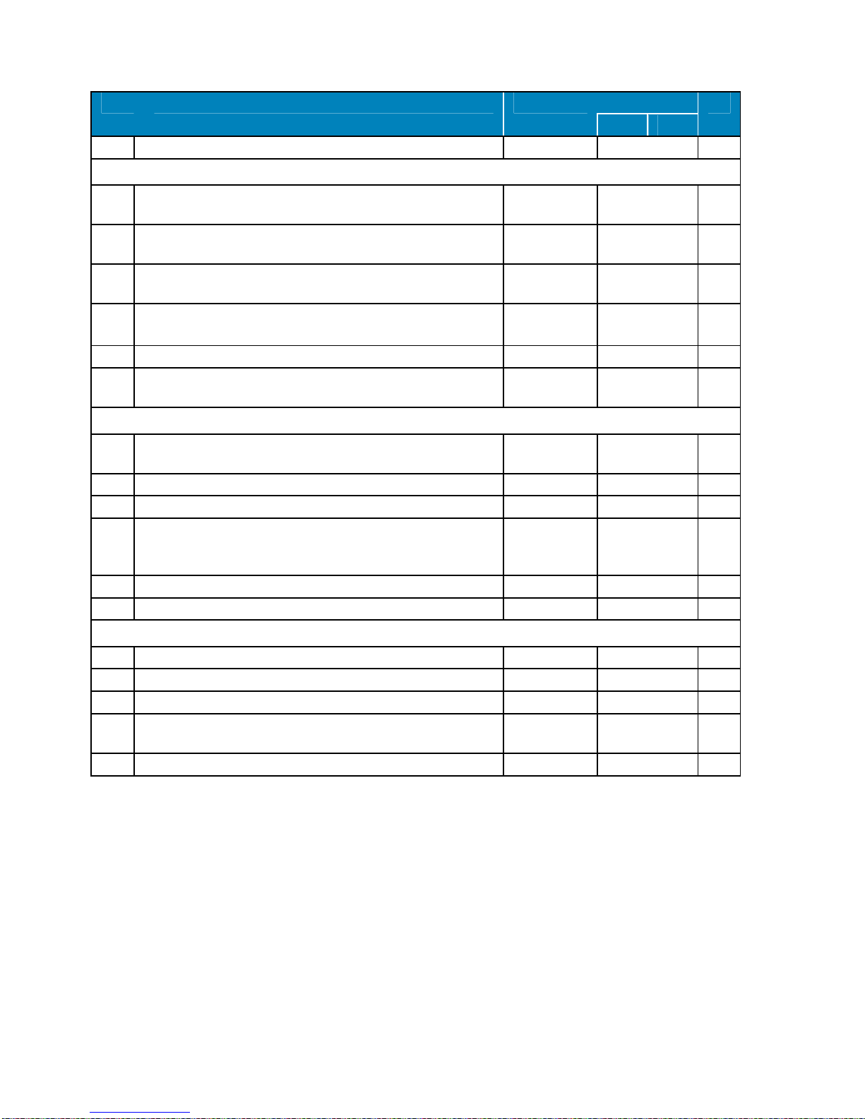
27. PARAMETER LIST
Code Description Range Default List
MT BT
REGULATION
SET
Set Point. LS ÷ US 0 ºC -20 ºC
Hy
Set Point differential. 0,1 ÷ 25,5 ºC 2,0 ºC Pr1
LS
Minimum set point
-50,0 ºC ÷
SET
-5 ºC -25 ºC Pr2
US
Maximum set point. SET ÷ 110,0 ºC 10 ºC -15 ºC Pr2
Od
S
Time in which functions excluding light are not allowed from
starting-up.
0 ÷ 255 min 1 min Pr2
AC
Antishort cycle delay 0 ÷ 30 min 2 min Pr1
CCt
Fast freezing mode time (minutes)
0 ÷ 23 h 50
min
0h
30 min
2h
30 min
Pr2
Con Time interval during which the compressor is working after probe
default
0 ÷ 255 min 15 min Pr2
CO
F
Time interval during which the compressor is stopped due to
probe default
0 ÷ 255 min 15 min Pr2
DISPLAY
CF
Temperature measurement unit. ºC - ºF ºC Pr2
rES
Resolution integer/decimal point (only if CF = ºC):
in (integer) = 1 ºC ; de (decimal) = 0,1 ºC.
in - de de Pr1
Lod
PARÁMETER NOT AVAILABLE FOR THIS MODEL P1, P2, P3, 1r2
P1 Pr2
rEd
Remote display:
P1=room probe ; P2=evap. probe ; P3=ambient probe ; 1r2=P1-
P2.
P1, P2, P3, 1r2
P1 Pr2
DEFROSTING
tdF
Defrost type. (DO NOT MODIFY).
rE=electrical heater ; rT=off time ; in=hot gas injection
rE, rT, in in Pr1
EdF
Defrosting mode: in=Standar ; Sd=SmartDefrost
in - Sd in Pr2
SdF
set point for Smart Defrost.
-30,0 ÷ 30,0
ºC
0,0 ºC Pr2
dtE
Defrosting finalization temperature.
-50,0 ÷ 110,0
ºC
20,0 ºC Pr1

34
Code Description Range Default List
MT BT
IdF
Interval between defrosting cycles. 1 ÷ 120 h 3 h Pr1
Md
F
Maximum defrosting legth.
0 ÷ 255 min 15 min Pr1
dFd
Display during defrost:
rt=real temperature ; it=last recorded temperature ; Set=set point
; dEF= “dEF” message ; dEG= “dEG”message.
rt, it,Set, dEF,
dEG
it Pr2
dAd
Delay after defrosting to display cold room temperature 0 ÷ 255 min 15 min Pr2
dSd
Defrosting start delay. 0 ÷ 99 min 0 min Pr2
Fdt
Time defrosting end to compressor starting-up (draining time). 0 ÷ 60 min 2 min 3 min Pr2
dP
O
Displayed if defrosting after starting-up.
n - y n Pr2
dAF
Defrost delay after fast freezing.
0 ÷ 23 h 50
min
2,0 h Pr2
FANS
FnC Fans operating mode: With compressor (C) / always on (O) /
during defrosting (y=yes / n=no).
C-n, C-y, O-n,
O-y
C-n Pr2
Fnd
Fans operation delay after defrosting. 0 ÷ 255 min 3 min 4 min Pr2
FSt
Fans stop temperature.
-50,0 ÷ 110,0
ºC
10 ºC 0 ºC Pr2
ALARMS
ALC
Temperature alarm configuration (ALU and ALL):
rE=relative ; Ab=absolute.
rE - Ab rE Pr2
ALU
Maximum temperature alarm
rE: -50,0 ÷ 110,0
ºC
Ab: 0,0 ÷ 50,0 ºC
5,0 ºC Pr1
ALL
Minimum temperature alarm
rE: -50,0 ÷ 110,0
ºC
Ab: 0,0 ÷ 50,0 ºC
5,0 ºC Pr1
AFH
Temperature alarm and fan differential 0,1 ÷ 25,5 ºC 2,0 ºC Pr2
ALd
Temperature alarm delay. 0 ÷ 255 min 0 min Pr2
dAO
Delay of temperature alarm after starting up.
0 ÷ 23 h 50
min
3 h 4 h Pr2
EdA
Alarm delay at the end of the defrosting 0 ÷ 255 min 30 min Pr2
dot
Delay of temperature alarm after closing the door 0 ÷ 255 min 30 min Pr2
doA
Delay of opened door alarm 0 ÷ 255 min 15 min Pr2
rrd
outputs restart after doA alarm n - y y Pr2
AL2
Condenser low temperature alarm -50,0 ÷ Au2 ºC
-40 ºC Pr2
Au2
Condenser high temperature alarm
AL2 ÷ 110,0
ºC
52 ºC Pr2
ALH
Differential of condenser low temperature alarm (AL2). 0,1 ÷ 25,5 ºC 5 ºC Pr2
AtH
Differential of condenser high temperature alarm (Au2). 0,1 ÷ 25,5 ºC 3 ºC Pr2
Ad2
Condenser temperature alarm delay 0 ÷ 255 min 0 Pr2
dA2
Condenser temperature alarm eclusion at starting up 0 ÷ 23h 50 min
0 Pr2
tbA
Alarm signal silencing by pressing a key. n - y y Pr2
intarblock | intartop
35
Code Description Range Default List
MT BT
nPS
Pressure switch activation number 0 ÷ 15 10 Pr2
ANALOGUE INPUTS
Ot
Thermostat probe calibration
-12,0 ÷ 12,0
ºC
0 Pr1
OE
Evaporator probe
-12,0 ÷ 12,0
ºC
0 Pr2
O3
Condenser probe calibration
-12,0 ÷ 12,0
ºC
0 Pr2
P2P
Evaporator probe presence:
n=no (defrosting by time) ; y=sí (desescarche por tiempo y Tª)
n - y y Pr2
P3P
Condenser probe presence: n=no ; y=yesí n - y y Pr2
HE
S
Temperature increase during the Energy Saving cycle -30,0 ÷ 30,0
ºC
2 ºC Pr2
DIGITAL INPUTS
odc When door is open, switches off the compressor (CPr), fan (Fan),
both (F_C), or non of them (no)
no, Fan, CPr,
F_C
F_C Pr2
I1P
Door micriswitch polrity. CL=Closed; OP=Opened CL - OP OP Pr2
I2P
Pressure switches polarity: CL=Closed; OP=Opened CL - OP OP Pr2
I2F
Digital input 2 configuration: PAL=Pressure switches.
EAL, bAL,
PAL, dFr,
AUS, Es, onF
PAL Pr2
did
Digital input alarm relay 0 ÷ 255 min 60 Pr2
oP2
External alarm polarity: cL=closed ; oP=Opened. cL - oP cL Pr2
OTHERS
Adr
Serial address. 1 ÷ 247 1 Pr1
rEL
Software release solo lectura 8.4 Pr2
Ptb
Dixell map code. solo lectura 2 Pr2
Prd Probe display values: thermostat “Pb1”, evaporator “Pb2” and
condenser “Pb3”.
Pb1, Pb2, Pb3 solo lectura Pr2
Pr2
Access Pr2 parameter list.
Pr1
Configurable digital input
The unit has two digital inputs. One of them is always configured as a door switch. The other one is
preset as a pressure switch (PAL value assigned to parameter “I2F”). If during the interval time set by
“did” parameter, the pressure switch has reached the number of activation of the “nPS” parameter,
the “PAL” pressure alarm message will be displayed. When the digital input is ON the compressor is
always OFF.
The digital inputs polarity depends on “I1P” and “I2P” parameters: CL indicates the digital input is
activated by closing the contact; OP indicates the digital input is activated by opening the contact.

36
External communication
By mean of the TTL connector it is possible to connect the unit through a ModBUS-RTU compatible
net to a XWEB300 monitoring system. Same TTL input is used to download or upload parameter data
from a “Hot key”.
Alarm signals
Message Cause Output
P1
Thermostat probe failure Alarm output ON; Compressor according to parameters “COn” and “COF”
P2
Evaporator probe failure Alarm output ON; Other outputs unchanged
P3
Ambient probe failure Alarm output ON; Other outputs unchanged
HA
Maximum temperatura alarm Alarm output ON; Other outputs unchanged
LA
Minimum temperatura alarm Alarm output ON; Other outputs unchanged
EE
Data orm emory failure Alarm output ON; Other outputs unchanged
dA
Door switch alarm Alarm output ON; Other outputs unchanged
PAL
Pressure switch alarm Alarm output ON; Other outputs OFF
CSd
Condenser alarm Alarm output ON; Other outputs unchanged
EAL
Delete of electronic board data Alarm output ON
Alarm recovery
Depending on the entered option in parameter “tBA”, alarm signals are turned off by pressing any key
or when the alarm cause ceases.
Probe alarms: “P1” (probe1 faulty), “P2” and “P3” automatically stop 10s after the probe restarts
normal operation.
Temperature alarms “HA” and “LA” automatically stop as soon as the thermostat temperature returns
to normal values or when the defrost starts.
Door switch alarm “dA” stops as soon as the door is closed.
Pressure alarm “PAL” is recovered by switching OFF the instrument.

intarblock | intartop
37
28. FAULT ANALYSIS
Syptom
Cause
Solution
The unit does not turn on
a) faulty power supply
b) wrong connection of remote keyboard
a) Check protections, fuse, etc.
b) Check connection and polarity
The compressor does
not start up, LED
compressor is on
a) faulty power supply
b) faulty contactor
c) internal klixon is open
d) Compresor full of liquid
a
) Check protections, fuse, etc.
b) Replace
c) Wait for recovery and check compressor
intensity
d) Plug in the unit to activate crankase heater
(when included) and wait several hours before
switching on. Load-unload circuit alternatively
The compressor do
esn
’t
start. Compressor led
flashing
a) faulty power supply
b) faulty contactor
c) internal klixon is open
a)
Check pressure value and/or check safety
devices (pressure switches) by checking
continuity in board connectors. Look for the
cause:
àLP switch closed: switch on-off the unit
à faulty pressure switches: identify and
replace.
b) Wait and/or check AC parameter
c) check electrical continuity in board terminals
The compressor stops
some few seconds after
having started. The
motor produces an
intermittent noise and the
internal klixon is opened.
a) Low supply voltage
b) Faulty starting kit (check the starting relay)
(only single-phase units)
c) Blocked compresor
d) Blocked compresor
e) Liquid slug (the starting up was posibly
done without connecting the crankage heater
with sufficient time
a)
Check the power supply and look for the
voltage drop
b) Replace compressor and start kit (only
single-phase unit)
c) Check oil level and oil return to the
compressor through the suction line. If needed
install oil traps or remake the suction line.
d) Replace compressor
e) Plug in the unit to activate crankase heater
(when included) and vacuum for a time.
Reload and start-up the unit
Repetitive compressor
starts and stops
a) if the compressor LED is flashing
b) if the compressor LED is on (opened klixon)
c) Too small regulation differential or too
powerful unit for the room size, or empty room
without any thermal inertia.
a) Check pressures and/or safety chain to look
for the activated device.
à HP pressure switch: condenser is blocked,
poor ventilation, too much refrigerant, high
room temperature, faulty control of condensing
temperature, etc.
à LP pressure switch: connect the
manometer to HP&LP switches and bypass
refrigerant from high pressure to low pressure
sectors. Then find out the reason (frost, leak,
condensation control, valves, etc
b) V Check oil level and oil return to the
compressor through the suction line. If needed
install oil traps or remake the suction line.
c) Increase regulation differential (parameter
Hy)

38
Syptom
Cause
Solution
The unit runs but the
room temperature does
not goes down
a) Faulty room temperature probe
b) Too often defrost cycles
c) Too small unit for the room size
d) Insufficient air-flow
e) The condenser is dirty or obstructed
a) Check the pr
obe value and calibrate
through parameters, check probe connections,
or replace probe.
b) Check defrost parameters
c) Recalculate the necessary power
d) Check air flow (rate, reflow, outlets)
e) Clean it
The unit froze the
product, even in case of
positive temperature set
point
a)
Faulty room temperature probe
a)
Check wiring and parameter
Prd (
Pb1
),
replace probe and/or adjust Ot parameter
The unit works but loses
too much temperature
before restarting
a)
Regulation differential (parameter
Hy
) too
high
a) Decrease regulation differential (parameter
Hy) by 2 ºC.
The evaporator gets too
much frost and the drain
tray overflows
a)
Too low evaporation pressure
b) Blocked drain-pipe
c) Cold room leak-proof fault
d) The door is opened too often, or there is too
much humidity
a)
Check pressure and find out the reason
b) Check draining pipe heater (for LT models)
and replace or connect the heater to continous
supply, set higher slope. Verify the heater is
placed all long the draining-pipe for LT
models)
c) Check continuity of steam barrier and seal
the joints. Check door leak-proof
d) Increase defrosting frequence
Condenser Alarm
CSd
or
pressure alarm PAL
Too high condensation
pressure
(HP Pressure switch
activates)
a) Insufficient air flow or air reflo
w in
condenser
b) Faulty condenser fan
c) Too high room temperature
d) Too dirty and obstructed condenser
e) Excess of refrigerant load
f) Air inside refrigerant circuit
a) Check air flow (rate, reflow, outlets)
b) Repair or replace
c) Check target temperature
d) Clean condenser and air intakes
e) Check and replace refrigerant load
f) Evacuate and replace refrigerant
Pressure alarm
PAL
Too low evaporation
pressure (LP pressure
switch activates)
Ice block in evaporator
a) Insufficient airflow in evap
orator.
b) Faulty evaporator fan
c) Evaporator is always iced
d) Frozen drain pipe
e) Obstructed refrigerant filter (different inlet
and outlet temperatures)
f) lack of refrigerant (leakage)
g) Too low condensation pressure
h) Faulty solenoid valve
i) Faulty expansion valve
a) Clean air intakes
b) Repair or replace
c) Check defrost and defrost parameters.
Increase defrost frequency
d) Check drain heater and replace if necesary
(for low temperature units)
e) Change refrigerant filter
f) Repair leakage, replace refrigerant load
g) Too low ambient temperature, too high
airflow rate, check and adjust condensation
parameters (only for split units) or replace the
unit
h) Repair or replace
i) Check posible humidity inside the circuit

intarblock | intartop
39
Syptom
Cause
Solution
The condenser fan
works inttermitently and
subsequently the
pressure switch turns off
the unit.
a) Condensation control is not working
properly (only for split units)
a) Compare
Pb3 value by checking with a
reliable thermometer, check probe isolation,
replace probe and isolate it properly. Check
HP and LP values performance during starting
up, stop fan and modify ALH and AL2
parameters if neccesary
Evaporator fan does not
work.
Blocked evaporator
(frost)
a) LED ON and power in board connectors
à
faulty electrical supply connection or faulty
motorfan
B) LED off à wrong Pb2 probe value à
faulty probe or wrong probe wiring
a)
Check electrical conexión or c
hange
motorfan.
b) Check probe wiring or replace probe
Noisy compressor
a) Loose compressor
b) Low oil level
c) Faulty compressor
a) Check silentbloc screws
b) Add oil to the recommended level
c) Replace
Noisy unit
a) Unit is installed without noise insulation
a) Install insulating layer or supports under the
unit
Defrost mode doesn’t
work
a) Faulty heater or solenoid valve
b) Electrical fault.
c) Faulty evaporator probe
d) Wrong defrost parameters
e) Faulty solenoid valve (only for hot gas
defrosting units)
a) Repair or replace
b) check contactor and fuse
c) Check value Pb2, check connections,
replace
d) Check and adjust defrost parameters
e) Repair
P1 alarm and/or default
thermostat reading
Probe value is lower than cold room
temperature. The value decresases quickly
when the unit is operating
b) Room temperature probe faulty or wiring
faulty
a) wrong wiring between co
ld room
temperatura probe and evaporator probe
b) check probe wiring (electrical connection
between units for Split systems). Replace
probe
P2 alarm
a)
Evaporator probe faulty or wiring faulty
a) Check probe wiring (electrical interconexion
for split units). Replace probe
P3 alarm
a)
Condenser probe faulty
a)
Check probe wiring. Replace probe
dA
alarm
a)
open door micro
-
switch
a)
Check wiring and door switch or
electrical
bridge.
BAL alarm and/or
EAL
alarm
a)
Misconfigured
board
and/or
board
defau
lt a)
Check
board
configuration. Check
I2F=PAL
parameter value and/or replace board
The unit does not work
and the keyboard shows
the temperature value
and "---" alternatively
a)
Wrong voltage
a)
Check phase
connection
for three
-
phase
units

40
29. GUARANTEE
Validation of guarantee.- The user is called to fill the form trough INTARCON’s web site:
http://www.intarcon.com/en/contacto/registro-garantia/ during the following 20 days after the
purchasing date. Otherwise, the guarantee period will be in effect from the manufacturing date.
Coverage.- The manufacturer guarantees the products against any manufacturing default or working
vice for 12 months after the validation of the guarantee or from the manufacturing date.
During the period of guarantee the manufacturer is to assume the reparation of the product in its
facilities, the replacement of the product or the supply of replacement parts for faulty components,
what is less costly and technically possible; guarantying the repaired or replaced components during
the following 6 months. It is expressly excluded of the coverage the cost and taxes of refrigerant, in the
case it is not supplied by the manufacturer in products hermetically sealed.
The guarantee excludes the works on-site to replace the product or components, nor the indirect
damages or loss that could be attributed to the faulty operation of the product. In particular, the
manufacturer is not to cover any tax on the refrigerant emitted to the environment as a result of a leak
in a refrigeration equipment or component suitable to accomplish leakproof tests according to in-vigour
regulation.
Guarantee application.- Before claiming a guarantee application, the user is to assure the
accomplishment on the operation instructions and to verify the faulty operation is not due to a improper
use of the equipment.
In general terms, the distributor or installer that sold and installed the equipment is called to attend the
guarantee claims and to provide the guarantee service. The user is called to contact the distributor or
installer in a maximum time of two months from the fault first appearance.
Guarantee exclusions.- It is not covered by the present guarantee:
- Personal injury or material damages for not correct or negligent use, or the user lack of diligence in
preventing these uses; especially the ones related to preservation of refrigerated goods.
- Damages caused by an defective installation or not attributable to the equipment.
- Emerging damages, as far as recognised by the law and regulations, and consequential damages,
such as lack of production, loss of revenue or lost profits.
- Damages caused by unforeseeable circumstance or overwhelming force.
Guarantee invalidation.- The guarantee will not be valid in the following cases:
- In case that reparations, modifications or manipulations by unauthorised personnel are perceived.
- In case that wilful damages, fraud or bad faith in the correct use of the equipment are perceived.
- In case that the equipment has been bumped or dropped.
- In case the serial number or the guarantee documentation of the equipment has been modified or
made illegible.

41

42

43

44
Headquarters and factory
Pol. Ind. Los Santos, Bulevar de Los Santos, 34, Po box. 410
14900 - Lucena - Córdoba (SPAIN)
Tlf. +34 957 50 92 93
www.intarcon.com
 Loading...