


BT701 BATTERY TESTER WITH PRINTER
BT747 BATT E RY/ C H ARG I N G / S TA R T I N G SYSTEM ANAL YZER / PRINTER
TEST PROCEDURES / OPERATING INSTRUCTIONS
IMPORTANT:
1.
For testing 6 and 12 volt batteries (BT701/BT747), and
for testing 12 and 24 volt charging systems (BT747).
2.
Suggested operation range 32℉(0℃) a 122℉ (50℃) in
ambient temperature.
.
- GB.1-V1 -

WARNING:
1.
Working in the vicinity of a lead acid battery is dangerous.
Batteries generate explosive gases during normal battery
operation. For this reason, it is of utmost importance, if
you have any doubt, that each time before using your
tester, you read these instructions very carefully.
2.
To reduce risk of battery explosion, follow these
instructions and those published by the battery
manufacturer and manufacturer of any equipment you
intend to use in the vicinity of the battery. Observe
cautionary markings on these items.
3.
Do not expose the tester to rain or snow.
PERSONAL SAFETY PRECAUTIONS:
1.
Someone should be within range of your voice or close
enough to come to your aid when you work near a lead
acid battery.
2.
Have plenty of fresh water and soap nearby in case
battery acid contacts skin, clothing or eyes.
3.
Wear safety glasses and protective clothing.
4.
If battery acid contacts skin or clothing, wash
immediately with soap and water. If acid enters eye,
immediately flood eye with running cold water for at least
ten minutes and get medical attention immediately.
5.
NEVER smoke or allow a spark or flame in vicinity of
battery or engine.
6.
Be extra cautious to reduce risk of dropping a metal tool
onto the battery. It could spark or short-circuit the battery
or other electrical parts and could cause an explosion.
7.
Remove personal metal items such as rings, bracelets,
necklaces and watches when working with a lead acid
battery. It can produce a short circuit current high enough
- GB.2-V1 -

to weld a ring or the like to metal causing a severe burn.
PREPARING TO TEST:
1.
Be sure area around battery is well ventilated while
battery is being tested.
2.
Clean battery terminals. Be careful to keep corrosion
from coming in contact with eyes.
3.
Inspect the battery for cracked or broken case or cover. If
battery is damaged, do not use tester.
4.
If the battery is not sealed maintenance free, add distilled
water in each cell until battery acid reaches level
specified by the manufacturer. This helps purge
excessive gas from cells. Do not overfill.
5.
If necessary to remove battery from vehicle to test,
always remove ground terminal from battery first. Make
sure all accessories in the vehicle are off to ensure you
do not cause any arcing.
OPERATION & USE :
BATTERY TEST - BT701/BT747
1.
Before you test a battery in a vehicle, turn off the ignition,
all accessories and loads. Close all the vehicle doors
and the trunk lid.
2.
Make sure you have put 1.5V*4pcs batteries into the
battery chamber. If the 1.5V battery runs out of power,
screen will show “ REPLACE INTERNAL BATTERY“ or
“POWER LOW”. Replace those 1.5V*4pcs batteries
before starting the test.
Note that nothing will be seen on the display until
the tester is connected to a vehicle battery.
3.
Make sure the battery terminals are clean. Wire brush
them if necessary. Clamp the black load lead to the
vehicle negative battery terminal. Clamp the red load
- GB.3-V1 -

lead to the vehicle positive battery terminal.
4.
Paper load: Open the clear cover. Insert paper to the
paper feeding for auto running the paper into printer
- GB.4-V1 -

5.
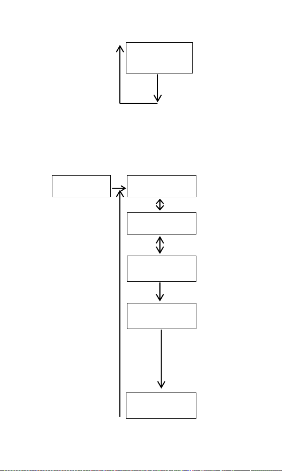
You will view the following screens:
*BT701
BATTERY VOLTS ◄►
BATTERY TES TER
××.×× V
LANGUAGE ◄►↵
SELECT
LANGUAGE ◄►↵
ENGLISH
2006/11/25 ◄►↵
(Time Setting)
↵
* Press ◄ / ► to
select language.
* Press “Enter” to
battery test.
* Press “Enter” to set
language.
* Press ◄ / ► back
to battery test.
* Press ◄ / ► to
select language
( English, French,
German, Spanish,
Italian, Portuguese,
Japanese, Dutch &
Chinese.)
* Press “Enter” to
confirm choice & go
back to battery test.
Press «ENTER» to
confirm Time Setting
Press ◄ / ► to
adjust “Year”.
Press «ENTER» to
finish ”Year” setting &
enter ”Month” setting.
Please follow previous
step to finish “Day”,
”Hour”& ”Minute”
setting.
After finishing
“Minute” setting,
press “Enter” to
battery test
- GB.5-V1 -
BRIGHTNESS
◄ ADJUST ►
*BT747
SYSTEM ANALYZER
BATTERY TES T◄►
××.×× V
SYSTEM TEST◄►
××.×× V
LANGUAGE ◄►↵
SELECT
LANGUAGE ◄►↵
ENGLISH
2006/11/25 ◄►↵
(Time Setting)
Press «ENTER» to
confirm the
brightness setting
Press ◄ / ► to
adjust the brightness
of the display. Press
“Enter” to confirm the
brightness & go back
to battery test.
* Press ◄ / ► to
↵
select language or
system test.
* Press “Enter” to do
battery test.
* Press ◄ / ► to
↵
select battery test
or language
* Press “Enter” to do
system test.
* Press ◄ / ► to
select battery test
or system test.
* Press “Enter” to
set language.
* Press ◄ / ► to
select language.
( English, French,
German, Spanish,
Italian, Portuguese,
Japanese, Dutch &
Chinese.)
* Press “Enter” to
confirm choice &
go back to battery
test.
Press «ENTER» to
confirm Time
Setting
- GB.6-V1 -

BRIGHTNESS
◄ ADJUST ►↵
6.
Press the ◄ ► key to select battery test. Press
«ENTER» button. Example :
7.
Press the ◄ ► key to select
the battery type:
a. REGULAR LIQUID
b. AGM FLAT PLATE
c. AGM SPIRAL
d. VRLA/GEL
Press «ENTER» to confirm choice.
7.
Press the ◄ ► key to select
the battery rating: SAE, EN,
IEC, DIN or JIS
Press «ENTER» to confirm choice.
Press ◄ / ► to
adjust “Year”.
Press «ENTER» to
finish ”Year” setting
& enter ”Month”
setting. Please
follow previous step
to finish “Day”,
”Hour”& ”Minute”
setting.
After finishing
“Minute” setting,
press “Enter” to
battery test
Press «ENTER» to
confirm the
brightness setting
Press ◄ / ► to
adjust the brightness
of the display. Press
“Enter” to confirm the
brightness & go back
to battery test.
BATTERY TYPE ◄►↵
AGM FLAT PLATE
SELECT RATING ◄►↵
SAE
- GB.7-V1 -

8.
Press the ◄ ► key to input
the battery capacity of CCA:
• SAE:40~2000
• EN:40~2100
• IEC:30~1500
• DIN:25~1300
• JIS:By Battery Type No.
Press «ENTER» to begin the test.
9.
Test the battery for few
SET CAPACITY ◄►↵
×××× SAE
seconds.
10.
Press the ◄ ► key to select
battery fully charged or not if
tester asks. Press «ENTER»
IS BATTERY ◄►↵
CHARGED? YES
to confirm choice.
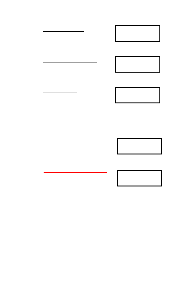
11.
When the test is completed, the display shows the
actual volts and the actual CCA or %. {Press the◄ ►
key to select: SOH (STATE OF HEALTH) or SOC
(STATE OF CHARGE)}.
One of six results will be displayed:
GOOD & PASS :
The battery is good & capable
GOOD & PASS
××.××V ×××× SAE
of holding a charge.
GOOD & RECHARGE :
The battery is good but needs
GOOD & RECHARGE
××.××V ×××× SAE
to be recharged.
RECHARGE & RETEST :
Battery is discharged, the
RECHARGE & RETEST
××.××V ×××× SAE
battery condition cannot be
determined until it is fully charged. Recharge & retest
the battery.
TESTING
- GB.8-V1 -
BAD & REPLACE :
The battery will not hold a
BAD & REPLACE
××.××V ×××× SAE
charge. It should be replaced
immediately.
BAD CELL & REPLACE :
The battery has at least one
BAD CELL & REPLACE
××.××V ×××× SAE
cell short circuit. It should be
replaced immediately.
LOAD ERROR :
The tested battery is bigger
LOAD ERROR
than 2000CCA or 200AH. Or
the clamps are not connected properly. Please fully
charge the battery and retest after excluding both
previous reasons. If reading is the same, the battery
should be replaced immediately.
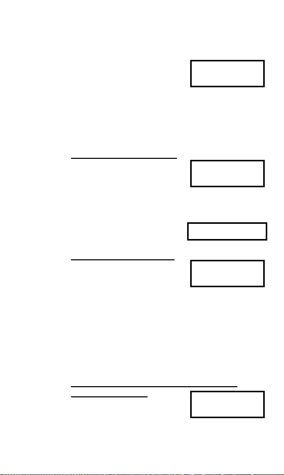
12.
Press the ◄ ► key to select
result printing: YES or NO.
Press «ENTER» to confirm
PRINT RESULT? ◄►
NO
your choice.
↵
※ 24V System Test Printing:
The
printer will not function
for 24
Volt batteries system
PRINT 24V SYSTEM
RESULT? YES
test printing. The 24V system
test result will be recorded till you hook up to a
12V battery and the right screen shows up. Please
select “YES” and press enter key to print the result
and then disconnect the clamps. The screen will
appear again after you reconnect the clamps.
Please select “NO” and press the enter key to go
back to the main menu.
13.
Press «ENTER» return to step 5 or remove the test
clamps from the battery posts after completion of testing
batteries to end test.
- GB.9-V1 -

SYSTEM TEST - BT747 Example :
1.
Press «ENTER» button, you
will view the following screen:
2.
Turn off all vehicle accessory
loads such as light, air
conditioning, radio, etc. Before
start the engine.
3.
When the engine is started, one of the three results will
SYSTEM TEST
××.××V
TURN OFF LOADS
START ENGINE
be displayed along with the actual reading measured.
CRANKING VOLTS NORMAL
The system is showing normal
CRANKING VOLTS
××.××V NORMAL
draw. Press «ENTER» to
perform the charging system test.
CRANKING VOLTS LOW
The cranking voltage is below
CRANKING VOLTS
××.××V LOW
normal limits, troubleshoot the
starter with manufacturers recommended procedure.
CRANKING VOLTS NO
DETECTED
CRANKING VOLTS
NO DETECTED
The cranking voltage is not
detected.
4.
If the cranking voltage is
normal, press «ENTER» to
begin charging system test.
5.
Press the «ENTER» key, you
will view the following screen.
6.
Press the «ENTER» key, one
PRESS ENTER FOR
CHARGING TEST
MAKE SURE ALL
LOADS ARE OFF
of the three results will be displayed along with the
actual reading measured.
- GB.10-V1 -

LOW CHARGING VOLTS WHEN TEST AT IDLE
The alternator is not providing
sufficient current to the battery.
Check the belts to ensure the
ALT. IDLE VOLTS
××.××V LOW
alternator is rotating with engine running. If the belts are
slipping or broken, replace the belts and retest. Check
the connections from the alternator to the battery. If the
connection is loose or heavily corroded, clean or
replace the cable and retest. If the belts and
connections are in good condition, replace the
alternator.
CHARGING SYSTEM NORMAL WHEN TEST AT IDLE
The system is showing normal
output from the alternator. No
ALT. IDLE VOLTS
××.××V NORMAL
problem is detected.
HIGH CHARGING VOLTS WHEN TEST AT IDLE
The voltage output from the
alternator to the battery
exceeds the normal limits of a
ALT. IDLE VOLTS
××.××V HIGH
functioning regulator. Check to ensure there is no loose
connection and the ground connection is normal. If
there is no connection issue, replace the regulator.
Since most alternators have the regulator built-in, this
will require you to replace the alternator. The normal
high limit of a typical automotive regulator is 14.7 volts
+/- 0.05. Check manufacturer specifications for the
correct limit, as it will vary by vehicle type and
manufacturer.
7.
Following the charging system
at idle, press «ENTER» for the
charging system with
TURN ON LOADS
AND PRESS ENTER
accessory loads. Turn on the blower to high (heat),
highbeam headlights, and rear defogger. Do not use
cyclical loads such as air conditioning or windshield
- GB.11-V1 -
wipers.
8.
When testing older model
diesel engines, the users need
to run up the engine to 2500
RUN ENGINE UP TO
2500 RPM 15 SEC.
rpm for 15 seconds. You will view the screen as follows:
9.
Press «ENTER» to look for the amount of ripple from the
charging system to the battery. One of two testing
results will be displayed along with the actual testing
measured.
RIPPLE DETECTED NORMAL
Diodes function well in the
alternator / stator.
RIPPLE DETECTED
××.××V NORMAL
Or
NO RIPPLE DETECT
EXCESS RIPPLE DETECTED
One or more diodes in the
alternator are not functioning
RIPPLE DETECTED
××.××V HIGH
or there is stator damage.
Check to ensure the alternator mounting is sturdy and
that the belts are in good shape and functioning properly.
If the mounting and belts are good, replace the
alternator.
10.
Press the «ENTER» key to continue the charging
system with accessory loads. One of the three results
will be displayed along with the actual testing measured.
CHARGING SYSTEM HIGH WHEN TEST WITH
ACCESSORY LOADS
The voltage output from the
ALT. LOAD VOLTS
××.××V HIGH
alternator to the battery
exceeds the normal limits of a functioning regulator.
- GB.12-V1 -

Check to ensure there are no loose connections and
that the ground connection is normal. If there are no
connection issues, replace the regulator. Since most
alternators have the regulator built-in, this will require
you to replace the alternator.
CHARGING SYSTEM LOW WHEN TEST WITH
ACCESSORY LOADS
The alternator is not providing
ALT. LOAD VOLTS
××.××V LOW
sufficient current for the
system’s electrical loads and the charging current for
the battery. Check the belts to ensure the alternator is
rotating with the engine running. If the belts are slipping
or broken, replace the belts and retest. Check the
connections from the alternator to the battery. If the
connection is loose or heavily corroded, clean or
replace the cable and retest. If the belts and
connections are in good working condition, replace the
alternator.
CHARGING SYSTEM NORMAL WHEN TEST WITH
ACCESSORY LOADS
The system is showing normal
output from the alternator. No
ALT. LOAD VOLTS
××.××V NORMAL
problem detected.
11.
Press «ENTER» when
charging system test is
TEST OVER. TURN
OFF LOADS & ENGINE
completed finish. Turn all
accessory loads and engine off. Press «ENTER» to
return to step 1 or remove the test clamps from the
battery posts after completion of testing to end test.
- GB.13-V1 -

What is a GEL battery?
A gel battery is a lead-acid electric storage battery that:
z is sealed using special pressure valves and should never
be opened.
z is completely maintenance-free.*
z uses thixotropic gelled electrolyte.
z uses a recombination reaction to prevent the escape of
hydrogen and oxygen gases normally lost in a flooded
lead-acid battery (particularly in deep cycle applications).
z is non-spillable, and therefore can be operated in virtually
any position. However, upside-down installation is not
recommend-ed.
Connections must be retorqued and the batteries should
GLOSSARY
be cleaned periodically.
What is an AGM battery?
An AGM battery is a lead-acid electric storage battery that:
z is sealed using special pressure valves and should never
be opened.
z is completely maintenance-free.*
z has all of its electrolyte absorbed in separators consisting
of a sponge-like mass of matted glass fibers.
z uses a recombination reaction to prevent the escape of
hydrogen and oxygen gases normally lost in a flooded
lead-acid battery (particularly in deep cycle applications).
z is non-spillable, and therefore can be operated in virtually
any position. However, upside-down installation is not
recommended.
Connections must be retorqued and the batteries should
be cleaned periodically.
What is a VRLA battery?
Valve Regulated Lead Acid Battery – This type of battery is
sealed Maintenance Free with a “Bunce” Valve or Valves in
the top of them that opens when a preset pressure is realized
inside the battery and let’s the excess gas pressure out.
Then the valve resets itself.
- GB.14-V1 -

What is a SLI battery?
These initials stand for Starting, Lighting and Ignition, which
are the three basic functions which a battery has to perform
on all normal vehicles. Batteries given this description will
have been specifically designed for service on cars and trucks
within a voltage controlled electrical system. Those SLI
batteries which are intended for heavy haulage vehicles fitted
with large diesel motors may often be called COMMERCIAL
batteries. They have to be much more powerful and more
robust than batteries intended for cars.
What is STATE OF HEALTH?
It means how much battery capacity is left (%) comparing
with the marked original battery capacity.
What is STATE OF CHARGE?
It means how many percent of the battery is actually
charged.
What is CCA (COLD CRANKING AMPS)?
The current in amperes which a new fully charged battery
can deliver for 30 seconds continuously without the terminal
voltage falling below 1.2volts per cell, after it has been cooled
to 0OF and held at that temperature. This rating reflects the
ability of the battery to deliver engine starting currents under
winter conditions.
What is AMPERE-HOUR?
The unit of measurement of electrical capacity. A current of
one ampere for one hour implies the delivery or receipt of
one ampere-hour of electricity. Current multiplied by time in
hours equals ampere-hours.
TERMS AND CONDITIONS OF WARRANTY
Any battery tester defective in material or workmanship will be
repaired or replaced according to published defective return test
repair procedures. The existence of a defect shall be determined
by the seller in accordance with published procedures. The
- GB.15-V1 -

published test procedures are available upon request.
This warranty does not cover any unit that has been damaged
due to accident, abuse, alternation, use for a purpose other than
that for which it was intended, or failure to follow operating
instructions. This warranty is expressly limited to original retail
buyers. This warranty is not assignable or transferable. Proof of
purchase is required for all alleged claims. Warranty cannot be
authorized without proof of purchase. Warranty claims must be
sent pre-paid with dated proof of purchase. Damage incurred
during shipment is the responsibility of the shipper (customer
returning unit) If the returned unit qualifies for warranty, the
shipper will only incur shipping cost. The seller reserves the right
to substitute or offer alternative warranty options at its discretion.
The sole and exclusive remedy for any unit found to be defective
is repair or replacement, at the option of the seller. In no event
shall the seller be liable for any direct, indirect, special, incidental,
or consequential damages (including lost profit) whether based
on warranty, contract, tort, or any other legal theory.
RETURN GOODS:
Pack with sufficient over-pack to prevent damage during shipment.
Damage incurred during return shipment is not covered under this
warranty. Repair costs for such damages will be charged back
to shipper.
REMARK:
WHEN RETURNING GOODS, PLEASE SHOW “RETURN
GOODS” ON ALL INVOICES & RELATED SHIPPING
DOCUMENTS TO PREVENT ANY EXTRA CHARGE.”
- GB.16-V1 -
 Loading...