


Infra Red Basin Tap
IR180CP.1 Battery Operated
Installation and Maintenance Instructions
In this procedure document we have endeavoured to make the
information as accurate as possible.
We cannot accept any responsibility should it be found that in
any respect the information is inaccurate or incomplete or
becomes so as a result of further developments or otherwise.
© Intatec Ltd. 2015
Intatec Ltd
Airfield Industrial Estate
Hixon
Staffordshire
ST18 0PF
Tel: 01889 272 180
Fax: 01889 272 181
email: sales@intatec.co.uk
web: www.intatec.co.uk

Introduction
These instructions cover the installation, operation and maintenance of the IR180CP infra red
tap. Please read the enclosed instructions before commencing the installation of this product,
please note;
We recommend that the installation of any Inta product is carried out
by an approved installer.
The installation must be carried out strictly in accordance with the Water Supply (Water Fitting)
Regulations 1999 and any local authority regulations.
If in doubt we recommend that you contact WRAS - Water Regulations Advisory Scheme on
Tel: 0333 207 9030, your local water authority - details available on the WRAS website or
the Chartered Institute of Plumbing and Heating Engineers on Tel: 01708 472 791.
Products
Infra Red Basin Tap IR180CP.1
Check Content
Before commencing remove all components from packaging and check each component with
the contents list.
Ensure all parts are present, before discarding any packaging. If any parts are missing, do not
attempt to install your Inta shower valve until the missing parts have been obtained.
Technical Data
Operating water pressure range: 1 to 8 bar (recommended max 5 bar)
With water pressure in excess of 8 bar
use with a pressure reducing valve
Water temperature operating range: 5 to 65 °C
Power supply: 6V lithium battery mod. CRP-2 or
230V AC main powered / 6V DC
w/safety device anti black-out.
Operating
Putting your hands under the aerator and infront of the sensor starts the water flow.
The tap shuts off when hands are removed or after one minute of water flow.
The mixed water temperature can be increased or reduced by adjusting the lever on the side of
the tap.
© Intatec Ltd 2015
1
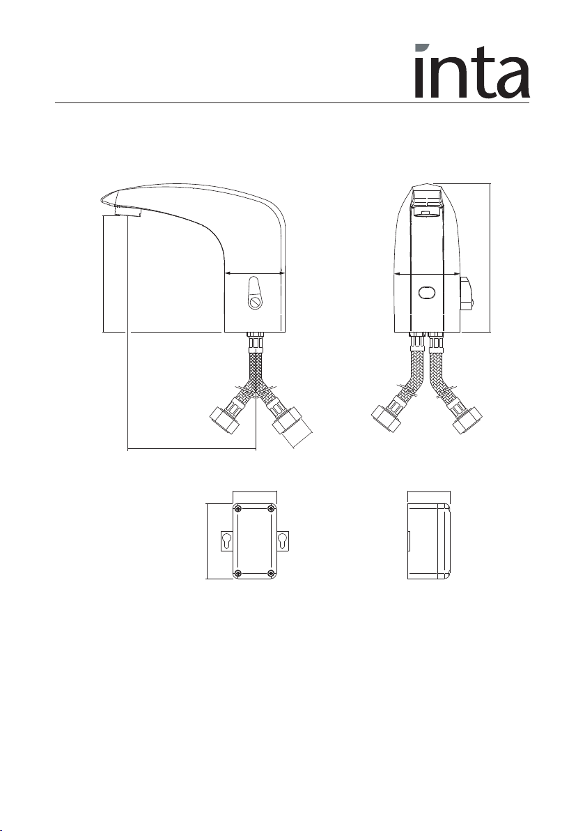
Dimensions
108
56
G½
119
137
60
40.5
39
70
© Intatec Ltd 2015
2

Components
2
57
6
8
3
4
1
Item Qty Component Item Qty Component
1 1 Tap 52Stainless steel flexible hose
2 1 Fixing kit 62Inlet nut
3 1 Battery box 72Sealing washer
4 2 Wall plug and fixing screw 81Power cable
© Intatec Ltd 2015
3

Pre-installation Information
Warning
• Do not install the tap facing a mirror or any other electronic system operated by an infra red
sensor.
• To prevent reflection problems, it is recommended to keep a minimum distance of 1.5m
between the tap and other objects.
• Do not expose the tap to temperatures lower than 5°C (for example during winter time):
otherwise arrange for the system to be drained.
• Adequate provision must be made to ensure the water quality (including limescale); the
presence of debris may damage the solenoid valve.
• For pre-mixed water a thermostatic mixing valve with integral isolating valves should be
installed in the supply pipe to the HOT connection of the tap.
• We recommend that a service valve and check valve are installed in the supply pipe to the
COLD connection of the tap should maintenance be required in the future.
Preparation for installation
Flush the water supply pipes thoroughly prior to installation. Do not allow debris, PTFE tape or
any metal particles to enter the tap.
Turn off the water supply.
Important - All plumbing to be installed in accordance with applicable codes and regulations.
Installation
FAILURE TO OBSERVE THE INSTALLATION INSTRUCTIONS WILL INVALIDATE THE PRODUCT
WARRANTY CONDITION.
1 Screw the flexible hoses (5) into the inlet nuts (6) and the threaded rod from the fixing kit
into the base of the tap.
2 Locate the ‘O’ ring from the fixing kit into recess in the base of the tap.
3 Position the tap (1) into the hole in the basin and secure using the horse shoe washer and
retaining nut from the fixing kit (2).
4 Connect the flexible hoses (5) to the water supplies using the ½” sealing washers (7) and
make water tight joints.
ATTENTION: failure to fit filters on the supply pipes can damage the solenoid valve and
automatically invalidate the product warranty.
5 Fix the power supply unit (3) using the screws (4), ensuring the power cable exits from the
bottom as shown.
ATTENTION: Do not connect the power supply until it required.
© Intatec Ltd 2015
4

Activating
1 Check that the sensor windows is cleaned and remove any potential objects.
2 Open the isolation valves on the water supplies.
3 Fit the batteries inside the box/power supply unit, connect cable from the power supply unit
(3) to the cable (8) from the tap.
4 The LED in the sensor window flashes: when it stops flashing the taps is ready for use.
Setting the Detecting Distance
The detecting distance of the sensor is set at 12 cm but can be reset by the user from a
minimum of 5cm to a maximum of 25 cm (approximately).
1 Remove the battery from the box or turn off the power at the socket.
2 Wait 30 seconds and reconnect the power supply.
3 When the red LED flashes (if it switches off, it is necessary to remove the battery from the
box and repeat the operation), put one hand immediately in front of the sensor (at a
distance of max. 5cm.
4 When the red LED lights up permanently, move your hand to the desired distance.
5 Wait for the LED to switching off before removing your hand, at this point the new distance
is recorded. This new setting will be stored in case of battery replacement (or lacking of
electricity).
Safety Device
To prevent flooding of the premises following an act of vandalism or misuse (an object left in
front of the sensor or a dirty sensor), the tap has a safety device that shuts off the water flow
after about one minute.
Once the object has been removed (or the sensor has been cleaned), the tap starts working
again. Taps with a power supply unit have an anti black-out function which ensures the water
flow stop if the electricity supply fails and prevent it starting again until the electricity supply
has been restored.
Maintenance
Cleaning
In order to keep the tap operating efficiently and maintain its appearance it is necessary to
periodically carry out a number of simple maintenance operations including:
The high quality chrome finish and the darkened plastic window which protects the sensor,
must be kept clean to maintain correct operation, both surfaces should be treated with care.
An occasional wipe with a mild washing-up liquid on a soft damp cloth followed by a
thorough rinse and wipe dry with a soft clean cloth is all that is required.
Do not use an abrasive or chemical household cleaner as this may cause
damage to the surface.
© Intatec Ltd 2015
5

Maintenance
Cleaning
ATTENTION: Turn of the water supply at the ball valve before removing the filter.
Some supplies can contain particles and impurities which could damage the solenoid valve.
As part of package, a water supply filter is included which must be kept clean to ensure
maximum water flow.
Clean the filter by washing thoroughly using running water.
Battery Replacement
When the battery is exhausted, the LED flashes continuously and the solenoid valve stops in the
closed position.
Remove the exhausted battery and repeat the operations described in the section “Activating”
in order to re-store the operation of the tap.
Trouble Shooting
The following details are supplied for on site queries, should further assistance be required our
Technical Department can be contacted directly on 01889 272199
Fault Cause Solution
The isolation valves are closed Open the isolation valves
Exhausted battery (LED flashes) Replace the battery
Check the voltage
Disconnect and reconnect the battery (where
applicable)
Check the connections and the cable’s
integrity
Damaged sensor: ask for assistance
Close the isolation valves and clean the
filters
Ask for assistance
No water flow
The water flows for 1
minute (without
any object in front of the
sensor), finally stops
The water flows for more
than 1 minute
Electrical problem
Dirty sensor Clean the sensor window
Filters are dirty
Blocked solenoid valve Ask for assistance
Dirty Sensor Clean the sensor window
Light reflection on the sensor Remove the reflective surface
Electronic problem Disconnect and reconnect the battery
Blocked solenoid valve /
damaged sensor
© Intatec Ltd 2015
9

Warranty
Limited Warranty
This product is covered by a limited warranty for one year from the date of purchase.
During this period Intatec Ltd undertakes, at its option, to repair or replace any faults caused
by defective material or manufacturing that may arise (see Intatec Warranty).
The warranty does not cover dame caused by;
Abnormal or improper use.
Incorrect installation or water system problems.
Normal wear or negligence in maintenance and in use.
Acts of vandalism
Contact with abrasives, corrosive chemicals or unsuitable cleaning agents or instruments.
Please leave this Manual for the User
To activate your product warranty please visit
www.intatec.co.uk
and click on Product Registration
E & O.E
© Intatec Ltd 2015
Intatec Ltd
Airfield Industrial Estate
Hixon
Staffordshire
ST18 0PF
Tel: 01889 272 180
Fax: 01889 272 181
email: sales@intatec.co.uk
web: www.intatec.co.uk
17-08-15
 Loading...