

Thermostatic Shower Valve
10019CP
Installation and Maintenance Instructions
In this procedure document we have endeavoured to make the
information as accurate as possible.
We cannot accept any responsibility should it be found that in any
respect the information is inaccurate or incomplete or becomes so as a
result of further developments or otherwise.
© Intatec Ltd 2009
Intatec Ltd
Airfield Industrial Estate
Staffordshire
ST18 0PF
01889 207200
Tel:
01889 271172
Fax:
email:
sales@intatec.co.uk
www.intatec.co.uk
web:
Hixon

Introduction
This installation guide has been produced for the 10019CP thermostatic shower with concealed supply pipes
and covers the installation, operation and maintenance.
Please read the enclose instructions before commencing installation
WE RECOMMEND THAT THE INSTALLATION OF ANY INTA PRODUCT IS CARRIED OUT
BY AN APPROVED INSTALLER.
Please read the enclosed instructions before commencing the installation of this product please note;
• The installation must be carried out strictly in accordance with the Water Supply (Water Fittings)
Regulations 1999 and any local water authority regulations.
• If in any doubt, we recommend that you should contact either your local water authority, the secretary
of the Water Regulations Committee at the WRc on Tel: 01495 248454 or The Institute of Plumbing on
Tel: 01708 472791.
• Please check that all the components are in the box, before commencing installation.
.
Technical Specification
This thermostatic shower valve is suitable for use on all common types of plumbing system including gravity
supplies, fully pumped, modulating combination boilers, unvented water heaters and unbalanced supplies i.e.
cold mains & tank fed hot. They are not suitable for non-modulating combination boilers.
Designated Pressure LP & HP
Max. Static Pressure 10 bar
Temperature Stability
Inlet Temperature Range 55˚C to 65˚C: Hot Supply
BS EN 1111 Working Pressure Ranges 0.5 to 5.0 High Pressure
Min Temp Differential (Mix to Hot) for fail-safe 10˚C
Max. Pressure Inlet Differential 5:1
Preset Temperature 38˚C
±
2˚C
≤ 25˚C: Cold Supply
Preparation for Installation
• Ensure all the parts are present before commencing the installation of any Inta product.
• Before commencing the installation ensure the site conditions are suitable.
• The hot and cold supply pipes can be concealed behind a stud wall or embedded into the a solid
wall.
• When installing, care must be taken not to damage / affect the finish of this product.
• Service valves must be installed in both the hot and cold water supply pipes, in order to isolate
the shower valve should serviceing be required in the future.
• Flush the water supply pipes thoroughly prior to installation. Do not allow debris, PTFE or any
metal particles enter the shower valve.
• Turn off the water supply.
1
© Intatec Ltd 2009
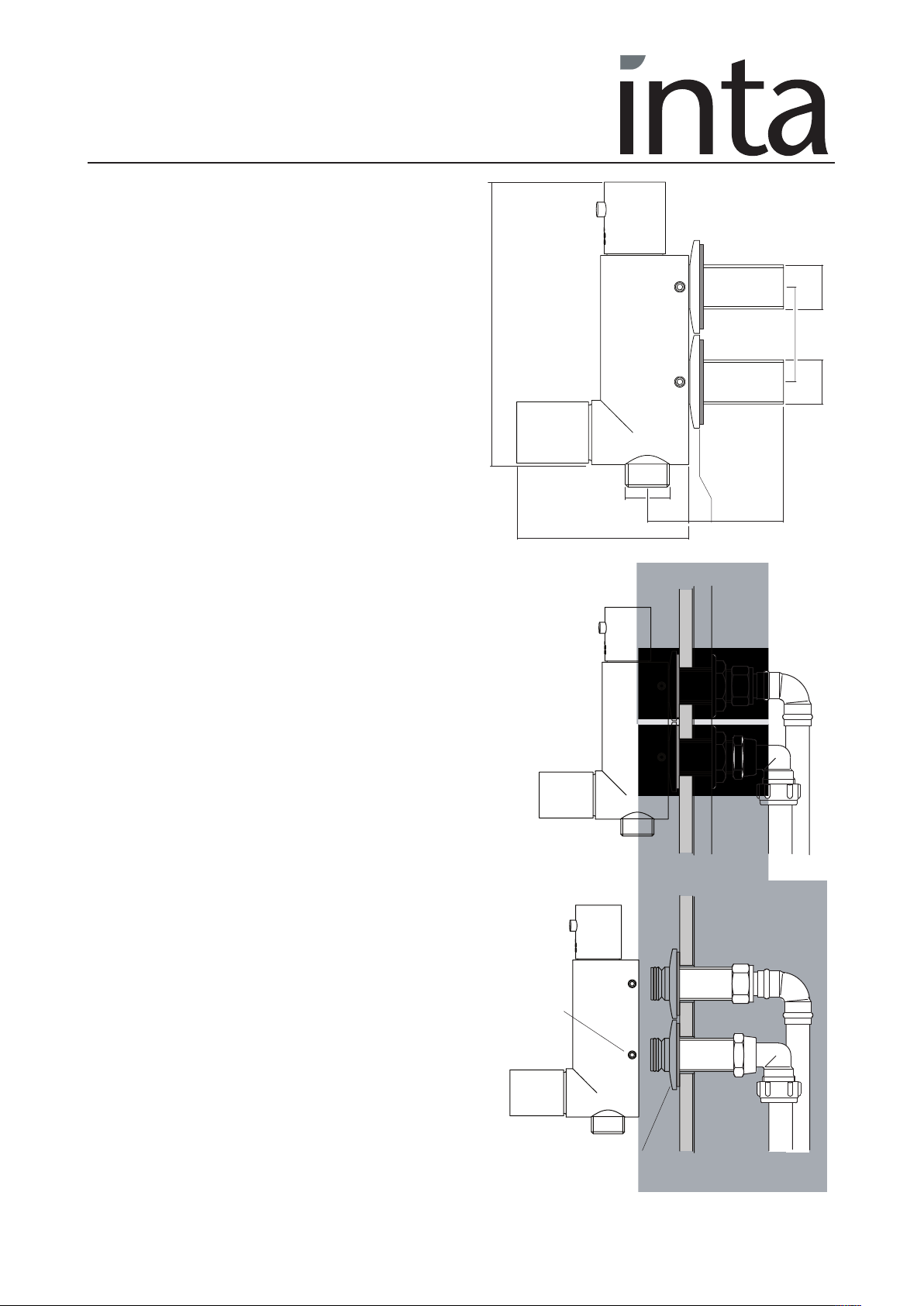
Installation Instructions
Stud Wall
Installation with the supply pipes concealed behind
a stud wall.
Cut 2 holes 24 to 26mm in diameter at 45mm
centres in the plaster board or wall plate.
Finish tiling the wall cutting 2 holes 24mm to 26mm
in the tiles.
Insert the shower valve through the two holes and
secure with the 2 back nuts, do not over tighten.
Connect the hot supply to the lower inlet and the
cold to the upper.
A swivel to copper connector or an olive and
compression nut are 2 typical fittings for making the
connections.
145
45 Ctr
/2B
1
/2B G
1
G
Cold Inlet
Hot Inlet
1
B
/2
G
19.5
82
40
5
Connect the flexible hose of the shower kit to the mixed
water outlet and secure the rail to the wall.
Turn on the water supplies and check joints for leakage.
Solid Wall
Installation with the supply pipes embedded into a solid wall.
Cut a channel into the wall for the supply pipes allowing
sufficient depth to position the concealing plates to as shown
on the finished tiled surface.
Connect the supply pipes to the valve and turn of the water
supplies and check for leakage from any joints.
Turn off the water supplies.
Unscrew the two socket set screws and carefully remove the
body and concealing plates.
Fill the channel and finish tiling the wall.
Seal the holes between inlets and tiles with silicone
sealer.
Refit the concealing plates and push firmly to the wall
surface.
Carefully refit the valve and re-tighten the socket set
screws.
Socket
set screw
Mixed water
outlet
Plaster board
and tiled wall
Olive and
comp. nut
Swivel
connector
Connect the flexible hose of the shower kit to the mixed
water outlet and secure the rail to the wall.
Turn on the water supplies and check for correct
operation.
© Intatec Ltd 2009
Concealing
plate
2

Operation
The red button on the temperature control knob locks the mixed water temperature to 38˚C, press the
button to release the knob to increase the or lower the water temperature.
Turning the flow control knob anti-clockwise turns on the water and regulates the amount flowing.
Components
Cover
Retaining
screw
Temperature
control knob
Thermostatic
cartridge
Non turn
valve
Retaining
screw
Filter
Flow control
valve
Cover
Control
knob
Flow Control Valve Replacement
Isolate both the hot and cold water supplies
Remove the cover and unscrew the control knob retaining screw and remove the flow control knob.
Using a suitable spanner unscrew the flow control valve.
Replace with a new valve or replace the disk washer as required and assemble in the reverse order.
Cartridge Replacement
Isolate both the hot and cold water supplies.
Remove the cover and unscrew the control knob retaining screw and remove the temperature control knob.
Carefully pull the cartridge out of the body
If any of the ‘O’ ring seals or the thermostatic element is blocked or damaged they must be replaced.
Using neutral silicon grease re-lubricate the internal moving components of the valve.
Re-assemble in the reverse order.
The valve must then be re-commissioned following the procedure detailed.
3
© Intatec Ltd 2009

Filter Cleaning and Non Return Valve Removal
Isolate both the hot and cold water supplies and disconnect the shower riser from the body.
Unscrew the 2 socket set screws and carefully pull the body from the inlets.
Carefully pull out the non return valves, flush out any debris and check for correct operation.
Remove the filters and flush thoroughly, remove any debris collected infront of the filter from the inlets.
Replace non return valves and filters if damaged with new.
Re-assemble in the reverse order turn on both supplies and check joints for leakage.
Aftercare
Inta thermostatic shower valves have a high quality finish and should be treated with care.
An occasional wipe with a mild washing-up liquid on a soft damp cloth followed by a thorough rinsing is
all that is required.
Do not use
The following information is required when the thermostatic shower valve is used in a TMV2
Applications under the requirements of BS EN 1111: 1999 “Sanitary tapware – Thermostatic
Mixing Valve (PN 10) – General Technical Specification”.
abrasive
an
chemical household cleaner
or
IMPORTANT
IMPORTANT
as this may
cause damage
.
Supply Conditions
The supply conditions to the Thermostatic Mixing Shower Valve must comply with the following;
Conditions High Pressure
Maximum Static Pressure bar 10
Flow Pressure, Hot & Cold bar 0.5 to 5
Hot Supply Temperature ˚C 55 to 65
Cold Supply Temperature ˚C ≤ 25˚C
Note:
Valves operating outside these conditions cannot be guaranteed by the Scheme to operate as type
2 valves.
• The valves designation of use, HPif tested against BS EN 1111.
• For valves designated for use HP only, if a water supply is fed by gravity then the supply pressures
should be verified to ensure the conditions of use are appropriate for the valve.
Introduction
The thermostatic shower valve has been specifically designed and manufactured to meet the
requirements of BS EN 1111:1999 and TMV2 Type Scheme. The valve has been independently
tested and approved as a TYPE 2 valve under the BuildCert TMV2 scheme by the WRc Testing &
Evaluation Center.
4
© Intatec Ltd 2009

Application
The thermostatic mixing shower valve has been independently tested by WRAS and certified as meeting
the requirements of the BS EN 1111:1999 under the TMV2 Scheme as being suitable for use on the
following designations.
Recommended Outlet Temperatures
The BuildCert TMV scheme recommends the following set maximum mixed water out let temperatures for
use in all premises:
Code Application Recommended Hot Water Temperature
HP-S Shower 41˚C
The mixed water temperature must never exceed 43˚C.
The maximum mixed water temperature can be 2˚C above the recommended maximum set outlet
temperature.
Recommended Outlet Temperatures
Note:
43˚C is the maximum mixed water temperature from the shower. The maximum temperature takes
account of the allowable tolerances inherent in thermostatic shower valves and temperature losses.
It is not a safe bathing Temperature for adults or children
The British Burns Association recommends 37 to 37.5˚C as a comfortable bathing temperature for
children. In premises covered by the Care Standard Act 2000, the maximum mixed water outlet
temperature is 43˚C.
.
Installation
Important
valve. The installer of the thermostatic shower valve must comply with the requirements of the Water supply
(Water Fittings) Regulations 1999 and also be aware of their responsibility and duty of care to ensure that
all aspects of the installation comply with the regulations.
It has been brought to our attention that flushing water systems using certain chemicals may wholly or
partially remove the lubricant from the internal workings of the valve, which may adversely affect its
performance. We recommend that following flushing the system with chemicals; valves are checked for
correct operation.
1. It is essential that before installing any thermostatic shower valve to ensure that the supply conditions of
2. Consideration must be made for the possibility of multiple / simultaneous demands being made on the
: - The following instructions must be read prior to the installation of the thermostatic shower
the system to which the valve is intended to be fitted are checked to confirm compliance with the
parameters as quoted within the technical specification and conditions on which the approval is
granted i.e. verify supply temperatures, supply pressures, risk assessment.
supply system whilst the thermostatic shower valve is in use, all practical precautions must be made to
ensure that the valve is not affected. Failure to make provision within the pipe sizing etc. will affect the
performance of the shower valve.
© Intatec Ltd 2009
5

Installation
3. The supply to which the thermostatic shower valve is to be installed must be thoroughly flushed and
cleaned to remove any debris, which may have accumulated during the installation. Failure to remove
any debris will affect the performance and the manufacturer’s warranty of the product. In areas that are
subject to aggressive water, provision must be made to treat the supplies prior to the supplies entering
the shower valve.
4. The thermostatic shower valve has been designed for vertical installation and surface mounting.
5. The thermostatic shower valve will be installed in such a position that maintenance of its components,
associated valves and the commissioning and testing of the shower valve can be undertaken.
6. The hot and cold water supplies must be connected to the valve strictly in accordance with the
indications on the body of the valve i.e. hot water supply to the hot port of the valve.
7. In a situation where one or both of the water supplies are excessive, it is recommended to fit a Pressure
Reducing Valve to reduce the pressure(s) to within the limits as quoted previously.
8. Any thermostatic shower valve must be fitted with a back flow prevention device, such as check valves
to prevent the cross contamination of supplies. The thermostatic shower valve is supplied complete with
integral insert check valves and strainers.
9. The fitting of isolation valves is required as close as is practicable to the water supply inlets of the
thermostatic shower valve.
10. The fitting of strainers is recommended as close as is practicable to the water supply inlets of the
thermostatic shower valve.
11. It is essential that the fail safe thermostatic shower valve should not be installed in situations where
there is a possibility of the valve being deprived of water or where demands for water are greater than
the actual stored supplies.
12. To ensure that the performance levels of the thermostatic shower valve are maintained (in the event of
cold water failure), the temperature of the hot water supply at the point of entry to the thermostatic
shower valve must be a minimum of 10˚C above the commissioned mixed water discharge
temperature.
13. The fail-safe thermostatic shower valve must not be subject to any extreme temperature variations either
during the installation or under normal operating conditions.
Commissioning
Important:
thermostatic shower valve. If under any circumstances there are aspects to the installation / system which
do not comply with the specification laid down, the valve
system / installation complies with the specification. However if all these conditions are met, proceed to
set the temperature as follows;
1. Ensure that the system is thoroughly cleaned and free from any debris prior to commissioning the
thermostatic shower valve.
- The following instructions must be read and understood prior to commissioning the
MUST NOT
be put into operation until the
© Intatec Ltd 2009
6

Commissioning
2. Commissioning the temperatures must be carried out using a suitably calibrated thermometer –
preferably a digital thermometer. The sensing part of the thermometer probe must be fully submerged in
the water when testing.
3. The valve must be commissioned taking into consideration any fluctuations, which may occur within
the system due to simultaneous demands. It is advisable that any outlets which are connected to the
same supply as the shower valve are open during setting of the mixed water temperature. It is
advisable to ensure that the water temperatures are established before any attempt to commission.
4. Once the supply temperatures are stable and the normal operating conditions are established, the
shower valve can be commissioned. The following sequence should be followed when commissioning
the valve;
4.1 The first step in commissioning a thermostatic shower valve is to check the following:
• The designation of the thermostatic shower valve matches the application
• The supply pressures are within the valve’s operating range.
• The supply temperatures are within the valve’s operating range.
• Isolating valves (and ‘Y’ strainers preferred) are provided.
4.2 If all these conditions are met, proceed to set the temperature as stipulated in the manufacturer’s
installation instructions.
4.3 Measure and record the temperature of the hot and cold water supplies at the connection to the
valve.
4.4 Measure and record the temperature of the water discharging from the valve.
4.4 Isolate the cold water supply to the valve and monitor the mixed water temperature.
4.6 Measure and record the maximum mixed water temperature and the final temperature. The final
temperature found during the test should not exceed the values quoted.
4.7 Record all the equipment used during the commissioning.
4.8 The mixed water temperature at the terminal fitting must never exceed 2˚C above the set
temperature.
5. If the mixed water temperature exceeds the recommended temperature of 41˚C by 2˚C or does not
reach 41˚C the shower valve can be adjusted as follows:
5.1 With stable supply conditions remove the temperature control knob.
5.2 Rotate the temperature control knob by one spline clockwise to increase the temperature and one
spline anticlockwise to reduce it.
5.3 Measure the water discharging from the shower.
5.4 Repeat 5.2 until the desired temperature is stablised and record the temperature.
5.5 Repeat 4.4 and 4.5
5.6 Secure the temperature control knob with the retaining screw and re-fit the cover.
6. The above information must be recorded and updated on every occasion when any
work is carried out on the valve.
© Intatec Ltd 2009
7

In Service Testing
It is a requirement that all TMV2 approved valves shall be verified against the original set temperature
results once a year. When commissioning / testing is due the following performance checks shall be
carried out.
1. Measure the mixed water temperature at the outlet.
2. Carry out the cold water supply isolation test by isolating the cold water supply to the shower, wait for
five seconds if water is still flowing check that the temperature is below 43˚C.
3. If there is no significant change to the set outlet temperature (±2˚C or less from the original settings)
and the fail-safe shut off is functioning, then the valve is working correctly and no further service work
is required.
Notes:
• If there is a residual flow during the commissioning or the annual verification (cold water supply
isolation test), then this is acceptable providing the temperature of the water seeping from the valve
is no more than 2˚C above the designated maximum mixed water outlet temperature setting of the
valve.
• Temperature readings should be taken at the normal flow rate after allowing for the system to
stablise.
• The sensing part of the thermometer probe must be fully submerged in the water that is to be tested.
• Any thermostatic shower that has been adjusted or serviced must be re-commissioned and re-tested
in accordance with the manufacturers’ instructions
E & O.E 02/09
© Intatec Ltd. 2009
Intatec Ltd
Airfield Industrial Estate
Staffordshire
ST18 0PF
01889 207200
Tel:
01889 271172
Fax:
email:
sales@intatec.co.uk
www.intatec.co.uk
web:
Hixon
 Loading...