

Page 1
INSYS Powerline GP
Manual
Page 2

Page 3

Copyright © November 2017 INSYS MICROELECTRONICS GmbH
Any duplication of this manual is prohibited. All rights on this documentation and
the devices are with INSYS MICROELECTRONICS GmbH Regensburg.
Trademarks
The use of a trademark not shown below is not an indication that it is freely availa-
ble for use.
MNP is a registered trademark of Microcom Inc.
IBM PC, AT, XT are registered trademarks of International Business Machine Corporation.
INSYS®, VCom®, e-Mobility LSG® and e-Mobility PLC® are registered trademarks of
INSYS MICROELECTRONICS GmbH.
Windows™ is a registered trademark of Microsoft Corporation.
Linux is a registered trademark of Linus Torvalds.
Publisher:
INSYS MICROELECTRONICS GmbH
Hermann-Köhl-Str. 22
D-93049 Regensburg, Germany
Phone: +49 941 58692 0
Fax: +49 941 58692 45
E-mail: info@insys-icom.com
Internet: http://www.insys-icom.com
Date: Nov-17
Item: 10015596
Version: 1.4
Language: EN
Page 4

Content
4
Nov-17
1 Preface ..................................................................................................... 6
1.1 Defects Liability Terms .......................................................................................... 6
1.2 Feedback ............................................................................................................... 6
1.3 Marking of Warnings and Notes ............................................................................ 7
1.4 Symbols and the Formatting in this Manual .......................................................... 8
2 Safety ....................................................................................................... 9
2.1 Intended Use ......................................................................................................... 9
2.2 Permissible Technical Limits .................................................................................. 9
2.3 Responsibilities of the Operator ........................................................................... 10
2.4 Qualification of the Personnel .............................................................................. 10
2.5 Instructions for Transport and Storage ................................................................ 10
2.6 Markings on the Product ..................................................................................... 11
2.7 Environmental Protection .................................................................................... 11
2.8 Safety Instructions for Electrical Installation ........................................................ 12
2.9 General Safety Instructions .................................................................................. 12
3 Scope of Delivery ................................................................................... 14
4 Technical Data ....................................................................................... 15
4.1 Physical features .................................................................................................. 15
4.2 Technological Features ........................................................................................ 16
4.3 Certifications ........................................................................................................ 16
5 Display and Control Elements ................................................................ 17
5.1 Meaning of the Display Elements ........................................................................ 18
6 Connections ........................................................................................... 19
6.1 Front Panel Connections ...................................................................................... 19
6.2 Terminal Connections on the Bottom .................................................................. 20
6.3 Terminal Connections on the Top ........................................................................ 21
7 Function Overview ................................................................................. 22
8 Assembly ............................................................................................... 23
9 Function ................................................................................................. 29
9.1 Firmware Update ................................................................................................. 29
9.2 Configuration ....................................................................................................... 29
9.2.1 Configuration using devolo dLAN SDK .................................................. 29
9.2.2 Configuration using open-plc-utils ......................................................... 32
9.3 SLAC Protocol ..................................................................................................... 35
9.3.1 SLAC Interface ....................................................................................... 36
9.3.2 Commands ............................................................................................. 45
Page 5

Contents
Nov-17 5
10 Maintenance, Repair and Troubleshooting ............................................. 52
10.1 Maintenance ........................................................................................................ 52
10.2 Troubleshooting ................................................................................................... 52
10.3 Repair .................................................................................................................. 52
11 Waste Disposal ...................................................................................... 53
11.1 Repurchasing of Legacy Systems ........................................................................ 53
12 Declaration of Conformity ...................................................................... 54
13 Licenses ................................................................................................. 55
14 Tables and Diagrams.............................................................................. 72
14.1 List of Tables ....................................................................................................... 72
14.2 List of Diagrams .................................................................................................. 73
15 Index ...................................................................................................... 74
Page 6

Preface
INSYS Powerline GP
6
1 Preface
This manual allows for the safe and efficient use of the product. The manual is part
of the product and must always be stored accessible for installation, commissioning and operating personnel.
1.1 Defects Liability Terms
A usage not according to the intended purpose, an ignorance of this documentation, the use of insufficiently qualified personnel as well as unauthorised modifications exclude the liability of the manufacturer for damages resulting from this. The
liability of the manufacturer ceases to exist.
The regulations of our Delivery and Purchasing Conditions are effective. These can
be found on our website (www.insys-icom.de/imprint/) under “General Terms and
Conditions“.
1.2 Feedback
We are permanently improving our products and the associated technical documentation. Your feedback is very helpful for this. Please tell us what you like in particular on our products and publications and what can be improved from your point
of view. We highly appreciate your suggestions and will include them in our work
to support you and all our customers. We are looking forward to any of your feedback.
Please send an e-mail to support@insys-tec.de.
We'd like to know your applications. Please send us a few headwords that we
know the applications you solve using products of INSYS icom.
Page 7

INSYS Powerline GP
Preface
7
1.3 Marking of Warnings and Notes
Symbols and Key Words
Danger!
Risk of severe or fatal injury
One of these symbols in conjunction with the key word
Danger indicates an imminent danger. It will cause death
or severe injuries if not avoided.
Warning!
Personal injury
This symbol in conjunction with the key word Warning
indicates a possibly hazardous situation. It might cause
death or severe injuries if not avoided.
Caution!
Slight injury and / or material damage
This symbol in conjunction with the key word Caution
indicates a possibly hazardous or harmful situation. It
might cause slight or minor injuries or a damage of the
product or something in its vicinity if not avoided.
Note
Improvement of the application
This symbol in conjunction with the key word Note
indicates hints for the user or very useful information. This
information helps with installation, set-up and operation of
the product to ensure a fault-free operation.
Page 8

Preface
INSYS Powerline GP
8
1.4 Symbols and the Formatting in this Manual
This section describes the definition, formatting and symbols used in this manual.
The various symbols are meant to help you read and find the information relevant
to you. The following text is structured like a typical operating instruction of this
manual.
Bold print: This will tell you what the following steps will result in
After that, there will be a detailed explanation why you could perform the
following steps to be able to reach the objective indicated first. You can
decide whether the section is relevant for you or not.
An arrow will indicate prerequisites which must be fulfilled to be able to
process the subsequent steps in a meaningful way. You will also learn
which software or which equipment you will need.
1. One individual action step: This tells you what you need to do at this
point. The steps are numbered for better orientation.
A result which you will receive after performing a step will be marked
with a check mark. At this point, you can check if the previous steps
were successful.
Additional information which you should consider are marked with a
circled "i". At this point, we will indicate possible error sources and tell
you how to avoid them.
➢
Alternative results and steps are marked with an arrow. This will tell
you how to reach the same results performing different steps, or what
you could do if you didn't reach the expected results at this point.
Page 9

INSYS Powerline GP
Safety
9
2 Safety
The Safety section provides an overview about the safety instructions, which must
be observed for the operation of the product.
The product is constructed according to the currently valid state-of-the-art technology and reliable in operation. It has been checked and left the factory in flawless
condition concerning safety. In order to maintain this condition during the service
life, the instructions of the valid publications and certificates must be observed and
followed.
It is necessary to adhere to the general safety instructions must when operating the
product. The descriptions of processes and operation procedures are provided with
precise safety instructions in the respective sections in addition to the general
safety instructions.
Moreover, the local accident prevention regulations and general safety regulations
for the operating conditions of the device are effective.
An optimum protection of the personnel and the environment from hazards as well
as a safe and fault-free operation of the product is only possible if all safety instructions are observed.
2.1 Intended Use
The product may only be used for the purposes specified in the function overview.
In addition, it may be used for the following purposes:
Usage and mounting in a charging station for electric vehicles.
2.2 Permissible Technical Limits
The product is only intended for the use within the permissible technical limits
specified in the data sheets.
The following permissible limits must be observed:
The ambient temperature limits must not be fallen below or
exceeded.
The supply voltage range must not be fallen below or exceeded.
The maximum humidity must not be exceeded and condensate
formation must be prevented.
The maximum switching voltage and the maximum switching current
load must not be exceeded.
The maximum input voltage and the maximum input current must not
be exceeded.
Page 10

Safety
INSYS Powerline GP
10
2.3 Responsibilities of the Operator
As a matter of principle, the operator must observe the legal regulations, which are
valid in his country, concerning operation, functional test, repair and maintenance
of electrical devices.
2.4 Qualification of the Personnel
The installation, commissioning and maintenance of the product must only be performed by trained expert personnel, which has been authorised by the plant operator. The expert personnel must have read and understood this documentation and
observe the instructions.
Electrical connection and commissioning must only be performed by a person, who
is able to work on electrical installations and identify and avoid possible hazards independently, based on professional training, knowledge and experience as well as
knowledge of the relevant standards and regulations.
2.5 Instructions for Transport and Storage
The following instructions must be observed:
Do not expose the product to moisture and other potential hazardous
environmental conditions (radiation, gases, etc.) during transport and
storage. Pack product accordingly.
Pack product sufficiently to protect it against shocks during transport
and storage, e.g. using air-cushioned packing material.
Check product for possible damages, which might have been caused by improper
transport, before installation. Transport damages must be noted down to the shipping documents. All claims or damages must be filed immediately and before installation against the carrier or party responsible for the storage.
Page 11
INSYS Powerline GP
Safety
11
2.6 Markings on the Product
The identification plate of the product is either a print or a label on a face of the
product. Amongst other things, it can contain the following markings, which are
explained in detail here.
Observe manual
This symbol indicates that the manual of the product contains
essential safety instructions that must be followed implicitly.
Dispose waste electronic equipment environmentally
compatible
This symbol indicates that waste electronic equipment must be
disposed separately from residual waste via appropriate collecting
points. See also Section Disposal in this manual.
CE marking
By applying a CE marking, the manufacturer confirms that the
product complies with the European directives that apply productspecific.
UL marking
By applying a UL marking, the manufacturer confirms that the
product complies with the obligatory safety requirements.
Appliance Class II - double insulated
This symbol indicates that the product complies with Appliance
Class II
Appliance Class III - protection by extra low voltage
This symbol indicates that the product complies with Appliance
Class III
2.7 Environmental Protection
Dispose the product and the packaging according to the relevant environmental
protection regulations. The Waste Disposal section in this manual contains notes
about disposing the product. Separate the packaging components of cardboard
and paper as well as plastic and deliver them to the respective collection systems
for recycling.
Page 12
Safety
INSYS Powerline GP
12
2.8 Safety Instructions for Electrical Installation
The electrical connection must only be made by authorised expert personnel according to the wiring diagrams.
The notes to the electrical connection in the manual must be observed. Otherwise,
the protection category might be affected.
The safe disconnection of circuits, which are hazardous when touched, is only ensured if the connected devices meet the requirements of VDE T.101 (Basic requirements for safe disconnection).
The supply lines are to be routed apart from circuits, which are hazardous when
touched, or isolated additionally for a safe disconnection.
An easily accessible isolation device that disconnects all lines must be installed
prior to commissioning of the device to be able to isolate it completely from power
supply.
2.9 General Safety Instructions
Danger!
Potentially lethal operating voltage!
Risk of fatal injury from electric shock.
Prior to the installation, switch the power supply of the
cabinet off and secure it against being switched on again.
Danger!
Exposed electrical components!
Risk of fatal injury from electric shock.
Prior to the installation, switch the power supply of the
cabinet off and secure it against being switched on again.
Warning!
Moisture and liquids from the environment may seep into
the interior of the INSYS Powerline GP!
Risk of fatal injury from electric shock when touching as
well as fire hazard and damage of the product.
The INSYS Powerline GP must not be used in wet or damp
environments, or in the direct vicinity of water. Install the
INSYS Powerline GP at a dry location, protected from
water spray. Disconnect the power supply before you
perform any work on a INSYS Powerline GP which may
have been in contact with moisture.
Page 13

INSYS Powerline GP
Safety
13
Caution!
Short circuits and damage due to improper repairs and
modifications as well as opening of maintenance areas.
Fire hazard and damage of the product.
It is not permitted to open the product for repair or
modification.
Caution!
Overcurrent of the device supply!
Fire hazard and damage of the product due to overcurrent.
The product must be protected against currents exceeding
1.6 A with a suitable fuse. Use an overcurrent protection
device with high interrupting rating (1500 A).
Caution!
Overvoltage and voltage peaks from the mains supply!
Fire hazard and damage of the product due to overvoltage.
Install suitable overvoltage protection.
Caution!
Damage due to chemicals!
Ketones and chlorinated hydrocarbons dissolve the plastic
housing and damage the surface of the device.
Never let the device come into contact with ketones (e.g.
acetone) or chlorinated hydrocarbons, such as
dichloromethane.
Page 14

Scope of Delivery
INSYS Powerline GP
14
3 Scope of Delivery
The scope of delivery for the INSYS Powerline GP includes all accessories listed
below. Please check if all accessories are included in the box. If a part is missing or
damaged, please contact your distributor.
▪ INSYS Powerline GP
Page 15

INSYS Powerline GP
Technical Data
15
4 Technical Data
4.1 Physical features
Danger!
Potentially lethal operating voltage!
Risk of fatal injury from electric shock.
Before working on the INSYS Powerline GP make sure to
disconnect the power supply of the INSYS Powerline GP
and protect it against re-connection.
Caution!
Overvoltage and voltage peaks from the mains supply!
Fire hazard and damage of the product due to overvoltage.
Install suitable overvoltage protection.
All specified data was measured with nominal input voltage, at full load, and an
ambient temperature of 25 °C. The limit value tolerances are subject to the usual
variations.
Physical Feature
Value
Operating voltage
minimum 10 V DC
maximum 60 V DC
Voltage at Powerline connection
0 – 240 V, 50 Hz
Power consumption idle
1.5 W
Power consumption connection
2 W
Weight
160 g
Dimensions (Width x Depth x Height)
45 x 110 x 75 mm
Temperature range
-20 °C – 55 °C
Maximum permissible humidity
95% non-condensing
Protection class
Housing IP40, Terminals IP20
Table 1: Physical Features
Page 16

Technical Data
INSYS Powerline GP
16
4.2 Technological Features
Technological Feature
Description
Compatibility
HomePlug Green PHY™ 1.1
Transmission rates
Up to 10 Mbps on the powerline
(the actual usable data rate is lower due
to the coexistence with HomePlug AV
required in the HomePlug
specifications)
Pilot signal coupling
ISO/IEC 15118-3 compliant The
coupling circuit and filters against
feedback to the charging controller are
already integrated in the INSYS
Powerline GP.
Table 2: Technological Features
4.3 Certifications
The INSYS Powerline GP has been developed in compliance with the following
guidelines and standards:
• DIN EN 55022 Class B
• DIN EN 61000-6-2
• DIN EN 60950-1
Page 17
INSYS Powerline GP
Display and Control Elements
17
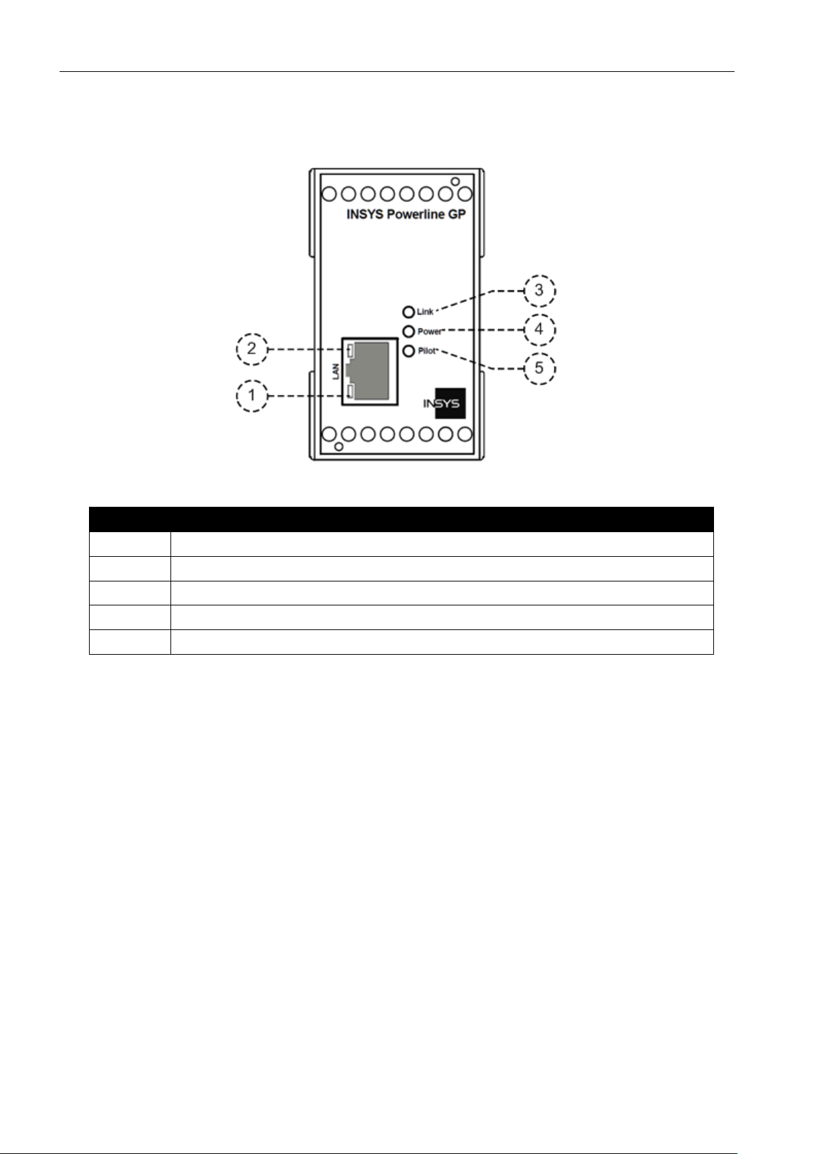
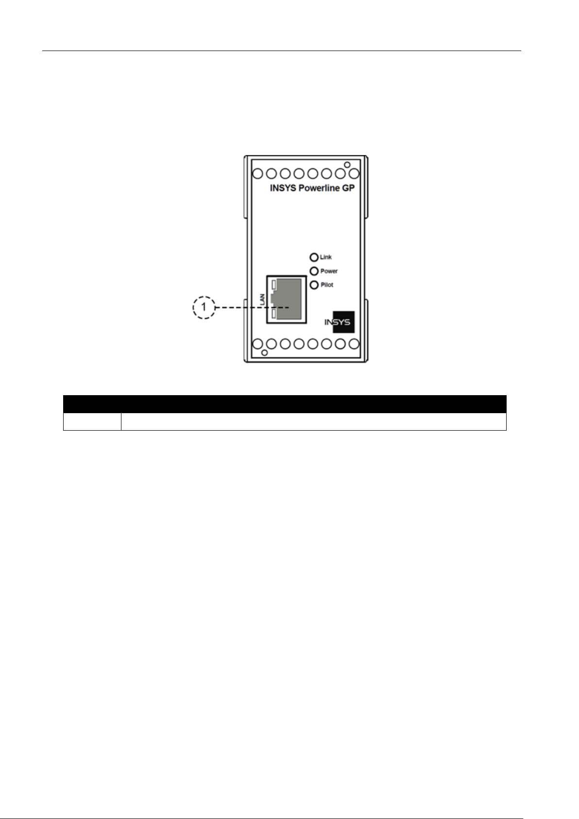
5 Display and Control Elements
Figure 1: LEDs on the front panel
Position
Description
1
Status LED for Ethernet connection (yellow)
2
Status LED for Ethernet connection (green)
3
Link LED
4
Power LED
5
Pilot LED (pilot coupling status)
Table 3: Description of the LEDs on the front panel
Page 18

Display and Control Elements
INSYS Powerline GP
18
5.1 Meaning of the Display Elements
Description
Display
Meaning
Status LED (yellow)
LED on
100 MBit/s connection
LED off
No connection or connection with 10 MBit/s
Status LED (green)
LED on
Connected
LED blinks
Data traffic
LED off
Not connected
Link LED
LED on
Connected to AVLN (AV Logical Network)
LED off
Not connected to AVLN
Power LED
LED on
Supply voltage available
LED off
No supply voltage
Pilot LED
LED on
Powerline signal coupled to pilot line
LED off
Powerline signal coupled to mains line
Table 4: Meaning of the LED displays
Page 19
INSYS Powerline GP
Connections
19
6 Connections
6.1 Front Panel Connections
Figure 2: Connections on the front panel of the device
Position
Description
1
Ethernet connection
Table 5: Connections on the front panel of the device
Page 20
Connections
INSYS Powerline GP
20
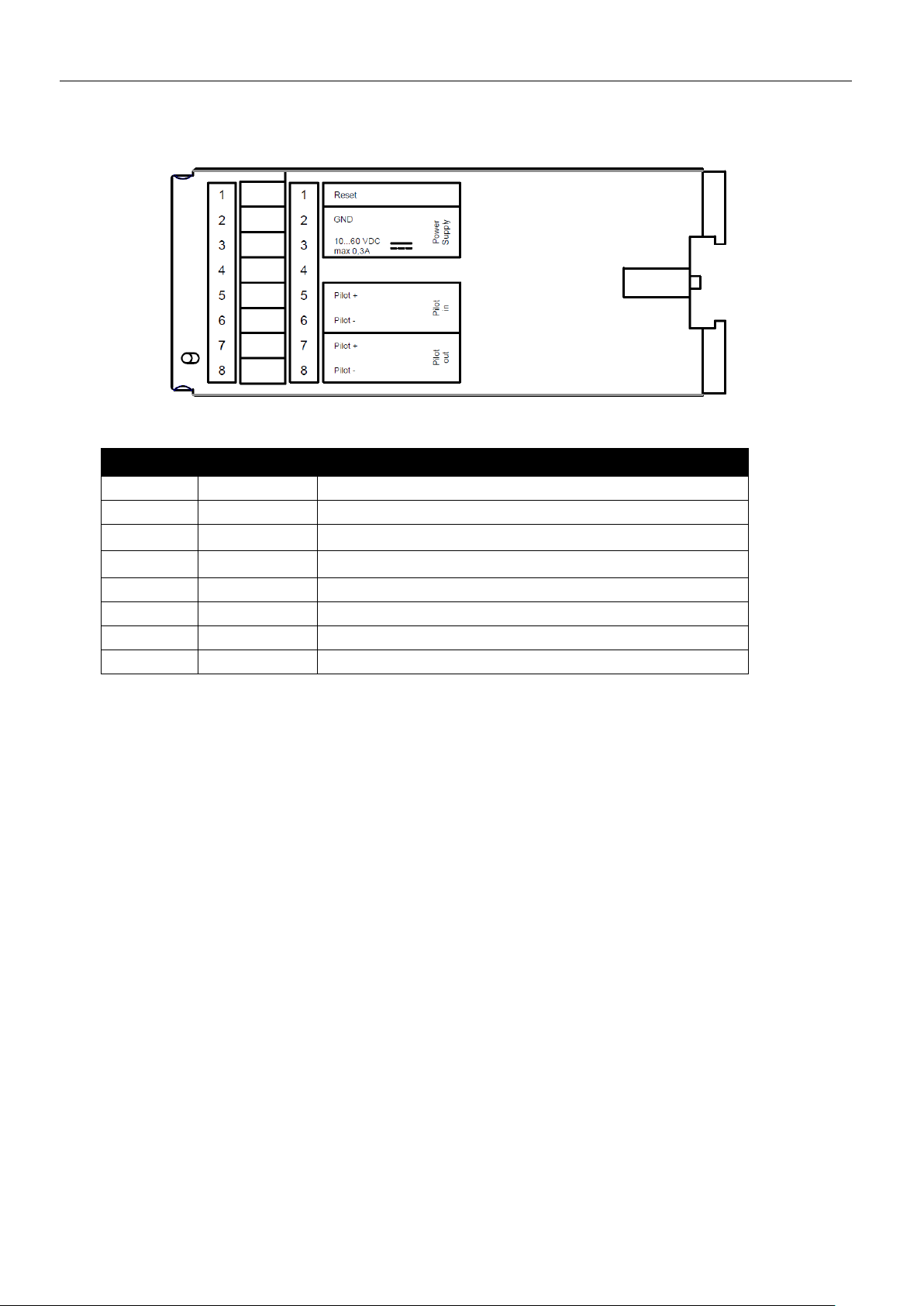
6.2 Terminal Connections on the Bottom
Figure 3: Connections on the bottom of the device
Terminal
Description
Description
1
Reset
Reset input
2
GND
Ground
3
10 ... 60 VDC
Power supply 10 V – 60 V DC
4
-
not connected
5
Pilot In +
Input signal pilot line from pilot source
6
Pilot In –
Input signal pilot line from pilot source
7
Pilot Out +
Output signal pilot line to charging socket
8
Pilot Out –
Output signal pilot line to charging socket
Table 6: Connections on the bottom of the device
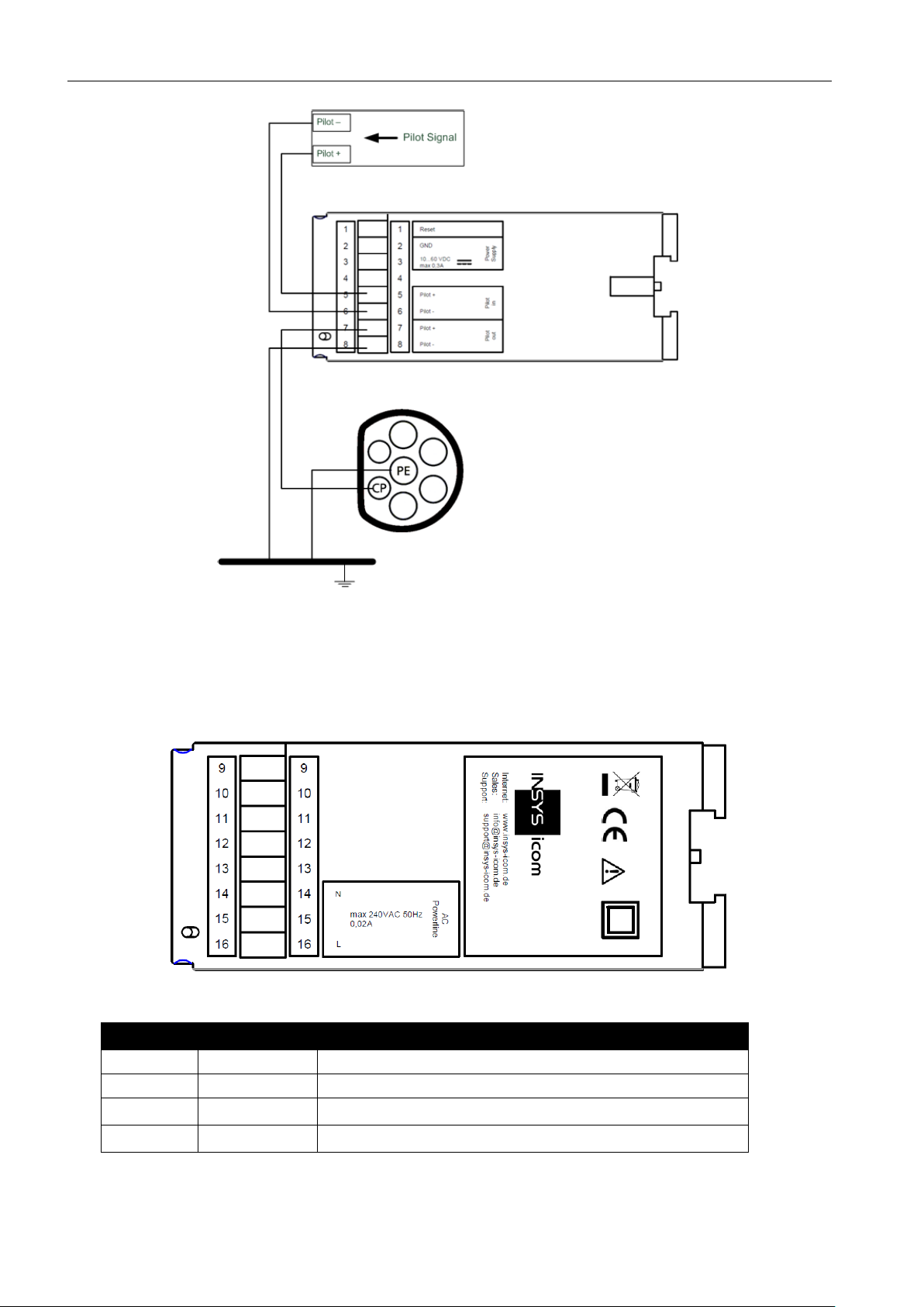
In order to minimise delays of the powerline signal, the connection
between PE and the negative pilot line signal should be made at the
charging socket, i.e. at the "Pilot Out" side. The two signals "Pilot In +"
and "Pilot In –" should be connected directly to the pilot signal source
without PE reference. See Figure 4.
Page 21
INSYS Powerline GP
Connections
21
Figure 4: Pilot signal connection
6.3 Terminal Connections on the Top
Figure 5: Connections on the top of the device
Terminal
Description
Description
9 – 13
-
not connected
14 N Powerline connection
15
-
not connected
16
L
Powerline connection
Table 7: Connections on the top of the device
Page 22

Function Overview
INSYS Powerline GP
22
7 Function Overview
Charging station (EVSE) and electric vehicle (PEV) communicate using the
powerline standard HomePlug GreenPHY™ 1.1 as per ISO/IEC 15118. The
requirements for this are described in ISO/IEC 15118-3. The INSYS Powerline GP
provides the communication connection between the EVSE controller (as per
ISO/IEC 15118-2) and the electric vehicle (PEV). The data stream will be modulated
to the pilot line of the charging cable or the power line as per ISO/IEC 15118-3
here.
The INSYS Powerline GP provides you with the following functions:
Communication via powerline standard HomePlug GreenPHY™
Coupling of the powerline signal to the pilot line
Coupling of the powerline signal to the power line
SLAC protocol as per ISO/IEC 15118-3
Page 23
INSYS Powerline GP
Assembly
23
8 Assembly
This chapter describes how to mount the INSYS Powerline GP to a DIN rail,
connect the power supply, connect the communication line and uninstall it
again. Observe the instructions in the "Safety" section of this manual, in
particular the "Safety Instructions for Electrical Installation" for that purpose
unconditionally.
Danger!
Exposed electrical components!
Risk of fatal injury from electric shock.
Prior to the installation, switch the power supply of the
cabinet off and secure it against being switched on again.
Danger!
Potentially lethal operating voltage!
Risk of death through shock hazard when touching it.
The INSYS Powerline GP is an electronic device, which
may only be used for fixed installation. The INSYS
Powerline GP must be installed that it cannot be touched
by the user after installation. An access to the installed
device may only be possible using tools, keys or removing
an internal cover. Moreover, a warning sign must be
attached, which warns against potentially tangible
energised components.
Danger!
Potentially lethal operating voltage!
Risk of death through shock hazard when touching it.
The power line used for communication must provide an
easily accessible, fixed installed cut-off device and a an
automatic cutout. The automatic cutout must be designed
for a maximum nominal current of 16A. The cut-off device
must be designed bipolar for ungrounded power supply
networks (e.g. IT network or DC supply without PE
reference).
Page 24

Assembly
INSYS Powerline GP
24
Warning!
Moisture and liquids from the environment may seep into
the interior of the INSYS Powerline GP!
Risk of fatal injury from electric shock when touching as
well as fire hazard and damage of the product.
The INSYS Powerline GP must not be used in wet or damp
environments, or in the direct vicinity of water. Install the
INSYS Powerline GP at a dry location, protected from
water spray. Disconnect the power supply before you
perform any work on a INSYS Powerline GP which may
have been in contact with moisture.
Warning!
Short-cuts and damage due to improper installation!
Fire, breakdown and risk of injury.
The INSYS Powerline GP should be handled with special
care like all electronic devices. Only a person, who is able
to work on electrical installations and identify and avoid
possible hazards independently, based on professional
training, knowledge and experience as well as knowledge
of the relevant standards and regulations is permitted to
install the device according to the generally known
engineering rules and the regulations, which are decisive
for building telecommunication devices or terminal
devices.
Caution!
The device could be destroyed if the wrong power supply
is used!
If the INSYS Powerline GP is operated with a power supply
that supplies a voltage exceeding the permissible
operating voltage of the INSYS Powerline GP, the device
will be destroyed.
Make sure that you use the suitable power supply. Refer to
the Technical Data section for the proper voltage range of
the INSYS Powerline GP.
Page 25

INSYS Powerline GP
Assembly
25
Caution!
Destruction of the device due to transport damage and
improper connection conditions!
If a INSYS Powerline GP with transport damage is used or
improper connection conditions are present, the device
will be destroyed.
Please check the device for visible transport damage as
well as the connection conditions at the site against the
requirements of the device before installation. The
connection may only be performed using proper tools and
must not be performed in energised condition.
Note
Radio interferences in short wave range!
The INSYS Powerline GP may interfere the reception of
short wave radio in the direct close range.
The INSYS Powerline GP can cause radio interferences in
the living quarters; in this case the operator can be
requested to take appropriate measures.
Mounting the device to the DIN rail
How to mount the INSYS Powerline GP to a DIN rail:
1. Position the device at the DIN rail as seen in the following diagram.
There are two snap-in hooks at the upper and lower edge of the DIN
rail groove of INSYS Powerline GP. Hook the upper one into place
behind the upper edge of the DIN rail.
Page 26

Assembly
INSYS Powerline GP
26
2. Lift the INSYS Powerline GP perpendicular to the DIN rail until the
two lower, flexible snap-in hooks engage in the DIN rail.
The INSYS Powerline GP is now readily mounted.
Connecting the power supply
The device has already been mounted to the DIN rail.
The power supply is connected and switched off.
1. Connect the ground lead of the power supply to the terminal "GND".
2. Connect the plus pole of the power supply to the terminal for the
power supply.
The INSYS Powerline GP is connected to the power supply now.
Connecting the pilot line
The device has already been mounted to the DIN rail.
The power supply is connected and switched off.
1. Connect the pilot signal source with the terminals 5 ("Pilot In –") and
6 ("Pilot In +").
2. Connect the charging socket with the terminals 7 ("Pilot Out –") and 8
("Pilot Out +").
"Pilot Out +" can be connected directly to the "CP" pin of the charging
socket and "Pilot Out –" with the PE connection of the charging
socket.
The INSYS Powerline GP is connected to the pilot line now.
Page 27

INSYS Powerline GP
Assembly
27
Disconnecting the pilot line
The device is mounted to the DIN rail.
The power supply is connected and switched off.
1. Disconnect the pilot signal source from the terminals 5 ("Pilot In –")
and 6 ("Pilot In +").
2. Disconnect the charging socket from the terminals 7 ("Pilot Out –")
and 8 ("Pilot Out +").
The INSYS Powerline GP is now disconnected from the pilot line.
Disconnecting the power supply
The device is mounted to the DIN rail.
The power supply is connected and switched off.
1. Disconnect the ground lead of the power supply from the terminal
"GND".
2. Disconnect the plus pole of the power supply from the terminal for
the power supply.
The INSYS Powerline GP is disconnected from the power supply.
Removing the device from the DIN rail
How to uninstall the INSYS Powerline GP from a DIN rail in a switch
cabinet:
You will need a Phillips screwdriver with a 4.5 mm blade.
The power supply of the switch cabinet is switched off and secured against
being switched on accidentally.
All cables at the INSYS Powerline GP are disconnected.
Danger!
Exposed electrical components!
Risk of fatal injury from electric shock.
Prior to the installation, switch the power supply of the
cabinet off and secure it against being switched on again.
Page 28

Assembly
INSYS Powerline GP
28
1. Insert the Philips screwdriver into the groove in the bottom of the
INSYS Powerline GP as shown in the following figure.
2. Turn the Philips screwdriver into the direction of the INSYS Powerline
GP as shown in the following figure.
The plastic spring of the snap-in hook is stretched.
3. While you hold the plastic spring apart with the lower snap-in hooks,
pull the INSYS Powerline GP away from the DIN rail.
4. Un-hook the INSYS Powerline GP and take it off perpendicularly to
the DIN rail.
The INSYS Powerline GP is now removed from the DIN rail.
Page 29

INSYS Powerline GP
Function
29
9 Function
The firmware update and the configuration under Windows require that the
"WinPcap" program library is installed on the computer used for this purpose. The
program library is freeware and available under www.winpcap.org.
9.1 Firmware Update
You'll get a description of the firmware update and the files necessary for this upon
request from support@insys-tec.de
If a different firmware than the one provided by INSYS is used or the firmware is
modified, any claims for warranty and support will cease to exist.
9.2 Configuration
The configuration of the INSYS Powerline GP can be done using two different tool
kits:
• devolo dLAN SDK under Windows
• open-plc-utils under Windows and Linux
Both options are described in the following. It must be observed that only commands approved by INSYS may be used for configuration. These are the commands described in the following. INSYS does not assume any liability for damages
caused by the use of other commands than the ones described here.
9.2.1 Configuration using devolo dLAN SDK
The configuration of the INSYS Powerline GP takes place on command line level via
editing the PIB file according to the following scheme:
1. Download PIB file from the device and store it locally
2. Enter new configuration into the PIB file
3. Upload PIB file to the device
4. Reset device to adopt the changes
When configuring several devices, the PIB file of the concerned device
must always be downloaded and uploaded again upon modification. It
is not permitted to use a PIB file of a different device.
It is recommended to make a backup copy of the current PIB file prior to any modifications.
The following files are necessary for the configuration of the INSYS Powerline GP
(available under www.insys-icom.com/software in the Powerline GP Tools):
Page 30

Function
INSYS Powerline GP
30
• Command line program dlancontrol_extended.exe
• Command line program cfgcontrol_extended.exe
• PIB file (will be downloaded from the device)
The following basic commands are available for the command line program:
• dlancontrol_extended device get_info -a <DestMAC> -n <NICMAC>
<DestMAC> = MAC address of the device (see identification plate or status
information)
<NICMAC> = MAC address of the network interface (can be read out using
command line program "getmac")
Reading out the status information of the device
• dlancontrol_extended config get -a <DestMAC> -n <NICMAC> -f <OldPIB>
<DestMAC> = MAC address of the device (see identification plate or status
information)
<NICMAC> = MAC addressof the network interface (can be read out using
command line program "getmac")
<OldPIB> = file name under which the current PIB file will be stored
Reading out the PIB file from the device
• dlancontrol_extended config set -a <DestMAC> -n <NICMAC> -f <NewPIB>
<DestMAC> = MAC address of the device (see identification plate or status
information)
<NICMAC> = MAC addressof the network interface (can be read out using
command line program "getmac")
<NewPIB> = file name of the modified PIB
Writing the PIB file to the device
• dlancontrol_extended device reset -a <DestMAC> -n <NICMAC>
<DestMAC> = MAC address of the device (see identification plate or status
information)
<NICMAC> = MAC address of the network interface (can be read out using
command line program "getmac")
Resetting the device
Proceed as follows to perform the respective procedures:
• Reading out the status information
How to read out the status information of a INSYS Powerline GP.
The MAC address of the device is known (here: 00:05:B6:01:2F:FC).
The MAC address of the interface to which the device is connected is
known (here: 00:1B:21:A0:90:E0).
1. Enter the command into the command line as follows.
C:\>dlancontrol_extended device get_info –a 00:05:B6:01:2F:FC –n
00:1B:21:A0:90:E0
The status information of the device will be shown.
Page 31

INSYS Powerline GP
Function
31
• Reading out the PIB file
How to read out the PIB file from a device and store it under the name
"old.pib".
The MAC address of the device is known (here: 00:05:B6:01:2F:FC).
The MAC address of the interface to which the device is connected is
known (here: 00:1B:21:A0:90:E0).
1. Enter the command into the command line as follows.
C:\>dlancontrol_extended config get –a 00:05:B6:01:2F:FC –n
00:1B:21:A0:90:E0 –f old.pib
The PIB file will be stored under the name specified.
• Writing the PIB file
How to upload the PIB file with the name "new.pib" to a device.
The MAC address of the device is known (here: 00:05:B6:01:2F:FC).
The MAC address of the interface to which the device is connected is
known (here: 00:1B:21:A0:90:E0).
1. Enter the command into the command line as follows.
C:\>dlancontrol_extended config set –a 00:05:B6:01:2F:FC –n
00:1B:21:A0:90:E0 –f new.pib
The PIB file will be uploaded to the device.
• Resetting the Device
How to reset an INSYS Powerline GP.
The MAC address of the device is known (here: 00:05:B6:01:2F:FC).
The MAC address of the interface to which the device is connected is
known (here: 00:1B:21:A0:90:E0).
1. Enter the command into the command line as follows.
C:\>dlancontrol_extended device reset –a 00:05:B6:01:2F:FC –n
00:1B:21:A0:90:E0
The device will be reset.
Page 32

Function
INSYS Powerline GP
32
9.2.2 Configuration using open-plc-utils
The configuration of the INSYS Powerline GP takes place on command line level via
editing the PIB file according to the following scheme:
1. Download PIB file from the device and store it locally
2. Enter new configuration into the PIB file
3. Upload PIB file to the device
4. Reset device to adopt the changes
When configuring several devices, the PIB file of the concerned device
must always be downloaded and uploaded again upon modification. It
is not permitted to use a PIB file of a different device.
It is recommended to make a backup copy of the current PIB file prior to any modifications.
The following files are necessary for the configuration of the INSYS Powerline GP
under Windows / Linux (available under www.insys-icom.com/software in the Powerline GP Tools or under https://github.com/qca/open-plc-utils):
• plctool.exe / plctool
• PIB file (will be downloaded from the device)
The following basic commands are available for the command line program:
• plctool -afI -i<NetworkInterface> <DestMAC>
<NetworkInterface> = Ethernet network interface of the connected device
<DestMAC> = MAC address of the device (see identification plate or status
information)
Reading out the status information of the device
• plctool -p <old.pib> -i<NetworkInterface> <DestMAC>
<NetworkInterface> = Ethernet network interface of the connected device
<DestMAC> = MAC address of the device (see identification plate or status
information)
<old.pib> = file name under which the current PIB file will be stored
Reading out the PIB file from the device
• plctool -P <new.pib> -i<NetworkInterface> <DestMAC>
<NetworkInterface> = Ethernet network interface of the connected device
<DestMAC> = MAC address of the device (see identification plate or status
information)
<new.pib> = file name of the modified PIB file
Writing the PIB file to the device
Proceed as follows to perform the respective procedures:
Page 33

INSYS Powerline GP
Function
33
• Reading out the status information
How to read out the status information of a INSYS Powerline GP.
The MAC address of the device is known (here: 00:05:B6:03:2E:DE).
The Ethernet network interface to which the device is connected is known
(here: 2). If it is not known, it can be worked out by trial and error.
1. Enter the command into the command line as follows.
C:\>plctool -afI –i2 00:05:B6:03:2E:DE
nic2 00:05:B6:03:2E:DE Fetch Device Attributes
nic2 00:05:B6:03:2E:DE QCA7000-MAC-QCA7000-1.1.0.727-02-20130826-FINAL (1mb)
nic2 00:05:B6:03:2E:DE Fetch NVRAM Configuration
nic2 00:05:B6:03:2E:DE TYPE=0x1520 (M25P16) PAGE=0x0100 (256) BLOCK=0x10000
(65536) SIZE=0x200000 (2097152)
PIB 0-0 8080 bytes
MAC 00:05:B6:03:2E:DE
DAK 92:C1:32:71:E4:B5:EC:68:2D:FB:BD:25:4E:A7:37:77
NMK 41:49:AD:59:AD:CB:7C:01:93:11:69:0E:64:8E:AC:65
NID 48:E0:F7:C5:53:7D:07
NET Qualcomm Atheros Enabled Network
MFG Qualcomm Atheros HomePlug AV Device
USR evse_pilot_3
CCo Always
MDU N/A
The status information of the device will be shown.
• Reading out the PIB file
How to read out the PIB file from a device and store it under the name
"old.pib".
The MAC address of the device is known (here: 00:05:B6:03:2E:DE).
The Ethernet network interface to which the device is connected is known
(here: 2).
1. Enter the command into the command line as follows.
C:\>plctool -p old.pib –i2 00:05:B6:03:2E:DE
nic2 00:05:B6:03:2E:DE Read Module from Memory
The PIB file will be stored under the name specified.
Page 34

Function
INSYS Powerline GP
34
• Writing the PIB file
How to upload the PIB file with the name "new.pib" to a device.
The MAC address of the device is known (here: 00:05:B6:03:2E:DE).
The Ethernet network interface to which the device is connected is known
(here: 2).
1. Enter the command into the command line as follows.
C:\>plctool -P new.pib –i2 00:05:B6:03:2E:DE
nic2 00:05:B6:03:2E:DE Start Module Write Session
nic2 00:05:B6:03:2E:DE Flash new.pib
...
The PIB file will be uploaded to the device.
Page 35

INSYS Powerline GP
Function
35
9.3 SLAC Protocol
The modem INSYS Powerline GP implements the SLAC protocol as per
ISO/IEC15118-3 for the charging station side (EVSE). Objective of the SLAC protocol is the association between PEV (Plug-In Electronic Vehicle) and EVSE. Upon
successful association, PEV and EVSE will establish an AVLN (AV Logical Network).
The easiest case for a successful procedure of the SLAC protocol would be as follows:
1. The modem is configured correctly and connected to a control pilot signal.
2. A PEV is also connected to the control pilot signal and sends SLAC parameter
-requests.
3. Send command HC_LISTEN_FOR_SLAC_ASSN.IND to the modem.
If the SLAC protocol has been executed successfully, this will be indicated by the
activation of the Link LED at the front.
The receipt of a validation request message from the PEV (BCB
Toggle) will always be answered by the modem with "not required".
Page 36

Function
INSYS Powerline GP
36
9.3.1 SLAC Interface
The INSYS Powerline GP is able to accept commands via the Ethernet interface.
Outgoing messages are also sent via the Ethernet interface. The recipient of outgoing messages will be referred to as Higher-level Entity (HLE) in the following.
9.3.1.1 Starting SLAC
The command HC_LISTEN_FOR_SLAC_ASSN.IND prepares the INSYS Powerline
GP for performing a SLAC association.
Figure 6: Sequence diagram: Starting SLAC
Page 37

INSYS Powerline GP
Function
37
9.3.1.2 Terminating SLAC
An existing connection can be terminated in the following ways.
The INSYS Powerline GP will cease to participate in any SLAC association and terminate a possibly existing connection with the command HC_STOP_LISTEN_FOR_SLAC_ASSN.IND.
Figure 7: Sequence diagram: Terminating SLAC with HC_STOP_LISTEN_FOR_SLAC_ASSN.IND
Page 38

Function
INSYS Powerline GP
38
The INSYS Powerline GP will cease to participate in any SLAC association and terminate a possibly existing connection with the command D_LINK_TERMINATE.request RESETUP no.
Figure 8: Sequence diagram: Terminating SLAC with D_LINK_TERMINATE.REQ Resetup no
Page 39

INSYS Powerline GP
Function
39
The INSYS Powerline GP will terminate a possibly existing connection and allow a
new SLAC association with the command D_LINK_TERMINATE.request RESETUP
yes.
Figure 9: Sequence diagram: Terminating SLAC with D_LINK_TERMINATE.REQ Resetup yes
Page 40

Function
INSYS Powerline GP
40
9.3.1.3 Status Messages
The following status messages are event-based and will be sent to the HLE upon
the respective event.
The INSYS Powerline GP will inform the HLE that it is ready to perform a SLAC association with the status message HC_STATUS.IND. Before a SLAC association can
be performed, it generates a random NMK (Network Membership Key) and thus
sets the access data for the next AVLN.
Figure 10: Sequence diagram: Status mes System_Ready
Page 41

INSYS Powerline GP
Function
41
The INSYS Powerline GP informs the HLE that no SLAC association has been
achieved with the status message Timeout_TT_EVSE_SLAC_init. It will not respond
on any SLAC requests following this timeout.
Figure 11: Sequence diagram: Status message Timeout_TT_EVSE_SLAC_init
Page 42

Function
INSYS Powerline GP
42
The INSYS Powerline GP will inform the HLE that it has sent an Attenuation Profile
to a PEV, but has not received an answer from it, with the status message
Timeout_TT_EVSE_match_session.
Figure 12: Sequence diagram: Status message Timeout_TT_EVSE_match_session
Page 43

INSYS Powerline GP
Function
43
The INSYS Powerline GP will inform the HLE that an association between PEV and
EVSE has been made, but no AVLN could be established, with the status message
Timeout_TT_EVSE_match_join.
Figure 13: Sequence diagram: Status message Timeout_TT_EVSE_match_join
Page 44

Function
INSYS Powerline GP
44
9.3.1.4 Status Request
The command HC_STATUS.REQ Req_DLinkStatus allows to check, whether an
AVLN exists between the INSYS Powerline GP and a PEV.
Figure 14: Sequence diagram: Status request HC_STATUS.REQ
Page 45

INSYS Powerline GP
Function
45
9.3.2 Commands
The commands are transmitted in basic Ethernet frames as per IEEE 802.3 and are
structured as follows.
9.3.2.1 HC_LISTEN_FOR_SLAC_ASSN
Set System State to Unmatched. The device will listen for SLAC requests.
Prerequisite: System State is Unoccupied
Field
Field size
(octets)
Definition
Dest. MAC
6
Powerline GP MAC
Source MAC
6
HLE MAC
Ethertype
2
Ethertype = 0xabba
Reserved
1
Reserved = 0x00
Type
2
HC_LISTEN_FOR_SLAC_ASSN.IND Type = 0x0b01
AttenRxEVSE
58
Rx attenuation of the charging station (see AttenRxEVSE)
Table 8: HC_LISTEN_FOR_SLAC_ASSN.IND message
Confirmation of HC_LISTEN_FOR_SLAC_ASSN.IND.
Result is a failure if System State is not Unoccupied.
Field
Field size
(octets)
Definition
Dest. MAC
6
Source MAC of HC_LISTEN_FOR_SLAC_ASSN.IND
Source MAC
6
Powerline GP MAC
Ethertype
2
Ethertype = 0xabba
Reserved
1
Reserved = 0x00
Type
2
HC_LISTEN_FOR_SLAC_ASSN.CNF Type = 0x0b02
Result
1
Result of HC_LISTEN_FOR_SLAC_ASSN.IND.
0x00 = failure, 0x01 = success
Table 9: HC_LISTEN_FOR_SLAC_ASSN.CNF message
Page 46

Function
INSYS Powerline GP
46
9.3.2.2 HC_STOP_LISTEN_FOR_SLAC_ASSN
Set System State to Unoccupied and stop all possible running Associations.
Prerequisite: System State shall not be Unoccupied
Field
Field size
(octets)
Definition
Dest. MAC
6
Powerline GP MAC
Source MAC
6
HLE MAC
Ethertype
2
Ethertype = 0xabba
Reserved
1
Reserved = 0x00
Type
2
HC_STOP_LISTEN_FOR_SLAC_ASSN.IND Type = 0x0b03
Reserved
1
Reserved = 0x00
Table 10: HC_STOP_LISTEN_FOR_SLAC_ASSN.IND message
Confirmation of HC_STOP_LISTEN_FOR_SLAC_ASSN.IND.
Result is a failure if System State is already Unoccupied.
Field
Field size
(octets)
Definition
Dest. MAC
6
Source MAC of HC_STOP_LISTEN_FOR_SLAC_ASSN.IND
Source MAC
6
Powerline GP MAC
Ethertype
2
Ethertype = 0xabba
Reserved
1
Reserved = 0x00
Type
2
HC_STOP_LISTEN_FOR_SLAC_ASSN.CNF Type = 0x0b04
Result
1
Result of HC_STOP_LISTEN_FOR_SLAC_ASSN.IND.
0x00 = failure, 0x01 = success,
0x02 = System State is already Unoccupied
Table 11: HC_STOP_LISTEN_FOR_SLAC_ASSN.CNF message
Page 47

INSYS Powerline GP
Function
47
9.3.2.3 HC_ATTEN_CALC_RESULT
Status message that includes an Attenuation Profile. Every time the device sends
an Attenuation Profile to a PEV, the same profile will also be sent to the HLE.
Field
Field size
(octets)
Definition
Dest. MAC
6
HLE MAC
Source MAC
6
Powerline GP MAC
Ethertype
2
Ethertype = 0xabba
Reserved
1
Reserved = 0x00
Type
2
HC_ATTEN_CALC_RESULT.IND Type = 0x0b05
EV MAC
6
EV MAC
RUN ID
8
RUN ID
M-Sound
1
Number of M-Sound messages used for the calculation of the Attenuation Profile
Attn
58
Attenuation Profile
Table 12: HC_ATTEN_CALC_RESULT.IND message
9.3.2.4 D_LINK_READY
Status message that indicates a succssfully completed SLAC Association.
Field
Field size
(octets)
Definition
Dest. MAC
6
HLE MAC
Source MAC
6
Powerline GP MAC
Ethertype
2
Ethertype = 0xabba
Reserved
1
Reserved = 0x00
Type
2
D_LINK_READY.IND Type = 0x0b06
Result
1
Result of D_LINK_READY.IND
0x00 = link established, 0x01 = no link
Table 13: D_LINK_READY.IND message
Page 48

Function
INSYS Powerline GP
48
9.3.2.5 D_LINK_TERMINATE
Terminates a current SLAC Association. If Resetup is yes, the device will listen
again for SLAC requests. If Resetup is no, the device will remain in Unmatched
state.
Prerequisite: System State is Matched or Unmatched
Field
Field size
(octets)
Definition
Dest. MAC
6
Powerline GP MAC
Source MAC
6
HLE MAC
Ethertype
2
Ethertype = 0xabba
Reserved
1
Reserved = 0x00
Type
2
D_LINK_TERMINATE.REQ Type = 0x0b07
Request
1
0x00 = Resetup yes, 0x01 = Resetup no
AttenRxEVSE
58
Rx attenuation of the charging station (see AttenRxEVSE)
Table 14: D_LINK_TERMINATE.REQ message
Confirmation of D_LINK_TERMINATE.REQ
Result is a failure if System State is Unoccupied.
Field
Field size
(octets)
Definition
Dest. MAC
6
HLE MAC
Source MAC
6
Powerline GP MAC
Ethertype
2
Ethertype = 0xabba
Reserved
1
Reserved = 0x00
Type
2
D_LINK_TERMINATE.CNF Type = 0x0b08
Previous req.
1
Request type of the previously received HC_ATTEN_CALC_RESULT.IND message
0x00 = Resetup yes, 0x01 = Resetup no
Status
1
0x00 = failure, 0x01 = success
Table 15: D_LINK_TERMINATE.CNF message
Page 49

INSYS Powerline GP
Function
49
9.3.2.6 HC_STATUS Indication
Indicates several Status Information.
Field
Field size
(octets)
Definition
Dest. MAC
6
HLE MAC
Source MAC
6
Powerline GP MAC
Ethertype
2
Ethertype = 0xabba
Reserved
1
Reserved = 0x00
Type
2
HC_STATUS.IND Type = 0x0b09
HC_Status
type
1
0x00 = Timeout_TT_EVSE_SLAC_init
0x01 = System_Ready
0x02 = Timeout_TT_EVSE_match_MNBC
0x03 = Timeout_TT_EVSE_match_session
0x04 = Timeout_TT_match_join
0x05 = Timeout_TT_match_sequence
0x06 = Timeout_TT_match_response
0x07 = System_init_Failed
Table 16: HC_STATUS.IND message
9.3.2.7 HC_STATUS Request
Requests a Status Information from the device:
Field
Field size
(octets)
Definition
Dest. MAC
6
Powerline GP MAC
Source MAC
6
HLE MAC
Ethertype
2
Ethertype = 0xabba
Reserved
1
Reserved = 0x00
Type
2
HC_STATUS.REQ Type = 0x0b0a
Request
1
0x00 = Req_DLinkStatus
Table 17: HC_STATUS.REQ message
Page 50

Function
INSYS Powerline GP
50
Confirmation of HC_STATUS.REQ
Status Information from the device
Field
Field size
(octets)
Definition
Dest. MAC
6
Source MAC of HC_STATUS.REQ
Source MAC
6
Powerline GP MAC
Ethertype
2
Ethertype = 0xabba
Reserved
1
Reserved = 0x00
Type
2
HC_STATUS.CNF Type = 0x0b0b
Previous req.
1
Request type of the previously received HC_STATUS.REQ message
0x00 = Req_DLinkStatus
Req. status
1
Number of GreenPHY stations in the AVLN
0x00 = no link with PEV, 0x01 = existing link with one PEV
Table 18: HC_STATUS.CNF message
Page 51

INSYS Powerline GP
Function
51
9.3.2.8 AttenRxEVSE
This value stands for the attenuation in the charging station between the charging
coupling and the Pilot-Out of the INSYS Powerline GP (without charging cable). AttenRxEVSE has the same format as an Attenuation Profile, which is described in
the Homeplug GreenPHY specification 1.1 (ATTEN_PROFILE).
The Attenuation Profile computed during the SLAC protocol will be corrected by
this value. This ensures that the PEV gets a correct attenuation value.
EVSE
INSYS
Powerline
GP Modem
ISO15118-3
Pilot out
LAN
Charging station
AttnRxEVSE
Figure 15: AttenRxEVSE
Page 52

Maintenance, Repair and Troubleshooting
INSYS Powerline GP
52
10 Maintenance, Repair and Troubleshooting
10.1 Maintenance
The product is maintenance-free and does not require special regular maintenance.
10.2 Troubleshooting
If a failure occurs during the operation of the product, you will find troubleshooting
tips in the "Knowledge Base" on our web site (http://www.insysicom.de/knowledge/). If you need further support, please contact your reseller or
INSYS icom. You can contact our support team via e-mail under support@insystec.de.
10.3 Repair
Send defect devices with detailed failure description to the source of supply of your
device. If you have purchased the device directly from INSYS icom, send the device
to: INSYS MICROELECTRONICS GmbH, Hermann-Köhl-Str. 22, 93049 Regensburg.
Before dispatching the device:
• Remove any inserted SIM cards.
• Backup the configuration on the device and any other stored data if required.
• Backup any sandbox applications running on the device.
Caution!
Short circuits and damage due to improper repairs and
modifications as well as opening of products.
Fire hazard and damage of the product.
It is not permitted to open the product for repair or
modification.
Page 53

INSYS Powerline GP
Waste Disposal
53
11 Waste Disposal
11.1 Repurchasing of Legacy Systems
According to the new WEEE guidelines, the repurchasing and recycling of legacy
systems for our clients is regulated as follows:
Please send those legacy systems to the following address, carriage prepaid:
Frankenberg-Metalle
Gaertnersleite 8
D-96450 Coburg
Germany
This regulation applies to all devices which were delivered after August 13, 2005.
Please consider possible stored passwords or security certificates
before disposing the device. It is recommended to block possible
existing access rights for the device (e.g. on your VPN server) and
reset the device to default settings (if possible), before passing it on or
disposing it.
Page 54

Declaration of Conformity
INSYS Powerline GP
54
12 Declaration of Conformity
This device complies with the requirements set out in the Council Directive on the
Approximation of the Laws of the Member States relating to Electromagnetic Compatibility 2004/108/EC and the Council Directive relating to Low Voltage
2006/95/EC.
The equipment is in conformity with Directive 2011/65/EU of the European Parliament and of the Council of 8 June 2011 on the restriction of the use of certain hazardous substances in electrical and electronic equipment.
You will find the latest Declaration of Conformity for this product on the enclosed
Support CD in the documentation section. We will gladly send you a copy of the
Declaration of Conformity on request as well
Page 55

INSYS Powerline GP
Licenses
55
13 Licenses
The source code of the firmware of this device is covered by various licenses.
FreeRTOS
The FreeRTOS.org source code is licensed by the modified GNU General Public License (GPL) text provided below. The FreeRTOS download also includes demo application source code, some of which is provided by third parties
AND IS LICENSED SEPARATELY FROM FREERTOS.ORG.
For the avoidance of any doubt refer to the comment included at the top of each
source and header file for license and copyright information.
This is a list of files for which Real Time Engineers Ltd are not the copyright owner
and are NOT COVERED BY THE GPL.
1) Various header files provided by silicon manufacturers and tool vendors that define processor specific memory addresses and utility macros. Permission has
been granted by the various copyright holders for these files to be included in
the FreeRTOS download. Users must ensure license conditions are adhered to
for any use other than compilation of the FreeRTOS demo applications.
2) The uIP TCP/IP stack the copyright of which is held by Adam Dunkels. Users
must ensure the open source license conditions stated at the top of each uIP
source file is understood and adhered to.
3) The lwIP TCP/IP stack the copyright of which is held by the Swedish Institute of
Computer Science. Users must ensure the open source license conditions
stated at the top of each lwIP source file is understood and adhered to.
4) Various peripheral driver source files and binaries provided by silicon manufacturers and tool vendors. Permission has been granted by the various copyright
holders for these files to be included in the FreeRTOS download. Users must ensure license conditions are adhered to for any use other than compilation of the
FreeRTOS demo applications.
5) The files contained within FreeRTOS\Demo\WizNET_DEMO_TERN_186\tern_code, which are slightly modified
versions of code provided by and copyright to Tern Inc.
Errors and omissions should be reported to Richard Barry, contact details for whom
can be obtained from http://www.FreeRTOS.org.
The GPL license text follows.
A special exception to the GPL is included to allow you to distribute a combined
work that includes FreeRTOS without being obliged to provide the source code for
any proprietary components. See the licensing section of http://www.FreeRTOS.org
for full details. The exception text is also included at the bottom of this file.
Page 56

Licenses
INSYS Powerline GP
56
GNU GENERAL PUBLIC LICENSE
TERMS AND CONDITIONS FOR COPYING, DISTRIBUTION AND MODIFICATION
0. This License applies to any program or other work which contains a notice
placed by the copyright holder saying it may be distributed under the terms of
this General Public License. The "Program", below, refers to any such program
or work, and a "work based on the Program" means either the Program or any
derivative work under copyright law: that is to say, a work containing the Program or a portion of it, either verbatim or with modifications and/or translated
into another language. (Hereinafter, translation is included without limitation in
the term "modification".) Each licensee is addressed as "you".
Activities other than copying, distribution and modification are not covered by
this License; they are outside its scope. The act of running the Program is not
restricted, and the output from the Program is covered only if its contents constitute a work based on the Program (independent of having been made by running the Program). Whether that is true depends on what the Program does.
1. You may copy and distribute verbatim copies of the Program's source code as
you receive it, in any medium, provided that you conspicuously and appropriately publish on each copy an appropriate copyright notice and disclaimer of
warranty; keep intact all the notices that refer to this License and to the absence
of any warranty; and give any other recipients of the Program a copy of this License along with the Program.
You may charge a fee for the physical act of transferring a copy, and you may at
your option offer warranty protection in exchange for a fee.
2. You may modify your copy or copies of the Program or any portion of it, thus
forming a work based on the Program, and copy and distribute such modifications or work under the terms of Section 1 above, provided that you also meet
all of these conditions:
a) You must cause the modified files to carry prominent notices stating that
you changed the files and the date of any change.
b) You must cause any work that you distribute or publish, that in whole or in
part contains or is derived from the Program or any part thereof, to be licensed as a whole at no charge to all third parties under the terms of this License.
c) If the modified program normally reads commands interactively when run,
you must cause it, when started running for such interactive use in the most
ordinary way, to print or display an announcement including an appropriate
copyright notice and a notice that there is no warranty (or else, saying that
you provide a warranty) and that users may redistribute the program under
these conditions, and telling the user how to view a copy of this License.
(Exception: if the Program itself is interactive but does not normally print
Page 57

INSYS Powerline GP
Licenses
57
such an announcement, your work based on the Program is not required to
print an announcement.)
These requirements apply to the modified work as a whole. If identifiable sections of that work are not derived from the Program, and can be reasonably
considered independent and separate works in themselves, then this License,
and its terms, do not apply to those sections when you distribute them as separate works. But when you distribute the same sections as part of a whole which
is a work based on the Program, the distribution of the whole must be on the
terms of this License, whose permissions for other licensees extend to the entire whole, and thus to each and every part regardless of who wrote it.
Thus, it is not the intent of this section to claim rights or contest your rights to
work written entirely by you; rather, the intent is to exercise the right to control
the distribution of derivative or collective works based on the Program.
In addition, mere aggregation of another work not based on the Program with
the Program (or with a work based on the Program) on a volume of a storage or
distribution medium does not bring the other work under the scope of this License.
3. You may copy and distribute the Program (or a work based on it, under Section 2) in object code or executable form under the terms of Sections 1 and 2
above provided that you also do one of the following:
a) Accompany it with the complete corresponding machine-readable source
code, which must be distributed under the terms of Sections 1 and 2 above
on a medium customarily used for software interchange; or,
b) Accompany it with a written offer, valid for at least three years, to give any
third party, for a charge no more than your cost of physically performing
source distribution, a complete machine-readable copy of the corresponding
source code, to be distributed under the terms of Sections 1 and 2 above on
a medium customarily used for software interchange; or,
c) Accompany it with the information you received as to the offer to distribute
corresponding source code. (This alternative is allowed only for noncommercial distribution and only if you received the program in object code or executable form with such an offer, in accord with Subsection b above.)
The source code for a work means the preferred form of the work for making
modifications to it. For an executable work, complete source code means all the
source code for all modules it contains, plus any associated interface definition
files, plus the scripts used to control compilation and installation of the executable. However, as a special exception, the source code distributed need not include anything that is normally distributed (in either source or binary form) with
the major components (compiler, kernel, and so on) of the operating system on
Page 58

Licenses
INSYS Powerline GP
58
which the executable runs, unless that component itself accompanies the executable.
If distribution of executable or object code is made by offering access to copy
from a designated place, then offering equivalent access to copy the source
code from the same place counts as distribution of the source code, even
though third parties are not compelled to copy the source along with the object
code.
4. You may not copy, modify, sublicense, or distribute the Program except as expressly provided under this License. Any attempt otherwise to copy, modify,
sublicense or distribute the Program is void, and will automatically terminate
your rights under this License. However, parties who have received copies, or
rights, from you under this License will not have their licenses terminated so
long as such parties remain in full compliance.
5. You are not required to accept this License, since you have not signed it. However, nothing else grants you permission to modify or distribute the Program or
its derivative works. These actions are prohibited by law if you do not accept
this License. Therefore, by modifying or distributing the Program (or any work
based on the Program), you indicate your acceptance of this License to do so,
and all its terms and conditions for copying, distributing or modifying the Program or works based on it.
6. Each time you redistribute the Program (or any work based on the Program), the
recipient automatically receives a license from the original licensor to copy, distribute or modify the Program subject to these terms and conditions. You may
not impose any further restrictions on the recipients' exercise of the rights
granted herein. You are not responsible for enforcing compliance by third parties to this License.
7. If, as a consequence of a court judgment or allegation of patent infringement or
for any other reason (not limited to patent issues), conditions are imposed on
you (whether by court order, agreement or otherwise) that contradict the conditions of this License, they do not excuse you from the conditions of this License. If you cannot distribute so as to satisfy simultaneously your obligations
under this License and any other pertinent obligations, then as a consequence
you may not distribute the Program at all. For example, if a patent license would
not permit royalty-free redistribution of the Program by all those who receive
copies directly or indirectly through you, then the only way you could satisfy
both it and this License would be to refrain entirely from distribution of the Program.
If any portion of this section is held invalid or unenforceable under any particular
circumstance, the balance of the section is intended to apply and the section as
a whole is intended to apply in other circumstances.
Page 59

INSYS Powerline GP
Licenses
59
It is not the purpose of this section to induce you to infringe any patents or
other property right claims or to contest validity of any such claims; this section
has the sole purpose of protecting the integrity of the free software distribution
system, which is implemented by public license practices. Many people have
made generous contributions to the wide range of software distributed through
that system in reliance on consistent application of that system; it is up to the
author/donor to decide if he or she is willing to distribute software through any
other system and a licensee cannot impose that choice.
This section is intended to make thoroughly clear what is believed to be a consequence of the rest of this License.
8. If the distribution and/or use of the Program is restricted in certain countries either by patents or by copyrighted interfaces, the original copyright holder who
places the Program under this License may add an explicit geographical distribution limitation excluding those countries, so that distribution is permitted only
in or among countries not thus excluded. In such case, this License incorporates
the limitation as if written in the body of this License.
9. The Free Software Foundation may publish revised and/or new versions of the
General Public License from time to time. Such new versions will be similar in
spirit to the present version, but may differ in detail to address new problems or
concerns.
Each version is given a distinguishing version number. If the Program specifies
a version number of this License which applies to it and "any later version", you
have the option of following the terms and conditions either of that version or of
any later version published by the Free Software Foundation. If the Program
does not specify a version number of this License, you may choose any version
ever published by the Free Software Foundation.
10. If you wish to incorporate parts of the Program into other free programs whose
distribution conditions are different, write to the author to ask for permission.
For software which is copyrighted by the Free Software Foundation, write to the
Free Software Foundation; we sometimes make exceptions for this. Our decision will be guided by the two goals of preserving the free status of all derivatives of our free software and of promoting the sharing and reuse of software
generally.
Page 60

Licenses
INSYS Powerline GP
60
NO WARRANTY
11. BECAUSE THE PROGRAM IS LICENSED FREE OF CHARGE, THERE IS NO
WARRANTY FOR THE PROGRAM, TO THE EXTENT PERMITTED BY APPLICABLE LAW. EXCEPT WHEN OTHERWISE STATED IN WRITING THE COPYRIGHT
HOLDERS AND/OR OTHER PARTIES PROVIDE THE PROGRAM "AS IS" WITHOUT WARRANTY OF ANY KIND, EITHER EXPRESSED OR IMPLIED, INCLUDING, BUT NOT LIMITED TO, THE IMPLIED WARRANTIES OF MERCHANTABILITY AND FITNESS FOR A PARTICULAR PURPOSE. THE ENTIRE RISK AS TO
THE QUALITY AND PERFORMANCE OF THE PROGRAM IS WITH YOU.
SHOULD THE PROGRAM PROVE DEFECTIVE, YOU ASSUME THE COST OF
ALL NECESSARY SERVICING, REPAIR OR CORRECTION.
12. IN NO EVENT UNLESS REQUIRED BY APPLICABLE LAW OR AGREED TO IN
WRITING WILL ANY COPYRIGHT HOLDER, OR ANY OTHER PARTY WHO MAY
MODIFY AND/OR REDISTRIBUTE THE PROGRAM AS PERMITTED ABOVE, BE
LIABLE TO YOU FOR DAMAGES, INCLUDING ANY GENERAL, SPECIAL, INCIDENTAL OR CONSEQUENTIAL DAMAGES ARISING OUT OF THE USE OR INABILITY TO USE THE PROGRAM (INCLUDING BUT NOT LIMITED TO LOSS OF
DATA OR DATA BEING RENDERED INACCURATE OR LOSSES SUSTAINED BY
YOU OR THIRD PARTIES OR A FAILURE OF THE PROGRAM TO OPERATE
WITH ANY OTHER PROGRAMS), EVEN IF SUCH HOLDER OR OTHER PARTY
HAS BEEN ADVISED OF THE POSSIBILITY OF SUCH DAMAGES.
END OF TERMS AND CONDITIONS
How to Apply These Terms to Your New Programs
If you develop a new program, and you want it to be of the greatest possible use to
the public, the best way to achieve this is to make it free software which everyone
can redistribute and change under these terms.
To do so, attach the following notices to the program. It is safest to attach them to
the start of each source file to most effectively convey the exclusion of warranty;
and each file should have at least the "copyright" line and a pointer to where the
full notice is found.
one line to give the program's name and an idea of what it does.
Copyright (C) yyyy name of author
This program is free software; you can redistribute it and/or
modify it under the terms of the GNU General Public License as
published by the Free Software Foundation; either version 2 of
the License, or (at your option) any later version.
Page 61

INSYS Powerline GP
Licenses
61
This program is distributed in the hope that it will be useful,
but WITHOUT ANY WARRANTY; without even the implied warranty of
MERCHANTABILITY or FITNESS FOR A PARTICULAR PURPOSE. See the GNU
General Public License for more details.
You should have received a copy of the GNU General Public License along with this program; if not, write to the Free Software Foundation, Inc., 51 Franklin Street, Fifth Floor, Boston,
MA 02110-1301, USA.
Also add information on how to contact you by electronic and paper mail.
If the program is interactive, make it output a short notice like this when it starts in
an interactive mode:
Gnomovision version 69, Copyright (C) year name of author Gnomovision comes with ABSOLUTELY NO WARRANTY; for details type
`show w'. This is free software, and you are welcome to redistribute it under certain conditions; type `show c' for details.
The hypothetical commands `show w' and `show c' should show the appropriate
parts of the General Public License. Of course, the commands you use may be
called something other than `show w' and `show c'; they could even be mouseclicks or menu items--whatever suits your program.
You should also get your employer (if you work as a programmer) or your school, if
any, to sign a "copyright disclaimer" for the program, if necessary. Here is a sample; alter the names:
Yoyodyne, Inc., hereby disclaims all copyright interest in the
program `Gnomovision' (which makes passes at compilers) written
by James Hacker.
signature of Ty Coon, 1 April 1989
Ty Coon, President of Vice
This General Public License does not permit incorporating your program into proprietary programs. If your program is a subroutine library, you may consider it more
useful to permit linking proprietary applications with the library. If this is what you
want to do, use the GNU Lesser General Public License instead of this License
Page 62

Licenses
INSYS Powerline GP
62
The FreeRTOS GPL Exception Text:
Any FreeRTOS source code, whether modified or in it's original release form, or
whether in whole or in part, can only be distributed by you under the terms of the
GNU General Public License plus this exception. An independent module is a module which is not derived from or based on FreeRTOS.
Clause 1:
Linking FreeRTOS statically or dynamically with other modules is making a com-
bined work based on FreeRTOS. Thus, the terms and conditions of the GNU General Public License cover the whole combination.
As a special exception, the copyright holder of FreeRTOS gives you permission to
link FreeRTOS with independent modules that communicate with FreeRTOS solely
through the FreeRTOS API interface, regardless of the license terms of these independent modules, and to copy and distribute the resulting combined work under
terms of your choice, provided that
• Every copy of the combined work is accompanied by a written statement
that details to the recipient the version of FreeRTOS used and an offer by
yourself to provide the FreeRTOS source code (including any modifications
you may have made) should the recipient request it.
• The combined work is not itself an RTOS, scheduler, kernel or related
product.
• The independent modules add significant and primary functionality to
FreeRTOS and do not merely extend the existing functionality already
present in FreeRTOS.
Clause 2:
FreeRTOS may not be used for any competitive or comparative purpose, including
the publication of any form of run time or compile time metric, without the express
permission of Real Time Engineers Ltd. (this is the norm within the industry and is
intended to ensure information accuracy).
Page 63

INSYS Powerline GP
Licenses
63
Swedish Institute of Computer Science
/*
* Copyright (c) 2001, Swedish Institute of Computer Science.
* All rights reserved.
*
* Redistribution and use in source and binary forms, with or without
* modification, are permitted provided that the following conditions
* are met:
* 1. Redistributions of source code must retain the above copyright
* notice, this list of conditions and the following disclaimer.
* 2. Redistributions in binary form must reproduce the above copyright
* notice, this list of conditions and the following disclaimer in the
* documentation and/or other materials provided with the distribution.
* 3. Neither the name of the Institute nor the names of its contributors
* may be used to endorse or promote products derived from this software
* without specific prior written permission.
*
* THIS SOFTWARE IS PROVIDED BY THE INSTITUTE AND CONTRIBUTORS ``AS IS'' AND
* ANY EXPRESS OR IMPLIED WARRANTIES, INCLUDING, BUT NOT LIMITED TO, THE
* IMPLIED WARRANTIES OF MERCHANTABILITY AND FITNESS FOR A PARTICULAR PURPOSE
* ARE DISCLAIMED. IN NO EVENT SHALL THE INSTITUTE OR CONTRIBUTORS BE LIABLE
* FOR ANY DIRECT, INDIRECT, INCIDENTAL, SPECIAL, EXEMPLARY, OR CONSEQUENTIAL
* DAMAGES (INCLUDING, BUT NOT LIMITED TO, PROCUREMENT OF SUBSTITUTE GOODS
* OR SERVICES; LOSS OF USE, DATA, OR PROFITS; OR BUSINESS INTERRUPTION)
* HOWEVER CAUSED AND ON ANY THEORY OF LIABILITY, WHETHER IN CONTRACT, STRICT
* LIABILITY, OR TORT (INCLUDING NEGLIGENCE OR OTHERWISE) ARISING IN ANY WAY
* OUT OF THE USE OF THIS SOFTWARE, EVEN IF ADVISED OF THE POSSIBILITY OF
* SUCH DAMAGE.
*
* This file is part of the lwIP TCP/IP stack.
*
* Author: Adam Dunkels <adam@sics.se>
*
*/
Page 64

Licenses
INSYS Powerline GP
64
Adam Dunkels
/*
* Copyright (c) 2001-2003, Adam Dunkels.
* All rights reserved.
*
* Redistribution and use in source and binary forms, with or without
* modification, are permitted provided that the following conditions
* are met:
* 1. Redistributions of source code must retain the above copyright
* notice, this list of conditions and the following disclaimer.
* 2. Redistributions in binary form must reproduce the above copyright
* notice, this list of conditions and the following disclaimer in the
* documentation and/or other materials provided with the distribution.
* 3. The name of the author may not be used to endorse or promote
* products derived from this software without specific prior
* written permission.
*
* THIS SOFTWARE IS PROVIDED BY THE AUTHOR ``AS IS'' AND ANY EXPRESS
* OR IMPLIED WARRANTIES, INCLUDING, BUT NOT LIMITED TO, THE IMPLIED
* WARRANTIES OF MERCHANTABILITY AND FITNESS FOR A PARTICULAR PURPOSE
* ARE DISCLAIMED. IN NO EVENT SHALL THE AUTHOR BE LIABLE FOR ANY
* DIRECT, INDIRECT, INCIDENTAL, SPECIAL, EXEMPLARY, OR CONSEQUENTIAL
* DAMAGES (INCLUDING, BUT NOT LIMITED TO, PROCUREMENT OF SUBSTITUTE
* GOODS OR SERVICES; LOSS OF USE, DATA, OR PROFITS; OR BUSINESS
* INTERRUPTION) HOWEVER CAUSED AND ON ANY THEORY OF LIABILITY,
* WHETHER IN CONTRACT, STRICT LIABILITY, OR TORT (INCLUDING
* NEGLIGENCE OR OTHERWISE) ARISING IN ANY WAY OUT OF THE USE OF THIS
* SOFTWARE, EVEN IF ADVISED OF THE POSSIBILITY OF SUCH DAMAGE.
*
* This file is part of the uIP TCP/IP stack.
*
*/
Page 65

INSYS Powerline GP
Licenses
65
devolo AG
/*
* Copyright (c) 2012, devolo AG, Aachen, Germany.
* All rights reserved.
*
* This Software is part of the devolo GreenPHY-SDK.
*
* Usage in source form and redistribution in binary form, with or without
* modification, are permitted provided that the following conditions
* are met:
* 1. Usage in source form is subject to a current end user license agreement
* with the devolo AG.
* 2. Neither the name of the devolo AG nor the names of its contributors
* may be used to endorse or promote products derived from this software
* without specific prior written permission.
* 3. Redistribution in binary form is limited to the usage on the GreenPHY
* module of the devolo AG.
* 4. Redistribution in binary form must reproduce the above copyright
* notice, this list of conditions and the following disclaimer in the
* documentation and/or other materials provided with the distribution.
*
* THIS SOFTWARE IS PROVIDED BY THE COPYRIGHT HOLDERS AND CONTRIBUTORS "AS IS"
* AND ANY EXPRESS OR IMPLIED WARRANTIES, INCLUDING, BUT NOT LIMITED TO, THE
* IMPLIED WARRANTIES OF MERCHANTABILITY AND FITNESS FOR A PARTICULAR PURPOSE
* ARE DISCLAIMED. IN NO EVENT SHALL THE COPYRIGHT HOLDER OR CONTRIBUTORS BE
* LIABLE FOR ANY DIRECT, INDIRECT, INCIDENTAL, SPECIAL, EXEMPLARY, OR
* CONSEQUENTIAL DAMAGES (INCLUDING, BUT NOT LIMITED TO, PROCUREMENT OF
* SUBSTITUTE GOODS OR SERVICES; LOSS OF USE, DATA, OR PROFITS; OR BUSINESS
* INTERRUPTION) HOWEVER CAUSED AND ON ANY THEORY OF LIABILITY, WHETHER IN
* CONTRACT, STRICT LIABILITY, OR TORT (INCLUDING NEGLIGENCE OR OTHERWISE)
* ARISING IN ANY WAY OUT OF THE USE OF THIS SOFTWARE, EVEN IF ADVISED OF THE
* POSSIBILITY OF SUCH DAMAGE.
*/
Page 66

Licenses
INSYS Powerline GP
66
dLAN® SDK Terms of Use
The software included in this package forms the dLAN® SDK.
Copyright (c) 2013, devolo AG, Aachen, Germany.
All rights reserved.
Usage of the dLAN® SDK and redistribution in binary form are permitted provided
that the following conditions are met:
1. Usage is subject to a current end user license agreement with the devolo AG.
2. Neither the name of the devolo AG nor the names of its contributors may be
used to endorse or promote products derived from this software without specific prior written permission.
3. Redistribution is limited to binary form and exclusive usage related to devolo
dLAN® devices.
4. Redistribution in binary form must reproduce the above copyright notice and
the following disclaimer in the documentation and/or other materials provided
with the distribution.
DISLAIMER:
THIS SOFTWARE IS PROVIDED BY THE COPYRIGHT HOLDERS AND CONTRIBU-
TORS "AS IS" AND ANY EXPRESS OR IMPLIED WARRANTIES, INCLUDING, BUT
NOT LIMITED TO, THE IMPLIED WARRANTIES OF MERCHANTABILITY AND FITNESS FOR A PARTICULAR PURPOSE ARE DISCLAIMED. IN NO EVENT SHALL
THE COPYRIGHT HOLDER OR CONTRIBUTORS BE LIABLE FOR ANY DIRECT, INDIRECT, INCIDENTAL, SPECIAL, EXEMPLARY, OR CONSEQUENTIAL DAMAGES
(INCLUDING, BUT NOT LIMITED TO, PROCUREMENT OF SUBSTITUTE GOODS OR
SERVICES; LOSS OF USE, DATA, OR PROFITS; OR BUSINESS INTERRUPTION)
HOWEVER CAUSED AND ON ANY THEORY OF LIABILITY, WHETHER IN CONTRACT, STRICT LIABILITY, OR TORT (INCLUDING NEGLIGENCE OR OTHERWISE)
ARISING IN ANY WAY OUT OF THE USE OF THIS SOFTWARE, EVEN IF ADVISED
OF THE POSSIBILITY OF SUCH DAMAGE.
Page 67

INSYS Powerline GP
Licenses
67
Copyright (c) 1999 - 2005 NetGroup, Politecnico di Torino (Italy).
Copyright (c) 2005 - 2010 CACE Technologies, Davis (California).
All rights reserved.
Redistribution and use in source and binary forms, with or without modification, are permitted
provided that the following conditions are met:
1. Redistributions of source code must retain the above copyright notice, this list of conditions
and the following disclaimer.
2. Redistributions in binary form must reproduce the above copyright notice, this list of condi-
tions and the following disclaimer in the documentation and/or other materials provided with the
distribution.
3. Neither the name of the Politecnico di Torino, CACE Technologies nor the names of its con-
tributors may be used to endorse or promote products derived from this software without specific prior written permission.
THIS SOFTWARE IS PROVIDED BY THE COPYRIGHT HOLDERS AND CONTRIBUTORS "AS IS" AND ANY EXPRESS OR IMPLIED WARRANTIES, INCLUDING, BUT
NOT LIMITED TO, THE IMPLIED WARRANTIES OF MERCHANTABILITY AND FITNESS FOR A PARTICULAR PURPOSE ARE DISCLAIMED. IN NO EVENT SHALL THE
COPYRIGHT OWNER OR CONTRIBUTORS BE LIABLE FOR ANY DIRECT, INDIRECT,
INCIDENTAL, SPECIAL, EXEMPLARY, OR CONSEQUENTIAL DAMAGES (INCLUDING, BUT NOT LIMITED TO, PROCUREMENT OF SUBSTITUTE GOODS OR SERVICES; LOSS OF USE, DATA, OR PROFITS; OR BUSINESS INTERRUPTION) HOWEVER CAUSED AND ON ANY THEORY OF LIABILITY, WHETHER IN CONTRACT,
STRICT LIABILITY, OR TORT (INCLUDING NEGLIGENCE OR OTHERWISE) ARISING
IN ANY WAY OUT OF THE USE OF THIS SOFTWARE, EVEN IF ADVISED OF THE
POSSIBILITY OF SUCH DAMAGE.
This product includes software developed by the University of California, Lawrence Berkeley
Laboratory and its contributors.
This product includes software developed by the Kungliga Tekniska Högskolan and its contributors.
This product includes software developed by Yen Yen Lim and North Dakota State University.
Portions Copyright (c) 1990, 1991, 1992, 1993, 1994, 1995, 1996, 1997 The Regents of the University of California. All rights reserved.
Redistribution and use in source and binary forms, with or without modification, are permitted
provided that the following conditions are met:
1. Redistributions of source code must retain the above copyright notice, this list of conditions
and the following disclaimer.
2. Redistributions in binary form must reproduce the above copyright notice, this list of condi-
tions and the following disclaimer in the documentation and/or other materials provided with the
distribution.
3. All advertising materials mentioning features or use of this software must display the follow-
ing acknowledgement: "This product includes software developed by the University of California, Berkeley and its contributors."
Page 68

Licenses
INSYS Powerline GP
68
4. Neither the name of the University nor the names of its contributors may be used to endorse
or promote products derived from this software without specific prior written permission.
THIS SOFTWARE IS PROVIDED BY THE INSTITUTE AND CONTRIBUTORS ``AS IS''
AND ANY EXPRESS OR IMPLIED WARRANTIES, INCLUDING, BUT NOT LIMITED
TO, THE IMPLIED WARRANTIES OF MERCHANTABILITY AND FITNESS FOR A PARTICULAR PURPOSE ARE DISCLAIMED. IN NO EVENT SHALL THE REGENTS OR
CONTRIBUTORS BE LIABLE FOR ANY DIRECT, INDIRECT, INCIDENTAL, SPECIAL,
EXEMPLARY, OR CONSEQUENTIAL DAMAGES (INCLUDING, BUT NOT LIMITED
TO, PROCUREMENT OF SUBSTITUTE GOODS OR SERVICES; LOSS OF USE, DATA,
OR PROFITS; OR BUSINESS INTERRUPTION) HOWEVER CAUSED AND ON ANY
THEORY OF LIABILITY, WHETHER IN CONTRACT, STRICT LIABILITY, OR TORT
(INCLUDING NEGLIGENCE OR OTHERWISE) ARISING IN ANY WAY OUT OF THE
USE OF THIS SOFTWARE, EVEN IF ADVISED OF THE POSSIBILITY OF SUCH DAMAGE.
Portions Copyright (c) 1983 Regents of the University of California. All rights reserved.
Redistribution and use in source and binary forms are permitted provided that the above copyright notice and this paragraph are duplicated in all such forms and that any documentation, advertising materials, and other materials related to such distribution and use acknowledge that the
software was developed by the University of California, Berkeley. The name of the University
may not be used to endorse or promote products derived from this software without specific
prior written permission. THIS SOFTWARE IS PROVIDED ``AS IS'' AND WITHOUT ANY
EXPRESS OR IMPLIED WARRANTIES, INCLUDING, WITHOUT LIMITATION, THE IMPLIED WARRANTIES OF MERCHANTIBILITY AND FITNESS FOR A PARTICULAR
PURPOSE.
Portions Copyright (c) 1995, 1996, 1997 Kungliga Tekniska Högskolan (Royal Institute of
Technology, Stockholm, Sweden). All rights reserved.
Redistribution and use in source and binary forms, with or without modification, are permitted
provided that the following conditions are met:
1. Redistributions of source code must retain the above copyright notice, this list of conditions
and the following disclaimer.
2. Redistributions in binary form must reproduce the above copyright notice, this list of condi-
tions and the following disclaimer in the documentation and/or other materials provided with the
distribution.
3. All advertising materials mentioning features or use of this software must display the follow-
ing acknowledgement: "This product includes software developed by the Kungliga Tekniska
Högskolan and its contributors."
4. Neither the name of the University nor the names of its contributors may be used to endorse
or promote products derived from this software without specific prior written permission.
THIS SOFTWARE IS PROVIDED BY THE INSTITUTE AND CONTRIBUTORS ``AS IS''
AND ANY EXPRESS OR IMPLIED WARRANTIES, INCLUDING, BUT NOT LIMITED
TO, THE IMPLIED WARRANTIES OF MERCHANTABILITY AND FITNESS FOR A PARTICULAR PURPOSE ARE DISCLAIMED. IN NO EVENT SHALL THE INSTITUTE OR
CONTRIBUTORS BE LIABLE FOR ANY DIRECT, INDIRECT, INCIDENTAL, SPECIAL,
Page 69

INSYS Powerline GP
Licenses
69
EXEMPLARY, OR CONSEQUENTIAL DAMAGES (INCLUDING, BUT NOT LIMITED
TO, PROCUREMENT OF SUBSTITUTE GOODS OR SERVICES; LOSS OF USE, DATA,
OR PROFITS; OR BUSINESS INTERRUPTION) HOWEVER CAUSED AND ON ANY
THEORY OF LIABILITY, WHETHER IN CONTRACT, STRICT LIABILITY, OR TORT
(INCLUDING NEGLIGENCE OR OTHERWISE) ARISING IN ANY WAY OUT OF THE
USE OF THIS SOFTWARE, EVEN IF ADVISED OF THE POSSIBILITY OF SUCH DAMAGE.
Portions Copyright (c) 1997 Yen Yen Lim and North Dakota State University. All rights reserved.
Redistribution and use in source and binary forms, with or without modification, are permitted
provided that the following conditions are met:
1. Redistributions of source code must retain the above copyright notice, this list of conditions
and the following disclaimer.
2. Redistributions in binary form must reproduce the above copyright notice, this list of condi-
tions and the following disclaimer in the documentation and/or other materials provided with the
distribution.
3. All advertising materials mentioning features or use of this software must display the follow-
ing acknowledgement: "This product includes software developed by Yen Yen Lim and North
Dakota State University"
4. The name of the author may not be used to endorse or promote products derived from this
software without specific prior written permission.
THIS SOFTWARE IS PROVIDED BY THE AUTHOR ``AS IS'' AND ANY EXPRESS OR
IMPLIED WARRANTIES, INCLUDING, BUT NOT LIMITED TO, THE IMPLIED WARRANTIES OF MERCHANTABILITY AND FITNESS FOR A PARTICULAR PURPOSE
ARE DISCLAIMED. IN NO EVENT SHALL THE AUTHOR BE LIABLE FOR ANY DIRECT, INDIRECT, INCIDENTAL, SPECIAL, EXEMPLARY, OR CONSEQUENTIAL
DAMAGES (INCLUDING, BUT NOT LIMITED TO, PROCUREMENT OF SUBSTITUTE
GOODS OR SERVICES; LOSS OF USE, DATA, OR PROFITS; OR BUSINESS INTERRUPTION) HOWEVER CAUSED AND ON ANY THEORY OF LIABILITY, WHETHER IN
CONTRACT, STRICT LIABILITY, OR TORT (INCLUDING NEGLIGENCE OR OTHERWISE) ARISING IN ANY WAY OUT OF THE USE OF THIS SOFTWARE, EVEN IF ADVISED OF THE POSSIBILITY OF SUCH DAMAGE.
Portions Copyright (c) 1993 by Digital Equipment Corporation.
Permission to use, copy, modify, and distribute this software for any purpose with or without fee
is hereby granted, provided that the above copyright notice and this permission notice appear in
all copies, and that the name of Digital Equipment Corporation not be used in advertising or
publicity pertaining to distribution of the document or software without specific, written prior
permission.
THE SOFTWARE IS PROVIDED "AS IS" AND DIGITAL EQUIPMENT CORP. DISCLAIMS ALL WARRANTIES WITH REGARD TO THIS SOFTWARE, INCLUDING ALL
IMPLIED WARRANTIES OF MERCHANTABILITY AND FITNESS. IN NO EVENT
SHALL DIGITAL EQUIPMENT CORPORATION BE LIABLE FOR ANY SPECIAL, DIRECT, INDIRECT, OR CONSEQUENTIAL DAMAGES OR ANY DAMAGES
Page 70

Licenses
INSYS Powerline GP
70
WHATSOEVER RESULTING FROM LOSS OF USE, DATA OR PROFITS, WHETHER IN
AN ACTION OF CONTRACT, NEGLIGENCE OR OTHER TORTIOUS ACTION, ARISING
OUT OF OR IN CONNECTION WITH THE USE OR PERFORMANCE OF THIS SOFTWARE.
Portions Copyright (C) 1995, 1996, 1997, 1998, and 1999 WIDE Project. All rights reserved.
Redistribution and use in source and binary forms, with or without modification, are permitted
provided that the following conditions are met:
1. Redistributions of source code must retain the above copyright notice, this list of conditions
and the following disclaimer.
2. Redistributions in binary form must reproduce the above copyright notice, this list of condi-
tions and the following disclaimer in the documentation and/or other materials provided with the
distribution.
3. Neither the name of the project nor the names of its contributors may be used to endorse or
promote products derived from this software without specific prior written permission.
THIS SOFTWARE IS PROVIDED BY THE PROJECT AND CONTRIBUTORS ``AS IS''
AND ANY EXPRESS OR IMPLIED WARRANTIES, INCLUDING, BUT NOT LIMITED
TO, THE IMPLIED WARRANTIES OF MERCHANTABILITY AND FITNESS FOR A PARTICULAR PURPOSE
ARE DISCLAIMED. IN NO EVENT SHALL THE PROJECT OR CONTRIBUTORS BE LIABLE FOR ANY DIRECT, INDIRECT, INCIDENTAL, SPECIAL, EXEMPLARY, OR CONSEQUENTIAL DAMAGES (INCLUDING, BUT NOT LIMITED TO, PROCUREMENT OF
SUBSTITUTE GOODS
OR SERVICES; LOSS OF USE, DATA, OR PROFITS; OR BUSINESS INTERRUPTION)
HOWEVER CAUSED AND ON ANY THEORY OF LIABILITY, WHETHER IN CONTRACT, STRICT LIABILITY, OR TORT (INCLUDING NEGLIGENCE OR OTHERWISE)
ARISING IN ANY WAY
OUT OF THE USE OF THIS SOFTWARE, EVEN IF ADVISED OF THE POSSIBILITY OF
SUCH DAMAGE.
Portions Copyright (c) 1996 Juniper Networks, Inc. All rights reserved.
Redistribution and use in source and binary forms, with or without modification, are permitted
provided that: (1) source code distributions retain the above copyright notice and this paragraph
in its entirety, (2) distributions including binary code include the above copyright notice and this
paragraph in its entirety in the documentation or other materials provided with the distribution.
The name of Juniper Networks may not be used to endorse or promote products derived from
this software without specific prior written permission.
THIS SOFTWARE IS PROVIDED ``AS IS'' AND WITHOUT ANY EXPRESS OR IMPLIED
WARRANTIES, INCLUDING, WITHOUT LIMITATION, THE IMPLIED WARRANTIES
OF MERCHANTABILITY AND FITNESS FOR A PARTICULAR PURPOSE.
Portions Copyright (c) 2001 Daniel Hartmeier All rights reserved.
Page 71

INSYS Powerline GP
Licenses
71
Redistribution and use in source and binary forms, with or without modification, are permitted
provided that the following conditions are met:
- Redistributions of source code must retain the above copyright notice, this list of conditions
and the following disclaimer.
- Redistributions in binary form must reproduce the above copyright notice, this list of condi-
tions and the following disclaimer in the documentation and/or other materials provided with the
distribution.
THIS SOFTWARE IS PROVIDED BY THE COPYRIGHT HOLDERS AND CONTRIBUTOR "AS IS" AND ANY EXPRESS OR IMPLIED WARRANTIES, INCLUDING, BUT NOT
LIMITED TO, THE IMPLIED WARRANTIES OF MERCHANTABILITY AND FITNESS
FOR A PARTICULAR PURPOSE ARE DISCLAIMED. IN NO EVENT SHALL THE COPYRIGHT HOLDERS OR CONTRIBUTORS BE LIABLE FOR ANY DIRECT, INDIRECT, INCIDENTAL, SPECIAL, EXEMPLARY, OR CONSEQUENTIAL DAMAGES (INCLUDING,
BUT NOT LIMITED TO, PROCUREMENT OF SUBSTITUTE GOODS OR SERVICES;
LOSS OF USE, DATA, OR PROFITS; OR BUSINESS INTERRUPTION) HOWEVER
CAUSED AND ON ANY THEORY OF LIABILITY, WHETHER IN CONTRACT, STRICT
LIABILITY, OR TORT (INCLUDING NEGLIGENCE OR OTHERWISE) ARISING IN ANY
WAY OUT OF THE USE OF THIS SOFTWARE, EVEN IF ADVISED OF THE POSSIBILITY OF SUCH DAMAGE.
Portions Copyright 1989 by Carnegie Mellon.
Permission to use, copy, modify, and distribute this program for any purpose and without fee is
hereby granted, provided that this copyright and permission notice appear on all copies and supporting documentation, the name of Carnegie Mellon not be used in advertising or publicity pertaining to distribution of the program without specific prior permission, and notice be given in
supporting documentation that copying and distribution is by permission of Carnegie Mellon
and Stanford University. Carnegie Mellon makes no representations about the suitability of this
software for any purpose. It is provided "as is" without express or implied warranty.
Page 72

Tables and Diagrams
INSYS Powerline GP
72
14 Tables and Diagrams
14.1 List of Tables
Table 1: Physical Features ....................................................................................... 15
Table 2: Technological Features .............................................................................. 16
Table 3: Description of the LEDs on the front panel ............................................... 17
Table 4: Meaning of the LED displays ..................................................................... 18
Table 5: Connections on the front panel of the device ............................................ 19
Table 6: Connections on the bottom of the device ................................................. 20
Table 7: Connections on the top of the device ........................................................ 21
Table 8: HC_LISTEN_FOR_SLAC_ASSN.IND message ........................................... 45
Table 9: HC_LISTEN_FOR_SLAC_ASSN.CNF message .......................................... 45
Table 10: HC_STOP_LISTEN_FOR_SLAC_ASSN.IND message .............................. 46
Table 11: HC_STOP_LISTEN_FOR_SLAC_ASSN.CNF message .............................. 46
Table 12: HC_ATTEN_CALC_RESULT.IND message ............................................... 47
Table 13: D_LINK_READY.IND message ................................................................. 47
Table 14: D_LINK_TERMINATE.REQ message ........................................................ 48
Table 15: D_LINK_TERMINATE.CNF message ........................................................ 48
Table 16: HC_STATUS.IND message ...................................................................... 49
Table 17: HC_STATUS.REQ message ..................................................................... 49
Table 18: HC_STATUS.CNF message ..................................................................... 50
Page 73

INSYS Powerline GP
Tables and Diagrams
73
14.2 List of Diagrams
Figure 1: LEDs on the front panel ........................................................................... 17
Figure 2: Connections on the front panel of the device .......................................... 19
Figure 3: Connections on the bottom of the device ................................................ 20
Figure 4: Pilot signal connection ............................................................................. 21
Figure 5: Connections on the top of the device ...................................................... 21
Figure 6: Sequence diagram: Starting SLAC ........................................................... 36
Figure 7: Sequence diagram: Terminating SLAC with
HC_STOP_LISTEN_FOR_SLAC_ASSN.IND ............................................................. 37
Figure 8: Sequence diagram: Terminating SLAC with D_LINK_TERMINATE.REQ
Resetup no .............................................................................................................. 38
Figure 9: Sequence diagram: Terminating SLAC with D_LINK_TERMINATE.REQ
Resetup yes ............................................................................................................. 39
Figure 10: Sequence diagram: Status mes System_Ready ..................................... 40
Figure 11: Sequence diagram: Status message Timeout_TT_EVSE_SLAC_init ...... 41
Figure 12: Sequence diagram: Status message Timeout_TT_EVSE_match_session
................................................................................................................................ 42
Figure 13: Sequence diagram: Status message Timeout_TT_EVSE_match_join .... 43
Figure 14: Sequence diagram: Status request HC_STATUS.REQ ........................... 44
Figure 15: AttenRxEVSE .......................................................................................... 51
Page 74

Index
INSYS Powerline GP
74
15 Index
Additional information ....................... 9
Alternative results ............................. 9
Ambient temperature ...................... 16
Checkmark ........................................ 9
Connection ...................................... 24
Defects liability terms ........................ 7
DIN rail ...................................... 26, 28
Electrical installation ....................... 12
Environment .............................. 13, 25
Environmental Protection ................ 12
Ethernet connection ........................ 20
Fire hazard ....................................... 13
Formatting ......................................... 8
General safety instructions .............. 12
Ground ............................................ 20
Guideline ......................................... 17
Housing ........................................... 14
Input voltage ................................... 16
Installation ....................................... 25
Intended Use ................................... 10
Key word ........................................... 8
Link LED .......................................... 18
Liquids ....................................... 13, 24
Marking ............................................. 8
Modification .............................. 13, 51
Moisture .................................... 13, 24
Mounting ......................................... 24
Operating voltage ............................ 12
Overcurrent ..................................... 13
Overvoltage ............................... 13, 16
Overvoltage protection .............. 13, 16
Permissible limit .............................. 10
Personnel ........................................ 11
Pilot LED .......................................... 18
Power LED ...................................... 18
Power supply ................................... 21
Preface .............................................. 7
Prerequisites ...................................... 9
Protection class ............................... 16
Qualification .................................... 11
Recycling ......................................... 52
Removal .......................................... 24
Repair ........................................ 13, 51
Repurchasing .................................. 52
Reset input ...................................... 20
Responsibilities of the operator ....... 10
Safety .............................................. 10
Short-cut ............................. 13, 25, 51
Standard .......................................... 17
Storage ............................................ 11
Surface ............................................ 14
Switch cabinet ................................. 28
Symbol .............................................. 8
Transport ......................................... 11
Usage .............................................. 10
Water spray ............................... 13, 25
Page 75

 Loading...