

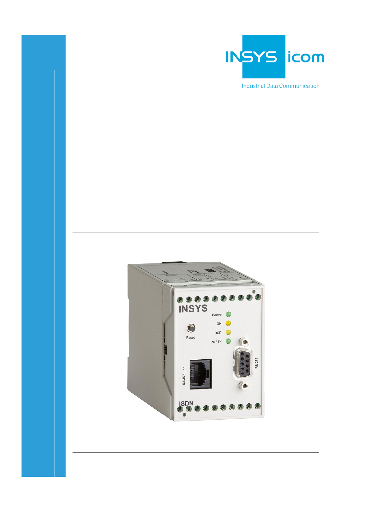
INSYS ISDN TA 4.0
Manual


Copyright © June 12 INSYS MICROELECTRONICS GmbH
Any duplication of this manual is prohibited. All rights on this documentation and
the devices are with INSYS MICROELECTRONICS GmbH Regensburg.
Trademarks
The use of a trademark not shown below is not an indication that it is freely avail-
able for use.
MNP is a registered trademark of Microcom Inc.
IBM PC, AT, XT are registered trademarks of International Business Machine Corporation.
INSYS®, e-Mobility LSG® and e-Mobility PLC® are registered trademarks of INSYS
MICROELECTRONICS GmbH.
Windows™ is a registered trademark of Microsoft Corporation.
Linux is a registered trademark of Linus Torvalds.
Publisher:
INSYS MICROELECTRONICS GmbH
Hermann-Köhl-Str. 22
D-93049 Regensburg, Germany
Phone: +49 941 58692 0
Fax: +49 941 58692 45
E-mail: info@insys-icom.com
Internet: http://www.insys-icom.com
Date: Jun-12
Item: 31-22-03.116
Version: 2.0
Language: EN

Content
1 Preface.....................................................................................................7
1.1 Defects Liability Terms ..........................................................................................7
1.2 Marking of Warnings and Notes............................................................................ 8
1.2.1 Symbols and Key Words.......................................................................... 8
1.3 Symbols and the Formatting in this Manual ..........................................................9
2 Safety.....................................................................................................10
2.1 Usage According to the Regulations ...................................................................10
2.2 Permissible Technical Limits................................................................................11
2.3 Responsibilities of the Operator........................................................................... 11
2.4 Qualification of the Personnel..............................................................................11
2.5 Instructions for Transport and Storage ................................................................11
2.6 Markings on the Product ..................................................................................... 12
2.7 Environmental Protection ....................................................................................12
2.8 Safety Instructions for Electrical Installation........................................................ 13
2.9 General Safety Instructions..................................................................................13
1 Scope of Delivery...................................................................................15
2 Technical Data .......................................................................................16
2.1 Physical Features.................................................................................................16
2.2 Technological Features........................................................................................17
2.3 Certifications........................................................................................................17
3 Display and Control Elements ................................................................ 18
3.1 Meaning of the Displays......................................................................................19
3.2 Function of the Control Elements ........................................................................ 19
4 Connections...........................................................................................20
4.1 Front Panel Connections......................................................................................20
4.2 Terminal Connections on the Top........................................................................21
4.3 Terminal Connections on the Bottom .................................................................. 22
4.4 Pin Assignment of the Serial Interface.................................................................23
4.5 Pin Assignment of the S0 Interface .....................................................................23
5 Function Overview.................................................................................24
6 Mounting ...............................................................................................26
7 Initial Operation......................................................................................30
8 Operating Principle ................................................................................32
8.1 Operation with the Terminal Program..................................................................32
8.2 Operation with HSComm ISDN ...........................................................................34
8.3 HMI of the Software HSComm ISDN ..................................................................35
4 Jun-12

Contents
9 Functions ...............................................................................................39
9.1 Establishing or Accepting a Data Connection......................................................39
9.2 Querying the Alarm Inputs...................................................................................41
9.3 Automatic Call ..................................................................................................... 42
9.3.1 Configuring an Automatic Call ............................................................... 42
9.3.2 Disabling an Automatic Call ................................................................... 45
9.4 Data Flow Control................................................................................................ 46
9.4.1 Hardware Data Flow Control (RTS/CTS)................................................. 46
9.4.2 Software Data Flow Control with XON/XOFF ........................................ 47
9.5 Remote Configuration..........................................................................................48
9.5.1 Remotely Configuring the INSYS ISDN TA 4.0 ...................................... 48
9.5.2 Configuring the Remote Configuration Number .................................... 49
9.5.3 Configuring the Remote Configuration Password ................................. 49
9.5.4 Configuring the Permitted Callers for Remote Configuration ................ 49
9.6 Connection Configuration of the INSYS ISDN TA 4.0 at the ISDN Basic Access .51
9.6.1 Configuration at Multipoint Interface (PMP, Point-to-Multipoint).......... 51
9.6.2 Configuration at Point-to-Point Interface (PTP, Point-to-Point).............. 52
9.7 Control Outputs ................................................................................................... 53
9.8 Security Callback .................................................................................................54
9.9 Selective Call Acceptance....................................................................................56
9.10 TA+Configurator..................................................................................................58
9.11 Configuring the Transfer Protocol........................................................................59
9.12 Outputting CLIP of Incoming Calls ......................................................................61
9.13 Sending Messages via Data Connection, SMS or E-Mail..................................... 62
9.13.1 Sending Messages via Data Connection................................................ 62
9.13.2 Sending Messages via SMS................................................................... 64
9.13.3 Sending Messages via E-Mail ................................................................ 66
9.14 Manual Sending of Messages..............................................................................69
9.15 Resetting the Device............................................................................................70
10 ISDN Error Messages.............................................................................71
10.1 Extended Error Messages with ISDN...................................................................73
10.2 Firmware Update.................................................................................................76
11 Firmware History ...................................................................................79
12 AT Command Reference ........................................................................ 80
13 Special ISDN Parameters .......................................................................88
14 S Register ..............................................................................................90
15 TA+Configurator Command Reference..................................................91
16 SMSC Numbers for SMS Dispatch via ISDN..........................................93
17 Waste Disposal ......................................................................................94
17.1 Repurchasing of Legacy Systems........................................................................94
18 Declaration of Conformity ...................................................................... 95
Jun-12 5

Content
19 Tables and Diagrams..............................................................................96
19.1 List of Tables .......................................................................................................96
19.2 List of Diagrams ..................................................................................................96
20 Index ......................................................................................................97
6 Jun-12

INSYS ISDN TA 4.0 Preface
1 Preface
This manual allows for the safe and efficient use of the product. The manual is part
of the product and must always be stored accessible for installation, commissioning and operating personnel.
1.1 Defects Liability Terms
A usage not according to the intended purpose, an ignorance of this documentation, the use of insufficiently qualified personnel as well as unauthorised modifications exclude the liability of the manufacturer for damages resulting from this. The
liability of the manufacturer ceases to exist.
The regulations of our Delivery and Purchasing Conditions are effective. These can
be found on our website (www.insys-icom.de/imprint/) under “General Terms and
Conditions“.
7

Preface INSYS ISDN TA 4.0
1.2 Marking of Warnings and Notes
1.2.1 Symbols and Key Words
Danger!
Risk of severe or fatal injury
One of these symbols in conjunction with the key word
Danger indicates an imminent danger. It will cause death or
severe injuries if not avoided.
Warning!
Personal injury
This symbol in conjunction with the key word Warning
indicates a possibly hazardous situation. It might cause
death or severe injuries if not avoided.
Caution!
Slight injury and / or material damage
This symbol in conjunction with the key word Caution
indicates a possibly hazardous or harmful situation. It might
cause slight or minor injuries or a damage of the product or
something in its vicinity if not avoided.
Note
Improvement of the application
This symbol in conjunction with the key word Note
indicates hints for the user or very useful information. This
information helps with installation, set-up and operation of
the product to ensure a fault-free operation.
8

INSYS ISDN TA 4.0 Preface
1.3 Symbols and the Formatting in this Manual
This section describes the definition, formatting and symbols used in this manual.
The various symbols are meant to help you read and find the information relevant
to you. The following text is structured like a typical operating instruction of this
manual.
Bold print: This will tell you what the following steps will result in
After that, there will be a detailed explanation why you could perform the
following steps to be able to reach the objective indicated first. You can
decide whether the section is relevant for you or not.
An arrow will indicate prerequisites which must be fulfilled to be able to
process the subsequent steps in a meaningful way. You will also learn
which software or which equipment you will need.
1. One individual action step: This tells you what you need to do at this
point. The steps are numbered for better orientation.
A result which you will receive after performing a step will be marked
with a check mark. At this point, you can check if the previous steps
were successful.
Additional information which you should consider are marked with a
circled "i". At this point, we will indicate possible error sources and tell
you how to avoid them.
Alternative results and steps are marked with an arrow. This will tell
you how to reach the same results performing different steps, or what
you could do if you didn't reach the expected results at this point.
9

Safety INSYS ISDN TA 4.0
2 Safety
The Safety section provides an overview about the safety instructions, which must
be observed for the operation of the product.
The product is constructed according to the currently valid state-of-the-art technology and reliable in operation. It has been checked and left the factory in flawless
condition concerning safety. In order to maintain this condition during the service
life, the instructions of the valid publications and certificates must be observed and
followed.
It is necessary to adhere to the general safety instructions must when operating the
product. The descriptions of processes and operation procedures are provided with
precise safety instructions in the respective sections in addition to the general
safety instructions.
Moreover, the local accident prevention regulations and general safety regulations
for the operating conditions of the device are effective.
An optimum protection of the personnel and the environment from hazards as well
as a safe and fault-free operation of the product is only possible if all safety instructions are observed.
2.1 Usage According to the Regulations
The product may only be used for the purposes specified in the function overview.
In addition, it may be used for the following purposes:
Usage and mounting in an industrial cabinet.
Switching and data transmission functions in machines according to
the machine directive 2006/42/EC.
Usage as data transmission device for a PLC.
The product may not be used for the following purposes and used or operated under the following conditions:
Controlling or switching of machines and systems, which do not
comply with the directive 2006/42/EC.
Usage, controlling, switching and data transmission of machines and
systems, which are operated in explosive atmospheres.
Controlling, switching and data transmission of machines, which may
involve risks to life and limb due to their functions or when a
breakdown occurs.
10

INSYS ISDN TA 4.0 Safety
2.2 Permissible Technical Limits
The product is only intended for the use within the permissible technical limits
specified in the data sheets.
The following permissible limits must be observed:
The ambient temperature limits must not be fallen below or
exceeded.
The supply voltage range must not be fallen below or exceeded.
The maximum humidity must not be exceeded and condensate
formation must be prevented.
The maximum switching voltage and the maximum switching current
load must not be exceeded.
The maximum input voltage and the maximum input current must not
be exceeded.
2.3 Responsibilities of the Operator
As a matter of principle, the operator must observe the legal regulations, which are
valid in his country, concerning operation, functional test, repair and maintenance
of electrical devices.
2.4 Qualification of the Personnel
The installation, commissioning and maintenance of the product must only be performed by trained expert personnel, which has been authorised by the plant operator. The expert personnel must have read and understood this documentation and
observe the instructions.
Electrical connection and commissioning must only be performed by a person, who
is able to work on electrical installations and identify and avoid possible hazards
independently, based on professional training, knowledge and experience as well
as knowledge of the relevant standards and regulations.
2.5 Instructions for Transport and Storage
The following instructions must be observed:
Do not expose the product to moisture and other potential hazardous
environmental conditions (radiation, gases, etc.) during transport and
storage. Pack product accordingly.
Pack product sufficiently to protect it against shocks during transport
and storage, e.g. using air-cushioned packing material.
Check product for possible damages, which might have been caused by improper
transport, before installation. Transport damages must be noted down to the shipping documents. All claims or damages must be filed immediately and before installation against the carrier or party responsible for the storage.
11

Safety INSYS ISDN TA 4.0
2.6 Markings on the Product
The identification plate of the product is either a print or a label on a face of the
product. Amongst other things, it contains the following markings, which are explained in detail here.
Observe manual
This symbol indicates that the manual of the product
contains essential safety instructions that must be followed
implicitly.
Dispose waste electronic equipment
environmentally
This symbol indicates that waste electronic equipment
must be disposed separately from residual waste via
appropriate collecting points. See also Section Disposal in
this manual.
CE marking
By applying a CE marking, the manufacturer confirms that
the product complies with the European directives that
apply product-specific.
Appliance Class II – double insulated
This symbol indicates that the product complies with
Appliance Class II
2.7 Environmental Protection
Dispose the product and the packaging according to the relevant environmental
protection regulations. The Waste Disposal section in this manual contains notes
about disposing the product. Separate the packaging components of cardboard
and paper as well as plastic and deliver them to the respective collection systems
for recycling.
12
INSYS ISDN TA 4.0 Safety
2.8 Safety Instructions for Electrical Installation
The electrical connection must only be made by authorised expert personnel according to the wiring diagrams.
The notes to the electrical connection in the manual must be observed. Otherwise,
the protection category might be affected.
The safe disconnection of circuits, which are hazardous when touched, is only ensured if the connected devices meet the requirements of VDE T.101 (Basic requirements for safe disconnection).
The supply lines are to be routed apart from circuits, which are hazardous when
touched, or isolated additionally for a safe disconnection.
2.9 General Safety Instructions
Caution!
Moisture and liquids from the environment may seep into
the interior of the product!
Fire hazard and damage of the product.
The product must not be used in wet or damp
environments, or in the direct vicinity of water. Install the
product at a dry location, protected from water spray.
Disconnect the power supply before you perform any work
on a device which may have been in contact with moisture.
Caution!
Short circuits and damage due to improper repairs and
modifications as well as opening of maintenance areas.
Fire hazard and damage of the product.
It is not permitted to open the product for repair or
modification.
Caution!
Overcurrent of the device supply!
Fire hazard and damage of the product due to overcurrent.
The product must be secured with a suitable fuse against
currents exceeding 1.6 A.
13

Safety INSYS ISDN TA 4.0
Caution!
Overvoltage and voltage peaks from the mains supply!
Fire hazard and damage of the product due to overvoltage.
Install suitable overvoltage protection.
Caution!
Damage due to chemicals!
Ketones and chlorinated hydrocarbons dissolve the plastic
housing and damage the surface of the device.
Never let the device come into contact with ketones (e.g.
acetone) or chlorinated hydrocarbons, such as
dichloromethane.
14

INSYS ISDN TA 4.0 Scope of Delivery
1 Scope of Delivery
The scope of delivery for the INSYS ISDN TA 4.0 includes all accessories listed
below. Please check if all accessories are included in the box. If a part is missing or
damaged, please contact your distributor.
1 INSYS ISDN TA 4.0
2 Cable:
1 ISDN – S0 connection cable (RJ45 to RJ45)
1 serial cable with 9-pin Sub-D connector to connect to the PC
1 Manual
15
Technical Data INSYS ISDN TA 4.0
2 Technical Data
2.1 Physical Features
Caution!
Overvoltage and voltage peaks in the mains supply!
Fire hazard and damage of the device due to overvoltage.
All specified data was measured with nominal input voltage, at full load, and an
ambient temperature of 25 °C. The limit value tolerances are subject to the usual
variations.
Physical Feature Value
Operating voltage minimum 10 V DC
Alarm input levels Level HIGH = 4-12 V
Input current of GND to internal +5 V typically 0.5 mA
Switch output, maximum switch
voltage
Switch output, maximum current load 1 A (DC) / 0.5 A (AC)
Power consumption idle 2 W
Power consumption connection 2.5 W
Install a suitable overvoltage protection.
maximum 60 V DC
Level LOW = 0-1 V
30 V (DC) / 42 V (AC)
Weight 250 g
Dimensions (Width x Depth x Height) 55 mm x 110 mm x 75 mm
Temperature range 0 °C – 55 °C
Maximum permissible humidity 95% non-condensing
Table 1: Physical Features
16
INSYS ISDN TA 4.0 Technical Data
2.2 Technological Features
Technological Feature Description
Protection class Housing IP40
Terminals IP20
Command sets Hayes dial (AT command set), V25bis
async. Hotline 108 DTR
Transmission standards B channel V.110, X75, X25/X31, HDLC
(transparent)
Transmission standards D channel DSS1, JATE, VNx, AUSTEL, X.31 D
Transmission speed in D channel: 9.600 bps (X.31-D)
Transmission speed in B channel: 64.000 bps
Table 2: Technological Features
2.3 Certifications
The INSYS ISDN TA 4.0 has the following license number for the connection to the
PSTN: CE-0682 for Europe (EC), Switzerland and Norway. The INSYS ISDN TA 4.0
is conform to the European safety requirements IEC 60 950.
The INSYS ISDN TA 4.0 has been developed in compliance with the following
guidelines and standards:
R&TTE 1999/5/EG
DIN EN 55022 Class B
DIN EN 61000-6-2
DIN EN 60950-1
CTR3
17
Display and Control Elements INSYS ISDN TA 4.0
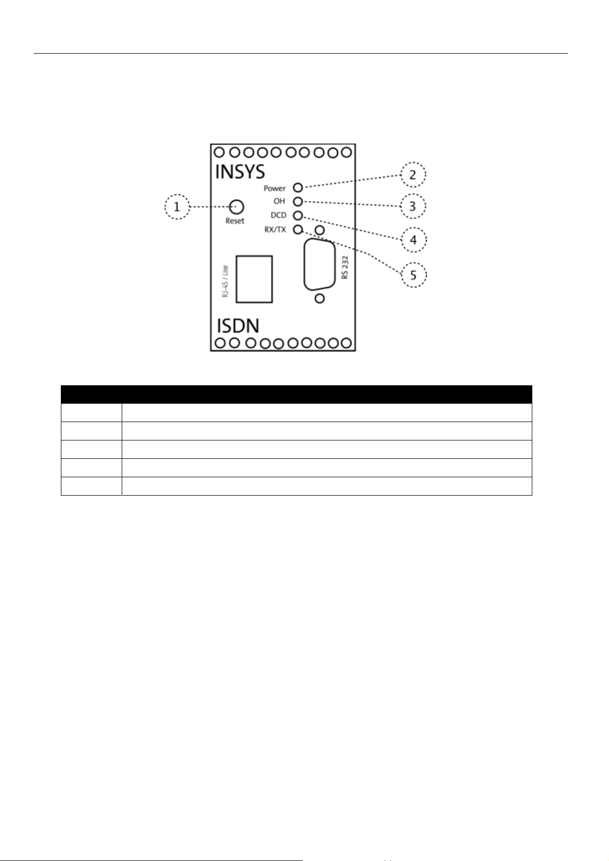
3 Display and Control Elements
Figure 1: LEDs on the front panel of the device
Position Description
1 Reset key
2 Power LED
3 Off Hook LED
4 Data Carrier Detect LED
5 Receive & Transmit LED
Table 3: Description of the display and control elements on the front panel of the device
18
INSYS ISDN TA 4.0 Display and Control Elements
3.1 Meaning of the Displays
Description Display Meaning
Power LED LED on Supply voltage available
LED off No supply voltage
Off Hook LED LED on As soon as an outgoing or
incoming connection is to
be established
LED off As soon as no outgoing or
incoming connection is to
be established
Data Carrier Detect LED LED on Connection to remote ter-
minal is established
LED off No connection to the re-
mote terminal established
at the moment
Receive & Transmit LED LED on Data is transmitted via the
serial interface
LED off No data is transmitted via
the serial interface at the
moment
Table 4: Meaning of the LED displays
3.2 Function of the Control Elements
Description Operation Meaning
Reset key Press for at least 1 second. Resets and restarts the
INSYS ISDN TA 4.0.
Table 5: Description of the functions and meaning of the control elements
19
Connections INSYS ISDN TA 4.0
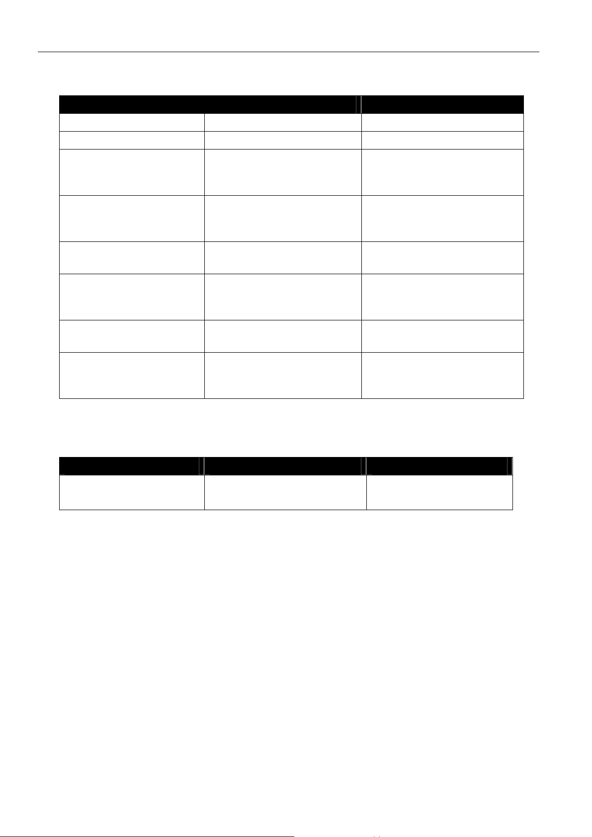
4 Connections
4.1 Front Panel Connections
Figure 2: Connections on the front panel of the device
Position Description
1 ISDN S0 connection (RJ45 line socket)
2 Serial Interface (RS232 socket)
Table 6: Description of the connections on the front panel of the device
20

INSYS ISDN TA 4.0 Connections
4.2 Terminal Connections on the Top
Figure 3: Connections on the top of the device
Terminal Description Description
1 GND Ground
2 X1 Reserved
3
4 GND Ground
5 GND Ground
6 Reset Reset input
7 GND Ground
8 Input 1 Alarm input 1
9 Input 2 Alarm input 2
10 GND Ground
Table 7: Description of the connections on the top of the device
10 ... 60 VDC Power supply 10 V - 60 V DC
21

Connections INSYS ISDN TA 4.0
4.3 Terminal Connections on the Bottom
Figure 4: Connections on the bottom of the device
Terminal Description Description
11 OUT 1-NC Output 1 normally closed
12 OUT 1 Output 1
13
14 OUT 2-NC Output 2 normally closed
15 OUT 2 Output 2
16 OUT 2-NO Output 2 normally open
17 b2 Transmitting line A (PIN 6 on RJ45 connector)
18 b1 Receive line A (PIN 5 on RJ45 connector)
19 a1 Receive line B (PIN 4 on RJ45 connector)
20 a2 Transmitting line B (PIN 3 on RJ45 connector)
Table 8: Description of the connections on the bottom of the device
OUT 1-NO Output 1 normally open
22
INSYS ISDN TA 4.0 Connections
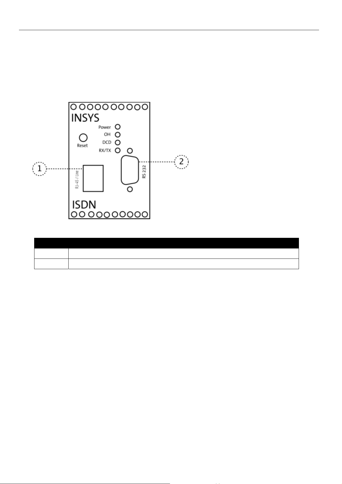
4.4 Pin Assignment of the Serial Interface
Figure 5: 9-pin Sub-D socket at the device
Pin Signal Description
1 DCD Data Carrier Detect
2 RXD Receive Data
3
4 DTR Data Terminal Ready
5 GND Ground
6 DSR Data Set Ready
7 RTS Request To Send
8 CTS Clear To Send
9 RI Ring Indication
Table 9: Description of the pin allocation of the Sub-D socket
TXD Transmit Data
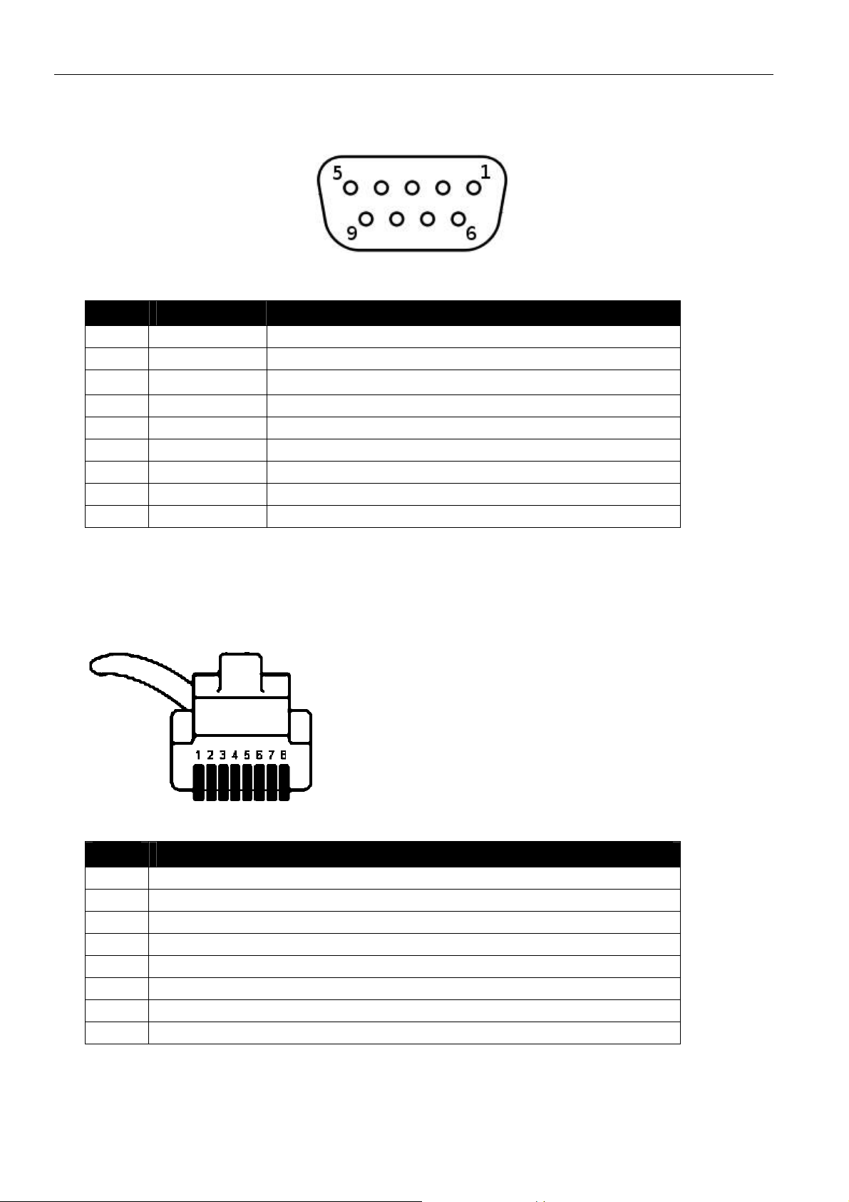
4.5 Pin Assignment of the S0 Interface
Figure 6: 8-pin Western connector (front view)
Pin Signal
1 not connected
2 not connected
3 a2
4 a1
5 b1
6 b2
7 not connected
8 not connected
Table 10: Assignment of the RJ45 connector
23

Function Overview INSYS ISDN TA 4.0
5 Function Overview
The INSYS ISDN TA 4.0 provides you with the following functions:
Operation at ISDN point-to-point and multipoint interface
The INSYS ISDN TA 4.0 can be operated at ISDN point-to-point
interfaces as well as at multipoint interfaces.
Different transfer protocols
The INSYS ISDN TA 4.0 supports different transfer protocols, like e.g.
X.75, V.110 and HDLC (for PPP connections).
Data buffer for serial data transmission
The INSYS ISDN TA 4.0 provides send and receive buffers to adjust
the INSYS ISDN TA 4.0 to the data processing speed of the
application.
Hardware and software data flow control
The INSYS ISDN TA 4.0 can interrupt the data flow of the application
via the control lines of the serial interface, if the buffers of the INSYS
ISDN TA 4.0 exceed a certain level. An application can also prompt
the INSYS ISDN TA 4.0 via a control line to interrupt the data flow. As
an alternative, the INSYS ISDN TA 4.0 can control the data flow via
XOFF/XON characters in the data stream.
Selective Call Acceptance
The INSYS ISDN TA 4.0 can be set to accept only calls from phone
numbers that were previously stored.
Security Callback
The called INSYS ISDN TA 4.0 can initiate an automatic call to a
predefined number, if a specified caller could be identified using CLIP.
Automatic call
The INSYS ISDN TA 4.0 can initiate an automatic call either
depending on the DTR signal or independent of a status line.
Control outputs, controllable locally and remote
The INSYS ISDN TA 4.0 has two potential-free control outputs, which
can be used to switch other functions in an application.
Control outputs, controllable locally and remote
The INSYS ISDN TA 4.0 has two potential-free alarm inputs, which
can be used to query states of an application.
24

INSYS ISDN TA 4.0 Function Overview
Sending messages via data connection, SMS or e-mail
The INSYS ISDN TA 4.0 has two digital alarm inputs, which can be
used to establish connections or to send messages via SMS and email via a SMS provider. The dispatch can also be triggered via the
serial interface or AT commands.
Remote configuration
The INSYS ISDN TA 4.0 can be configured remotely using another
INSYS ISDN device and a terminal program.
25
Mounting INSYS ISDN TA 4.0
6 Mounting
This section describes how to mount the INSYS ISDN TA 4.0 to a DIN rail,
connect the power supply and uninstall it again. Observe the instructions in
the "Safety" section of this manual, in particular the "Safety Instructions for
Electrical Installation" for that purpose unconditionally.
Caution!
Moisture and liquids from the environment may seep into
the interior of the INSYS ISDN TA 4.0!
Fire hazard and damage of the product.
The INSYS ISDN TA 4.0 must not be used in wet or damp
environments, or in the direct vicinity of water. Install the
INSYS ISDN TA 4.0 at a dry location, protected from water
spray. Disconnect the power supply before you perform
any work on a INSYS ISDN TA 4.0 which may have been in
contact with moisture.
Caution!
The device could be destroyed if the wrong power supply is
used!
If the INSYS ISDN TA 4.0 is operated with a power supply
that supplies a voltage exceeding the permissible operating
voltage of the INSYS ISDN TA 4.0, the device will be
destroyed.
Make sure that you use the suitable power supply. Refer to
the section Technical Data for the proper voltage range of
the INSYS ISDN TA 4.0.
26
INSYS ISDN TA 4.0 Mounting
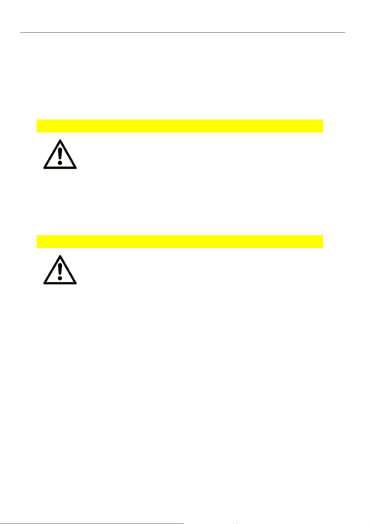
Mounting the device to the DIN rail
How to mount the INSYS ISDN TA 4.0 to a DIN rail:
1. Position the device at the DIN rail as seen in the following diagram.
There are two snap-in hooks at the upper and lower edge of the DIN
rail groove of INSYS ISDN TA 4.0. Hook the upper one into place
behind the upper edge of the DIN rail.
2. Lift the INSYS ISDN TA 4.0 perpendicular to the DIN rail until the two
lower, flexible snap-in hooks engage in the DIN rail.
The INSYS ISDN TA 4.0 is now readily mounted.
Connecting the power supply
The device has already been mounted to the DIN rail.
The power supply is connected and switched off.
1. Connect the ground lead of the power supply to the terminal "GND".
2. Connect the plus pole of the power supply to the terminal for the
power supply.
The INSYS ISDN TA 4.0 is now connected to the power supply.
27

Mounting INSYS ISDN TA 4.0
Disconnecting the power supply
The device is mounted to the DIN rail.
The power supply is connected and switched off.
1. Disconnect the ground lead of the power supply from the terminal
"GND".
2. Disconnect the plus pole of the power supply from the terminal for
the power supply.
The INSYS ISDN TA 4.0 is disconnected from the power supply.
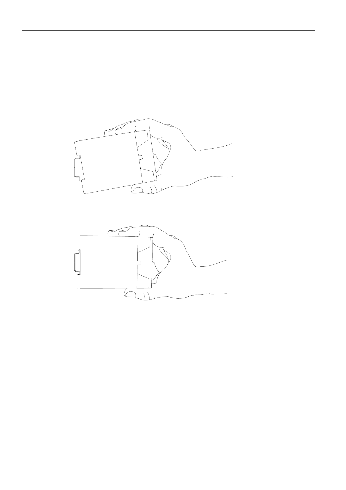
Uninstalling the device from the DIN rail
How to uninstall the INSYS ISDN TA 4.0 from a DIN rail in a switch cabinet:
You will need a Phillips screwdriver with a 4.5 mm blade.
The power supply of the switch cabinet is switched off and secured against
being switched on accidentally.
All cables at the INSYS ISDN TA 4.0 are disconnected.
1. Insert the Philips screwdriver into the groove in the bottom of the
INSYS ISDN TA 4.0 as shown in the following figure.
2. Turn the Philips screwdriver into the direction of the INSYS ISDN TA
4.0 as shown in the following figure.
28

INSYS ISDN TA 4.0 Mounting
The plastic spring of the snap-in hook is stretched.
3. While you hold the plastic spring apart with the lower snap-in hooks,
pull the INSYS ISDN TA 4.0 away from the DIN rail.
4. Un-hook the INSYS ISDN TA 4.0 and take it off perpendicularly to the
DIN rail.
The INSYS ISDN TA 4.0 is now removed.
29

Initial Operation INSYS ISDN TA 4.0
7 Initial Operation
This section describes how to commission the INSYS ISDN TA 4.0, i.e.
connect the INSYS ISDN TA 4.0 to a PC, connect it via an NTBA to the ISDN
network and test it.
Connecting the INSYS ISDN TA 4.0 to a PC
How to connect the INSYS ISDN TA 4.0 to a PC via the serial interface.
You will need the 9-pin serial cable.
You will need a free serial interface at the PC.
Primarily use serial interfaces, which exist at the PC as "real"
hardware. USB-to-Serial solutions might cause problems.
2. Connect the 9-pin serial cable with the INSYS ISDN TA 4.0 and tighten
the screws of the connector.
3. Connect the 9-pin serial cable to a free serial interface of your PC.
Connecting the INSYS ISDN TA 4.0 to the ISDN network
You will need the enclosed phone cable
You will need an NTBA, which is connected to the ISDN network or a
PABX with S0 bus.
1. Plug the RJ45 connector of the cable into the RJ45 phone socket at
the INSYS ISDN TA 4.0.
2. Plug the other RJ45 connector of the cable into the S0 socket of your
NTBA or your PABX to connect the INSYS ISDN TA 4.0 with the
public ISDN network.
Testing the INSYS ISDN TA 4.0
The INSYS ISDN TA 4.0 is connected to the PC.
The power supply of the INSYS ISDN TA 4.0 is switched on.
A terminal program, e.g. Teraterm, is installed on the PC.
1. Open your terminal program.
2. Open the serial interface, to which the INSYS ISDN TA 4.0 is
connected.
3. Enter AT into your terminal program.
30

INSYS ISDN TA 4.0 Initial Operation
You will receive the reply OK.
The RX/TX LED is illuminated as long as you are entering.
g as
If the RX/TX LED at INSYS ISDN TA 4.0 does not illuminate as lon
If you don't receive an OK, check the connection and check whether
the INSYS ISDN TA 4.0 is supplied with power. Repeat the test.
you enter AT and receive an OK, it might
a different modem (e.g. with the internal mode
In this case, check to which interface your INSY
actually connected and repeat the test.
be that you are connected to
m of the laptop or PC).
S ISDN TA 4.0 is
The INSYS ISDN TA 4.0 is ready for operation.
31

Operating Principle INSYS ISDN TA 4.0
8 Operating Principle
This chapter describes the basic procedures to operate and configure an INSYS
ISDN TA 4.0. In addition, you get an overview about the operating elements of the
HSComm software.
There are to methods to operate and configure the INSYS ISDN TA 4.0. In general,
the INSYS ISDN TA 4.0 is configured and operated via AT commands. An own
command set is used for special ISDN parameters. A TA+Configurator with special
command set is used for remote configuration. You can enter the different
command sets using a terminal program. Alternatively, you can configure the most
important functions comfortably using the configuration software HSComm.
8.1 Operation with the Terminal Program
In general, any terminal program can be used. We recommend the program
Teraterm from T.Teranishi. It is available free of cost on the Internet at
http://hp.vector.co.jp/authors/VA002416/teraterm.html.
Configuring and operating the INSYS ISDN TA 4.0 with a terminal program
How to configure and operate the INSYS ISDN TA 4.0 with a terminal
program.
The INSYS ISDN TA 4.0 is connected to the PC and switched on.
A terminal program is installed on the PC.
1. Start your terminal program.
2. Select the serial port, to which your INSYS ISDN TA 4.0 is connected.
COM1 under Windows corresponds to /dev/ttyS0 under Linux.
3. Type the character string AT into the terminal program. Complete the
entry by pressing the Enter key.
Each command input starts with AT and is completed with the Enter
key.
The
INSYS ISDN TA 4.0 replies with
OK.
4.
32
If the INSYS ISDN
probable reasons:
a) the INSYS ISDN TA 4.0 is switched off or
b) the INSYS ISDN
and repeat step 3.
Configure the INSYS ISDN TA 4.0 using AT commands.
TA 4.0 does not respond, this may have two
TA 4.0 is connected to another serial port. Check it

INSYS ISDN TA 4.0 Operating Principle
It might be necessary to change to the "TA+Configurator" for some
functions. You use the own command set for the TA+Configurator
here instead of the AT command set. Start the TA+Configurator in the
terminal program by entering the command ATCONF and leave the
TA+Configurator with the command QUIT.
A reference of the TA+Configurator commands can be found in the
chapter "TA+Configurator Command Reference".
A reference of the AT commands can be found in the chapter "AT
Command Reference".
5. Save your entries with AT&W.
Not all configurations at the INSYS ISDN TA 4.0 need to be saved by
entering AT&W. Some settings are automatically saved immediatel
However, we recommend to transmit the command AT&W to the
INSYS ISDN TA 4.0 as last step of the configuration procedure. This
ensures that all settings are saved and available after the next restart.
y.
33

Operating Principle INSYS ISDN TA 4.0
8.2 Operation with HSComm ISDN
The software HSComm allows a comfortable configuration of the INSYS ISDN
TA 4.0. HSComm provides an interface for the parameters of the most
important AT commands of the INSYS ISDN TA 4.0. The operation is mostly
self-explanatory. You can download the latest version of the software from the
INSYS MICROELECTRONICS website (www.insys-tec.de).
Configuring and operating the INSYS ISDN TA 4.0 with HSComm
How to configure the INSYS ISDN TA 4.0 with the software HSComm.
The INSYS ISDN TA 4.0 is connected to the PC and switched on.
The software HSComm is installed on the PC.
1. Start the program HSComm ISDN.
During start-up, the program automatically tries to read out the
settings of the INSYS ISDN TA 4.0 with the previously configured
interface parameters.
A message window indicating "Request system status..." is displayed.
nu, if the
Select the correct COM port in the "Serial Interface" me
message "unknown communication module" appears.
. A message window
The settings are read out after a short period
indicating "System status OK" is displayed.
2. Click OK in the status message.
3. Enter the required settings now.
4. Then click the button Send (Figure 7, Position 19).
A message window indicating "Sending/receiving data..." is displayed.
The program transfer s the settings to the INSYS ISDN TA 4.0 now and
saves them there.
A message window indicating "Writing data to device... OK!" is
displayed.
5. Click OK in the status message.
34

INSYS ISDN TA 4.0 Operating Principle
8.3 HMI of the Software HSComm ISDN
The software interface is shown in the following. These illustrations should help
you finding the different settings in the software.
Figure 7: HSComm ISDN - tab "ISDN"
35

Operating Principle INSYS ISDN TA 4.0
Position Function / Description
1 Saving and loading of setting files.
2 Setting the serial interface of the PC.
3 Button for opening the internal terminal program.
4 Button for changing from terminal view to configuration view.
5 -Function not available anymore6 Setting the DTR behaviour
7 Reading out the settings, resetting the INSYS ISDN TA 4.0.
8 Setting the HMI language.
9 Loading or saving PLC settings.
10 Program help.
11 Program version info.
12 Protocol settings panel for the B channel protocol.
13 Setting the own phone number (MSN).
14 Button for reading out the settings from the INSYS ISDN TA 4.0.
15 Configuring the type of connection.
16 Button for resetting the INSYS ISDN TA 4.0.
17 Button for sending the default settings to the INSYS ISDN TA 4.0.
18 Displaying the serial interface speed at the INSYS ISDN TA 4.0.
19 Button for transferring the settings to the INSYS ISDN TA 4.0.
20 Status line; indicating status and settings of the used serial PC inter-
face.
21 Configuration of the exchange code when using a PABX.
22 Configuration for the connection establishment to the INSYS ISDN TA
4.0.
23 Configuring the flow control.
24 Configuring the safety functions.
25 Tab for selecting the different configuration areas.
Table 11: Description of the functions at the HSComm tab "ISDN"
36

INSYS ISDN TA 4.0 Operating Principle
Figure 8: HSComm ISDN - tab "Alarm inputs"
Position Function / Description
1 Tab for selecting the different configuration areas.
2 Selecting the message type in case of an alarm.
3 Message text, which is connected to the collective message.
4 Message text, which is connected to the collective message.
5 Target number of the recipient, which is intended to get the message.
6 Collective message text, which precedes all messages.
7 Service Center Number
8 Activating the respective alarm input
Table 12:Description of the functions at the HSComm tab "Alarm inputs"
37

Operating Principle INSYS ISDN TA 4.0
Figure 9: HSComm ISDN - tab "Control outputs"
Position Function / Description
1 Tab for selecting the different configuration areas.
2 Manually switching output 2
3 Manually switching output 1
Table 13:Description of the functions at the HSComm tab "Control outputs"
38

INSYS ISDN TA 4.0 Functions
9 Functions
9.1 Establishing or Accepting a Data Connection
The INSYS ISDN TA 4.0 can call another ISDN TA (ISDN Terminal Adapter) via the
phone line and establish a data connection. After dialling a phone number, the
INSYS ISDN TA 4.0 synchronises with the called TA and opens a data connection.
All incoming characters are transmitted to the other (called) TA during the active
data connection. Therefore, AT commands are not processed during a connection.
The INSYS ISDN TA 4.0 must be changed to command mode again using an
"Escape sequence" that it processes AT commands again during an active
connection. Then, the local INSYS ISDN TA 4.0 processes the entered characters as
AT commands and does not transmit them to the remote terminal.
The INSYS ISDN TA 4.0 can accept an incoming connection in the same way. For
this, the "application" or the PC with the terminal program must support the
hardware data flow control at the serial interface, otherwise, the INSYS ISDN TA
4.0 does not accept the incoming connection. In this case, the hardware data flow
control must be disabled in the INSYS ISDN TA 4.0 that a connection is accepted
regardless of the status of the application. It answers after the configured number
of ring tones and opens a connection.
This hardware data flow control is activated by default.
Configuration with HSComm
The HSComm enables to establish a connection via the integrated
terminal program. Click "Terminal" (page 35, Figure 7, position 3) in the
menu bar of HSComm, to open the integrated terminal program.
Configuration with AT commands
In order to establish a data
connection with the INSYS ISDN
TA 4.0, use the command
Replace <number> with the phone
number of the remote terminal.
Configure the data connection
protocol using the command
ATD<number>
ATB
Refer to the AT command
reference for protocol details.
39

Functions INSYS ISDN TA 4.0
You can also configure the data
connection protocol using the
command
AT**PROT
Refer to the AT command
reference for protocol details.
If the remote terminal accepts the
connection, the INSYS ISDN TA 4.0
CONNECT
indicates
If the remote terminal is busy, the
INSYS ISDN TA 4.0 indicates
If no connection can be
established, the INSYS ISDN TA 4.0
indicates
if the INSYS ISDN TA 4.0 cannot
start a dial-up procedure, it
indicates
In order to change to command
mode during a data connection,
use the escape sequence
No data must be transmitted for 1
second before and after that the
INSYS ISDN TA 4.0 changes to
command mode.
BUSY
NO CARRIER
NO DIALTONE
+++
40
In order to change from command
mode to normal data transmission
ATO
again, use the command
In order to accept an incoming
ATA
connection, use the command
In order to configure the number of
ring tones after which the INSYS
ISDN TA 4.0 answers and accepts
the connection, use the command
ATS0=<n>
Replace <n> with the number of
ring tones.
In order to terminate a connection
and cause the INSYS ISDN TA 4.0
ATH
to hang up, use the command

INSYS ISDN TA 4.0 Functions
9.2 Querying the Alarm Inputs
The INSYS ISDN TA 4.0 provides two digital inputs, which trigger an alarm
condition when connecting to ground. The status of these alarm inputs can be
queried via AT command. The INSYS ISDN TA 4.0 can send a message in case of
an alarm. This message can be sent via data connection, as SMS or as e-mail via a
service provider. The INSYS ISDN TA 4.0 evaluates a connection of the input to
ground as alarm. If no positive edge is counted at least 4 seconds after the
negative edge, an alarm will be processed. A pause of at least 5 seconds is
necessary after resetting the input before a new alarm can be triggered.
Figure 10: Pulse evaluation
Configuration with HSComm
Querying the alarm inputs with HSComm is not possible.
Configuration with AT commands
In order to query the conditions
of the alarm inputs, use the
command
The reply has the form
The value "1" indicates an open
input and the value "0" indicates
a closed input. The example on
the right indicates: input 1
closed, input 2 open.
AT*I
<input1>, <input2>
0,1
41

Functions INSYS ISDN TA 4.0
9.3 Automatic Call
The automatic call allows to initiate a call to a phone number previously stored in
the INSYS ISDN TA 4.0. There are three possibilities for initiating a call.
The call may be initiated by the DTR line of the serial interface or incoming data at
the serial interface. Additionally, the INSYS ISDN TA 4.0 can try to call a number
immediately after switching it on.
The phone number for the automatic call is taken from the dialing table "catab". If a
connection could not be established successfully, the INSYS ISDN TA 4.0 dials the
next number from the dialling list. If none of the target phone numbers from the
dialling list could be reached, the INSYS ISDN TA 4.0 initiates an automatic redial.
You can change the maximum number of attempts as well as the duration of the
pause until the next call.
9.3.1 Configuring an Automatic Call
In order to configure an automatic call, change to the Configurator mode of the
INSYS ISDN TA 4.0 and enter the target phone number first, then select the trigger
for the connection establishment and set the reset timer. The reset timer
determines the time from the reset of the INSYS ISDN TA 4.0 until the change to
the "automatic call" mode. If an automatic call is enabled, you have the possibility
to send AT commands to the INSYS ISDN TA 4.0 during this time. The INSYS ISDN
TA 4.0 does not accept AT commands anymore after you have configured and
enabled the automatic call. The reason for this is that incoming data are
immediately transmitted to the called remote terminal. An established connection
is indicated by the INSYS ISDN TA 4.0 by the "OH" LED and "DCD" LED on the
housing front.
The automatic call is disabled in default setting . The dialling table "catab" is empty.
Configuration with HSComm
A configuration with HSComm is not possible.
42

INSYS ISDN TA 4.0 Functions
Configuration with AT commands
To start the TA+Configurator, use the
command
To configure or overwrite the target phone
number(s) of the remote terminal, use the
command
Replace <n> with values from 1 to 10 (3 for
FW < 1.027).
In order to initiate an automatic call, use
the command
The parameter <n> defines the event, that
triggers the connection establishment.
Replace <n> with the value
- "6" for a connection establishment if the
control line DTR is active;
- "7" for a connection establishment if data
are received at the serial interface;
ATCONF
catab<n>=<phoneno>
cmds=<n>
- "8" for a connection establishment
independent of a control line;
In order to disable the automatic call, use
the command
in order to determine a baud rate at the
serial interface, which is set during the
automatic call, use the command
The automatic baud rate detection is
disabled during the automatic call.
In order to view the configurable baud
rates, use the command
In order to configure the reset timer, use
the command
Set the reset timer to a value of at least
4 seconds. For this, replace "n" with a value
in tenths of a second (e.g. 4 seconds is
n=40).
cmds=0
br=<n>
br?
rsttim=<n>
Save the settings with the command
save
43

Functions INSYS ISDN TA 4.0
In order to exit the TA+Configurator and
enable the function of the automatic call,
go
use the command
Further optional settings:
Termination of the call after n seconds of
an unsuccessful call. n = 3..255
cato=<n>
(default: 15).
Dialling pause of n seconds before the next
call attempt. n = 0..255
capa=<n>
(default: 3, n=0 no call attempt).
Maximum number of attempts for each
number entry in catab. n = 1..255; (default:
catry=<n>
1)
In order to configure an idle time, after
which the connection is terminated, if no
data are transmitted, use the command
idle=<n>
Replace <n> with a value in seconds.
Select n=0 to disable this function.
In order to delete a target phone number,
catab<n>=-
use the command
Save the settings with the command
save
In order to exit the TA+Configurator and
enable the function of the automatic call,
go
use the command
44

INSYS ISDN TA 4.0 Functions
9.3.2 Disabling an Automatic Call
If the function "automatic call" is enabled, the INSYS ISDN TA 4.0 does not accept
AT commands anymore. To be able to configure the INSYS ISDN TA 4.0 again, you
must disable the function.
To change the INSYS ISDN TA 4.0 to configuration mode with enabled function
"automatic call"
The function "automatic call" is active.
Your terminal program is connected to the INSYS ISDN TA 4.0.
The serial interface speed is configured to 9600 bps.
1. Press the reset key at the INSYS ISDN TA 4.0.
2. The terminal program displays the message
"+++ press <CR>, <CR>, <ESC>,<ESC> to enter TA+Configurator
+++".
This message does not appear if it is disabled by the command
AT**RSTMSG=0.
3. Quickly double-press the "Enter" key and the "ESC" key.
You are in the TA+Configurator and can configure the INSYS ISDN TA
4.0 with the dedicated TA+Configurator commands again.
4. Enter cmds=0 to disable the function "automatic call".
5. Save the settings (if desired) with the command save.
6. Exit the remote configuration with the command go.
45

Functions INSYS ISDN TA 4.0
9.4 Data Flow Control
The data flow control ensures that the data transfer is interrupted as soon as the
buffer of the INSYS ISDN TA 4.0 exceeds a certain level. Two data flow control
options are available: Via the control lines RTS and CTS, or via the control
characters XON/XOFF which are inserted into the data stream.
9.4.1 Hardware Data Flow Control (RTS/CTS)
The hardware data flow control works in two directions. When the critical buffer
level is exceeded, the INSYS ISDN TA 4.0 will set the CTS line to "low" and will
thus indicate to the application to interrupt the data flow. When the buffer is
emptied sufficiently for the INSYS ISDN TA 4.0 to be able to receive data again, the
CTS line is set to "high". Reversely, the application can also indicate to the INSYS
ISDN TA 4.0 to interrupt the data flow. This is done via the RTS line. If it is set to
"low", the INSYS ISDN TA 4.0 will interrupt the data flow to the application. The
application will set it to "high" to request data from the INSYS ISDN TA 4.0.
Data flow control is set to hardware as default setting.
Configuration with HSComm
The hardware controlled data flow control is configured on the "ISDN"
tab in the "Handshake" panel (Figure 7, page 35, position 23).
Configuration with AT commands
Enable hardware data flow control
(RTS/CTS) with the command
Disable the data flow control with the
command
AT&K=3
AT&K=0
46

INSYS ISDN TA 4.0 Functions
9.4.2 Software Data Flow Control with XON/XOFF
When the input buffer of the INSYS ISDN TA 4.0 exceeds a certain fill state, the
INSYS ISDN TA 4.0 will insert an XOFF character into the data stream to the
application. This character will cause the application to send no more data. It
depends on the according application software if the XON/XOFF data flow control
is supported.
After the input buffer of the INSYS ISDN TA 4.0 is emptied sufficiently that data
can be received again, the INSYS ISDN TA 4.0 will send an XON character to the
application. This character will cause the application to send data to the INSYS
ISDN TA 4.0 again. Analogously, the application can insert XON/XOFF characters
into the data stream to switch the data flow on and off. The XON/XOFF data flow
control is only available when the transmitted data do not contain the characters
XON or XOFF, which usually appear only in actual ASCII texts (7 bit). When binary
data (programs, etc.) are transmitted, or in the XMODEM transmission protocol, for
example, occasionally appearing XON or XOFF characters would disturb the
operation.
Configuration with HSComm
The software controlled data flow control is configured on the "ISDN" tab
in the "Handshake" panel (Figure 7, page 35, position 23).
Configuration with AT commands
Enable the software data flow control
XON/XOFF with the command
Disable the data flow control with the
command
AT&K=4
AT&K=0
47

Functions INSYS ISDN TA 4.0
9.5 Remote Configuration
You can configure the INSYS ISDN TA 4.0 with another ISDN TA from remote. You
can configure a password, authorised callers as well as a remote configuration
number to restrict access. The configuration is performed via the TA+Configurator.
This is automatically started after the connection establishment for remote
configuration.
The remote configuration is active as default. No password is entered and all callers
are authorised.
9.5.1 Remotely Configuring the INSYS ISDN TA 4.0
The following describes the commands for the remote configuration of an
INSYS ISDN TA 4.0 using a second INSYS ISDN TA 4.0:
Your terminal program is connected to the local INSYS ISDN TA 4.0.
1. Configure the B channel protocol X.75 at the local INSYS ISDN TA 4.0
using the command ATB10.
2. Establish an ISDN connection to the "Remote TA" using the AT
dialling command. Use the command ATD<phonenumber>e.
The extension "e" at the end of the phone number establishes an
internal control connection to the remote TA
The "Remote TA" replies with a password request.
password:
3. Enter the correct password.
If the INSYS ISDN TA 4.0 is configured to default settings: no
password, simply hit the Enter key.
Each line starts with a "#" character during remote configuration.
the TA+Config
commands).
In order t
showall.
urator commands (refer to table TA+Configurator
o read out the settings for example, use the command
Use
ure
4. Config
now.
5. Save the settings (if desired) with the command
6. Exit the remote configuration with the command
48
the INSYS ISDN TA 4.0, which is to be remotely configured,
save.
go.

INSYS ISDN TA 4.0 Functions
9.5.2 Configuring the Remote Configuration Number
You can assign an own, dedicated phone number for the INSYS ISDN TA 4.0 for
remote configuration access.
The phone number of the caller is not requested in default setting .
Configuration with HSComm
A remote configuration with HSComm is not possible.
Configuration with AT commands
In order to determine a separate remote
AT**rmsn=<phonenumber>
configuration number, use the command
9.5.3 Configuring the Remote Configuration Password
You can enter a password at the INSYS ISDN TA 4.0 to increase the safety of the
remote configuration.
No password is entered in default setting.
Configuration with HSComm
A remote configuration with HSComm is not possible.
Configuration with AT commands
In order to define a password, use the
command
AT**rpwd=<password>
9.5.4 Configuring the Permitted Callers for Remote Configuration
You can create a list with up to 10 (3 for FW < 1.027) phone numbers, which are
permitted as caller numbers for remote configuration of the INSYS ISDN TA 4.0.
The INSYS ISDN TA 4.0 ignores each incoming call with a phone number, which
does not match with one of the entries of the list. The INSYS ISDN TA 4.0
compares the number of the caller with each entry of the list for this. The
comparison starts with the last digit of the phone number. It will be compared until
an entry matches a caller number. If a table entry contains only an asterisk "*",
each incoming call is accepted. If the table is empty, the INSYS ISDN TA 4.0
accepts each caller for remote configuration.
49

Functions INSYS ISDN TA 4.0
The list is empty as default setting.
Configuration with HSComm
The remote configuration with HSComm is not possible.
Configuration with AT commands
In order to output the phone number of a
caller together with the RING message in
ATV2
the terminal window, use the command
In order to define the permitted caller for
remote configuration, enter the phone
number of the permitted callers in the table
racctab.
<n> is the number of the table entry and
can take on the values 1 to 10 (3 for FW <
1.027).
AT**racctab<n>=<callno
>
<callno> is the transmitted phone number
of the permitted caller.
The maximum length of the phone number
is 20 digits.
* : is a wildcard for one or more digits.
only the entered number is accepted
all numbers starting with "089123" are
AT**racctab1=089123456
AT**racctab1=*89123*
accepted
all numbers ending with "1234" are
AT**racctab1=1234
accepted
all incoming calls are accepted, without
AT**racctab1=*
sub-address
In order to query the table, use the
AT**racctab
command
In order to delete an entry, use the
AT**racctab<n>=-
command
50

INSYS ISDN TA 4.0 Functions
9.6 Connection Configuration of the INSYS ISDN TA 4.0 at
the ISDN Basic Access
9.6.1 Configuration at Multipoint Interface (PMP, Point-to-Multipoint)
In order to operate the INSYS ISDN TA 4.0 at a multipoint interface, you must
configure it accordingly and configure an own phone number (MSN). The MSN is
always configured without area code. When operating at a PABX, you must only
enter the extension number.
The operation at a multipoint interface is configured and "*" is entered as phone
number in the default setting.
Configuration with HSComm
Enable the radio button "Point to multipoint" in the "Type of connection"
panel (page 35, Figure 7, position 15) on the "ISDN" tab.
If the INSYS ISDN TA 4.0 is connected to a PABX, enter the exchange
code into the field "Characters for dial prefix" (page 35, Figure 7, position
21) in the "Connection" panel at the "ISDN" tab.
Configuration with AT commands
To configure the multipoint interface
connection type use the command
To set the phone number (MSN) use the
command
To save the settings use the command
AT**PTP=0
AT**MSN=<N>
AT&W
51

Functions INSYS ISDN TA 4.0
9.6.2 Configuration at Point-to-Point Interface (PTP, Point-to-Point)
You can operate the INSYS ISDN TA 4.0 at a point-to-point interface. A point-topoint interface is a special ISDN access, which allows that devices behind the
access are accessible from outside with dedicated extension numbers.
In order to operate the INSYS ISDN TA 4.0 at a point-to-point interface, you must
configure the "Point to point" type of connection.
This is not valid for the operation at an ISDN PABX. For this, proceed
as described under Configuration at Multipoint Interface (PMP, Pointto-Multipoint).
Configuration with HSComm
Enable the radio button "Point to point" in the "Type of connection" panel
(page 35, Figure 7, position 15) on the "ISDN" tab.
Configuration with AT commands
To configure the point-to-point interface
connection type use the command
To set the phone number (MSN) use the
command
To configure the TEI (is assigned by the
phone provider) use the command
To save the settings use the command
AT**PTP=1
AT**MSN=<N>
AT**TEI=<N>
AT&W
52

INSYS ISDN TA 4.0 Functions
9.7 Control Outputs
The INSYS ISDN TA 4.0 provides two control outputs OUT1 and OUT2 at the
bottom of the housing. The outputs are designed as potential-free change-over
relays. They can be controlled independently of each other via AT commands. The
outputs can also be switched via remote configuration. The control outputs remain
in a state until this is changed by a switch command.
The state of the control outputs can be queried in the status registers (S registers)
S14 (output 1) and S15 (output 2).
Both control outputs are not connected to GND in default setting.
Configuration with HSComm
The outputs can be opened or closed on the "Control outputs" tab in the
"Control output" panel (Figure 9, page 38, position 2 & 3).
Configuration with AT commands
To switch the outputs use the command
The following applies: <Out> is "0" for
AT*Y<out>,<state>
output 1 and "1" for output 2 and <state>
is "0" for off and "1" for on.
In order to enable output 1, use the
AT*Y0,1
command
In order to disable output 2, use the
AT*Y1,0
command
53

Functions INSYS ISDN TA 4.0
9.8 Security Callback
The Security Callback function enables the called INSYS ISDN TA 4.0 to perform an
automatic call back to a configured number. If an ISDN device tries to establish a
data connection to a remote INSYS ISDN TA 4.0, the called INSYS ISDN TA 4.0
compares the phone number of the calling party with the entries of its "Access
table". If the phone number matches with an entry, the number, which is in the
entry of the callback number, will be called back after the callback time has
expired. Otherwise, the call will be rejected. The INSYS ISDN TA 4.0 performs only
one callback attempt.
Security Callback is disabled in default setting.
Configuration with HSComm
In order to enable Security Callback, activate the checkbox "Callback"
(Figure 7, page 35, position 24) in the "Safety functions" panel on the
"ISDN" tab. Enter the phone number, which is to be dialled by the INSYS
ISDN TA 4.0 in the adjacent field.
Enter the Callback time for security callback (pause between identifying
the caller until callback) in seconds into the respective field in the "Safety
functions" panel on the "ISDN" tab (Figure 7, page 35, position 24).
In order to disable Security Callback, deactivate the checkbox "Callback"
(Figure 7, page 35, position 24) in the "Safety functions" panel on the
"ISDN" tab.
Configuration with AT commands
In order to enable Security Callback, use
AT**CMDS2=40
the command
Enter the phone number, which is to be
dialled by the INSYS ISDN TA 4.0 when
calling back, using the command
AT**CASNR=<number>
(Enter the prefix for accessing an outside
line when operating at a PABX.)
54

INSYS ISDN TA 4.0 Functions
In order to enter the phone numbers for
authentication into the access table, use
the command
<n> = memory location in the table (from 1
to 10 (5 for FW < 1.027))
<number> = phone number of the calling
party
AT**ACCTAB<n>=<number>
AT**ACCTAB1=0941249413
For example for location 1 with number
0941249413
In order to read out the table, use the
AT**ACCTAB
command
In order to delete a phone number from the
table, use the command
AT**ACCTAB<n>=-
<n> = memory location in the table (from 1
to 10 (5 for FW < 1.027))
In order to configure the callback time
(pause between call and callback), use the
command
AT**CAPA=<n>
<n> is the time in seconds
In order to save the settings, use the
AT&W
command
In order to disable Security Callback, use
AT**CMDS2=0
the command
55

Functions INSYS ISDN TA 4.0
9.9 Selective Call Acceptance
The INSYS ISDN TA 4.0 can be set to accept only calls from phone numbers that
were previously stored. The following commands allow to create a table with up to
10 (5 for FW < 1.027) numbers.
The INSYS ISDN TA 4.0 ignores each incoming call, which does not comply with
one of the table entries. The INSYS ISDN TA 4.0 compares the number of the caller
with each entry of the list. The comparison starts with the last digit of the number
until an entry complies with. If an entry of the table is configured to asterisk (*), the
INSYS ISDN TA 4.0 accepts every incoming call.
The list is empty as default setting.
Configuration with HSComm
In order to enable the selective call acceptance, activate the checkbox
"Access protection" (Figure 7, page 35, position 21) in the "Safety
functions" panel on the "ISDN" tab.
Enter the phone number of the permitted caller (Figure 7, page 35,
position 21) in the adjacent field. If you want to enter further phone
numbers, this is only possible via the AT command set.
In order to disable the selective call acceptance, deactivate the checkbox
"Access protection" (Figure 7, page 35, position 21) in the "Safety
functions" panel on the "ISDN" tab.
Configuration with AT commands
In order to use the selective call acceptance
and define the phone numbers of the
permitted callers in the table acctab, use
the command
Replace <n> with the number of the table
entry here (1 - 10 (5 for FW < 1.027)).
<callno> is the transmitted phone number
AT**acctab<n>=<callno>
of the permitted caller. The maximum
length of the phone number is 20 digits.
Use the asterisk "*" within the phone number as wildcard. This is used to replace one
or more digits in the phone number to
permit several similar pone numbers.
Example: only the entered number is
AT**acctab1=0891234567
accepted
Example: The INSYS ISDN TA 4.0 accepts
AT**acctab1=089123*
all numbers starting with 089123
56

INSYS ISDN TA 4.0 Functions
Example: The INSYS ISDN TA 4.0 accepts
AT**acctab1=*1234
all numbers ending with 1234
Example: The INSYS ISDN TA 4.0 accepts
AT**acctab1=*
all incoming calls
To query the table use the command
To delete an entry use the command
AT**acctab
AT**acctab<n>=-
In order to output the phone number of a
caller with the RING message, use the
ATV2
command
57

Functions INSYS ISDN TA 4.0
9.10 TA+Configurator
The INSYS ISDN TA 4.0 has a further command set, the so-called
"TA+Configurator", besides the AT command set. This special command set is
used in a terminal program after changing to the "TA+Configurator" besides the AT
commands. The commands of the TA+Configurator can also be entered directly by
adding the prefix AT** without having to change to the special TA+Configurator
command set. The TA+Configurator is especially used for some functions of the
INSYS ISDN TA 4.0, for example during remote configuration. A list of the
command can be found in the section "TA+Configurator Commands". The entry is
not case-sensitive.
The TA+Configurator is not active by default when operating via a terminal
program.
Configuration with HSComm
The "TA+Configurator" cannot be used via HSComm.
Configuration with AT commands
In order to use the TA+Configurator, use
the command
In order to display available parameters of a
TA+Configurator commands, use the syntax
Replace <command> with a
TA+Configurator command.
Example for a TA+Configurator command
to change the ISDN protocol to X.75
Example for a prefixed TA+Configurator
command to configure the ISDN protocol
to X.75 via a TA+Configurator command
Example for a "usual" AT command to configure the ISDN protocol to X.75
In order to exit the TA+Configurator, use
the TA+Configurator command
In order to exit the TA+Configurator, use
alternatively the TA+Configurator com-
mand
ATCONF
<command>?
Prot=10
AT**prot=10
ATB10
go
quit
58

INSYS ISDN TA 4.0 Functions
9.11 Configuring the Transfer Protocol
The information transfer in the ISDN B channel is performed via dedicated
protocols. The INSYS ISDN TA 4.0 supports different ISDN protocols, which can be
used for specific applications. The following table lists all protocols supported by
the INSYS ISDN TA 4.0 with application examples.
The X.75 protocol is enabled in default setting.
ATB Protocol Usage
0 V.110 asynchronous For connections to the GSM network (CSD data
connection).
The bit rate (300 to 38.400 bps) must be identical at
both communication partners.
3 HDLC async to sync
conversion (PPP
For remote data transmission connections or connections to an internet provider.
asynchronous)
4 HDLC transparent
(octets are packed
into HDLC frames)
Control protocol for point-to-point data transmission. Usually connection with X.75 for data protection used. HDLC uses no control characters. The
usage of "frames" and "windows" during transmission allows to detect errors and repeat the partial
transmission, if required.
5 Byte transparent
Byte-by-byte transmission without protocol.
voice connection
(raw B channel data)
6 Byte transparent data
Protocol for byte-transparent data transmission.
connection (raw B
channel data)
10 X.75 SLP Standard protocol for data transmission in packet-
switched networks in ISDN with transfer rate up to
64 kbit/s. Takes over the same tasks like V.42 for
modem connections in principle. The size of the
data blocks on level 2 (Datalength, Framesize,
Blocksize) and the maximum number of blocks to
be sent (Windowsize) can be configured.
13 V.120 asynchronous This protocol is adjusted to V.110.
20 X.31 B channel (X.25
B channel)
Protocol for data transfer in packet.switched net-
works like Datex-P of Deutsche Telekom.
21 X.31 D channel X.31 is an international manufacturer-independent
ITU standard for connecting ISDN systems to X.25
networks. Packet-mode terminals are supported by
ISDN by X.31.
31 MLPPP For channel bundling; provides a higher transmis-
sion rate of up to 128 kb/s.
Table 14: Supported ISDN protocols with usage
59

Functions INSYS ISDN TA 4.0
Configuration with HSComm
Select the desired protocol in the "Protocol" panel (Figure 7, page 35,
position 12) on the "ISDN" tab. Not all supported protocols can be
configured with HSComm.
Configuration with AT commands
To set a protocol use the command To
select the protocol, enter a value from the
ATB<n>
"AT-<n>" column of Table 14 for the
parameter <n>.
To set the V.110 asynchronous protocol
ATB0
use the command
To set the HDLC transparent protocol use
ATB4
the command
60

INSYS ISDN TA 4.0 Functions
9.12 Outputting CLIP of Incoming Calls
The INSYS ISDN TA 4.0 can output the phone number of incoming calls via its
serial interface using CLIP (Calling Line Identification Presentation). This function
can be used for example to acknowledge messages, which are sent to a mobile
phone by an application via the INSYS ISDN TA 4.0. The CLIP of the caller is output
in the format [xxxxxxxx].
Configuration with HSComm
This function can only be configured via AT commands.
Configuration with AT commands
In order to display the phone number vie
CLIP using the extended responses, use the
command
ATW1
In order to define, which type of incoming
AT#C2
calls are to be indicated use the command
In order to indicate all calls, use the com-
AT#C2=00000001
mand
In order to output the number of the last
AT#O
caller, use the command
In order to indicate only analogue calls for
AT#C2=00030012
example, use the command
61

Functions INSYS ISDN TA 4.0
9.13 Sending Messages via Data Connection, SMS or E-
Mail
The INSYS ISDN TA 4.0 monitors its alarm inputs to send a message in case of an
event. It makes three attempts to send a message regardless of the type of
transmission. If all attempts fail, no further attempt will be made. Trigger an alarm
signal again in this case.
The sent messages are composed by the group message and the according alarm
text 1 or alarm text 2. It is thus possible to specify the system with the collective
message and customize the alarm text assigned to the respective input.
No alarm is active in default setting.
9.13.1 Sending Messages via Data Connection
The INSYS ISDN TA 4.0 can establish a data connection to a remote terminal, e.g.
an INSYS ISDN TA or another ISDN modem to send messages. The INSYS ISDN TA
4.0 transmits the configured alarm text via the data connection to the other device
in this case.
Configuration with HSComm
In order to enable the alarm, check on the "Alarm inputs" tab the
checkmark (Figure 8, page 37, position 8) for the desired alarm input.
Select in the list field "Type of connection" (Figure 8, page 37, position 2)
"Data connection, hold the line" or "hang up connection".
It is not necessary to enter a Service center number when sending
messages via data connection.
Enter the Recipient phone number into the entry field "Recipient
number" (Figure 8, page 37, position 5).
In order to specify a general text (a "collective message"), which
precedes all messages, enter yo
message" (Figure 8, page 37, position 6).
In order to specify the individual message for the input, enter the
message text into the text field "Individual message" (Figure 8, page 37,
position 4 for alarm input 1 and position 3 for alarm input 2).
Enter your own phone number (MSN) on the "Mode
(Figure 7, page 35, position 13). The entry is without prefix. When
operating at a PABX, you must only enter the extension number.
ur text into the text field "Collective
m functions" tab
In order to disable the alarm, uncheck on the "Alarm inputs" tab the
checkmark (Figure 8, page 37, position 8) for the desired alarm input.
62

INSYS ISDN TA 4.0 Functions
Configuration with AT commands
In order to use the alarm, define the
recipient number, to which the message is
to be sent, first.
AT&Z1=phonenumber
When operating at a PABX, you must also
enter the outside line access code here.
Configure the message transmission for
data connection.
If you want that the connection remains
established after message dispatch, select
If you want that the connection is
terminated after message dispatch, select
in order to specify the collective message,
which precedes all messages, use:
After this command is entered, the modem
will respond and wait for the collective
message text.
The text can be a maximum of 120
characters long.
In order to enter the message text, use
for alarm input 1:
for alarm input 2:
AT*M0
AT**idle=0
AT**idle=5
AT*V
New alarm text:
AT*V1
AT*V2
After this command is entered, the modem
will respond and wait for the individual
alarm text.
New alarm text:
The text can be a maximum of 40
characters long.
How to enter the own phone number
AT**MSN=<n>
(MSN):
In order to save the settings, use the
AT&W
command
63

Functions INSYS ISDN TA 4.0
9.13.2 Sending Messages via SMS
The INSYS ISDN TA 4.0 can send an SMS to a mobile phone in case of an alarm.
The settings can differ for the different mobile phone providers. Please read up on
the currently valid settings.
The connection type depends on the type of transmission, the provider and the end
terminal. Please note that you can only specify one connection type, which is valid
for all messages of the INSYS ISDN TA 4.0. If you specify "SMS to D2-net", for
example, you can only send SMS to mobile phones in the Vodafone network. If you
enter a service center number manually, it may happen that SMS can only be sent
to certain mobile phone networks with this.
Configuration with HSComm
In order to enable the alarm, check on the "Alarm inputs" tab the
checkmark (Figure 8, page 37, position 8) for the desired alarm input.
Select the mobile phone network in the list field Type of connection
(Figure 8, page 37, position 2).
Alternatively, disable briefly "Alarm input 1/2 active" and enter then the
service center number into the field "Service center number“ (page 37,
Figure 8, position 7). The service center number 090032669005 sends
SMS to all German mobile phone networks (check call blocking of the
phone connection for 0900 numbers if required).
In order to specify a general text (a "collective message"), which
precedes all messages, enter your text into the text field "Collective
message" (Figure 8, page 37, position 6).
In order to specify the individual message for the input, enter the
message text into the text field "Individual message" (Figure 8, page 37,
position 4 for alarm input 1 and position 3 for alarm input 2).
Enter the recipient number with area code (or also with country code)
into the entry field "Recipient number" (Figure 8, page 37, position 5) for
the respec
tive alarm input.
Enter your own phone number (MSN) on the "Modem functions" tab
(Figure 7, page 35, position 13). The entry is without prefix. When
operating at a PABX, you must only enter the extensi
on number.
In order to disable the alarm, uncheck on the "Alarm inputs" tab the
checkmark (Figure 8, page 37, position 8) for the desired alarm input.
Configuration with AT commands
64

INSYS ISDN TA 4.0 Functions
In order to use the alarm, define the SMS
service center number, which is used to
send the message, first.
Request the service center number from
the respective mobile phone provider.
(When operating at a PABX, you must also
enter the outside line access code here.)
Specify your target mobile phone network
(refer to Table 15: Message transmission
type).
Example: If you want to send all messages
to mobile phones in the Vodaone network,
use
in order to specify the collective message,
which precedes all messages, use:
After this command is entered, the modem
will respond and wait for the collective
message text.
The text can be a maximum of 120
characters long.
AT&Z1=phonenumber
AT*M<n>
AT*M4
AT*V
New alarm text:
In order to enter the message text, use
for alarm input 1:
for alarm input 2:
After this command is entered, the modem
will respond and wait for the individual
alarm text.
The text can be a maximum of 40
characters long.
In order to enter the recipient number, use
the command
for alarm input 1:
for alarm input 2:
Depending on the provider, it might be
necessary to use international format here
(e.g. +49xxxxxxxxxx)
AT*V1
AT*V2
New alarm text:
AT&Z3=phonenumber
AT&Z2=phonenumber
65

Functions INSYS ISDN TA 4.0
How to enter the own phone number
(MSN):
In order to save the settings, use the
command
Transmission Protocol Data format Example
SMS to Mobile PET 8N1 T-Mobile or E-
SMS to Mobile UCP 7E1 AT*M2
SMS to Mobile PET 7E1 AT*M3
SMS to Mobile UCP 8N1 Vodafone
Table 15: Message transmission type
9.13.3 Sending Messages via E-Mail
AT**MSN=<n>
AT&W
AT*M1
Plus network
AT*M4
network
Some providers support the forwarding of SMS messages from the landline
network to an e-mail address. These SMS must have a certain format. Please
contact your provider for further information.
The following is a general configuration example of the provider Anny Way (state
12/2007):
Configuration with HSComm
In order to enable the alarm, check on the "Alarm inputs" tab the
checkmark (Figure 8, page 37, position 8) for the desired alarm input.
Select in the list field "T
"SMS to D
2-net".
ype of connection" (Figure 8, page 37, position 2)
Disable briefly "Alarm input 1/2 active" and enter the phone number
0900 32669005 into the field "Service center number“ (page 37, Figure
8, position 7). (check call blocking of the phone connection for 0900
numbers if required).
Enter the e-mail address for "Collective message" (Figure 8, page 37,
position 6), enter a blank and then start your text.
In order to specify the individual message for the input, enter the
message text into the text field "Individual message" (Figure 8, page 37,
position 4 for alarm input 1 and position 3 for alarm input 2).
Enter the phone number 6245 into the entry field Recipient number
(Figure 8, page 37, position 5) in the field of the respective alarm input.
(The note about the format of the recipient number can be ignored).
Enter your own phone number (MSN) on the "Modem functions" tab
66

INSYS ISDN TA 4.0 Functions
(Figure 7, page 35, position 13). The entry is without prefix. When
operating at a PABX, you must only enter the extension number.
In order to disable the alarm, uncheck on the "Alarm inputs" tab the
checkmark (Figure 8, page 37, position 8) for the desired alarm input.
Configuration with AT commands
In order to use the alarm, define the service
center number first. When operating at a
AT&Z1=090032669005
PABX, you must also enter the outside line
access code here.
Select the message protocol.
in order to send a valid text, the collective
message must start with the e-mail
address, followed by a blank and then the
actual alarm text.
After this command is entered, the INSYS
ISDN TA 4.0 will respond and wait for the
collective message text.
The text can be a maximum of 120
characters long.
Example
In order to enter the second part of the
message text, use
for alarm input 1:
for alarm input 2:
AT*M2
AT*V
New alarm text:
info@company.com fault
AT*V1
AT*V2
After this command is entered, the modem
will respond and wait for the individual
alarm text.
New alarm text:
The text can be a maximum of 40
characters long.
In order to enter the recipient number, use
for alarm input 1:
AT&Z3=6245
for alarm input 2:
The note about the format of the recipient
AT&Z2=6245
number can be ignored.
67

Functions INSYS ISDN TA 4.0
How to enter the own phone number
(MSN):
The dial-up attempts (1-12) for alarm
dispatch are configured with:
(default: 3 attempts)
In order to save the settings, use the
command
AT**MSN=<n>
AT**ALTRY=<n>
AT&W
68

INSYS ISDN TA 4.0 Functions
9.14 Manual Sending of Messages
The messages can also be sent manually. Precondition is that you have already
saved the required settings.
Configuration with HSComm
A manually triggered dispatch of the messages with the HSComm
software is not possible.
Configuration with AT commands
In order to send the messages manually,
use
AT*X1
for alarm input 1:
for alarm input 2:
AT*X2
69

Functions INSYS ISDN TA 4.0
9.15 Resetting the Device
The INSYS ISDN TA 4.0 can be reset (restarted) in several ways: By briefly
disconnecting the power supply, by pressing the Reset key at the front for at least
three seconds, by connecting the "RESET" terminal to the GND terminal for at least
three seconds, using an AT command, and using the Software HSComm. Resetting
the device to factory default settings is performed using an AT command.
Configuration with HSComm
In order to restart the INSYS ISDN TA 4.0, click the button "Reset
Modem" (Figure 7, page 35, position 16).
In order to reset the INSYS ISDN TA 4.0 to default settings, click the
button "Send default settings" (Figure 7, page 35, position 17).
Configuration with AT commands
In order to restart the INSYS ISDN TA 4.0,
AT**RESET
use the command
In order to reset the standard parameters of
the INSYS ISDN TA 4.0 to default settings,
AT&F
use the command
In order to reset the standard parameters
and additionally the ISDN parameters of the
AT&F1
INSYS ISDN TA 4.0 to default settings, use
the command
In order to save the default settings, use
AT&W
the command
70

INSYS ISDN TA 4.0 ISDN Error Messages
10 ISDN Error Messages
The exact failure cause is recorded in the protocol memory of the INSYS ISDN TA
4.0 in case of a faulty connection establishment. Possible error messages are
described here; a complete list of the possible error messages can be found in the
subsequent table (refer to section 10.1).
Protocol error layer 1 (error code 3301)
There is no physical connection to the ISDN network. Check the cable confection
between the ISDN adapter and the ISDN port. Are you using a suitable cable? Is
the connection socket properly installed? Is the ISDN network terminator correctly
activated? Do you have other devices on your ISDN line that are maybe faulty or
that are blocking the S0 bus?
Protocol error layer 2, e.g. DTE address not valid, TEI not valid (error code 3302)
Could not connect to the ISDN network. This may be due to a wrong ISDN
protocol. Have you set "1TR6" (German ISDN) as ISDN protocol even though your
ISDN line is set up for "DSS1" (Euro ISDN). or vice versa?
Unallocated (unassigned) number (error code 3481)
"No connection under this number". The number you are calling could not be
reached because it has no line assigned to it. The phone number has the right
format. Enquire at your telephone company or the operator of your telephone
exchange what the correct number is.
Normal call clearing (error code 3490)
"Connection terminated normally". One of the users of the connection cancelled
the connection. The connection was not cancelled by the ISDN network.
User busy (error code 3491)
"Busy". The number you are calling cannot answer any calls at the moment
because all channels are being used.
No user responding (error code 3492)
The number you are calling did not answer within the time period required by your
connection. There is probably no terminal device connected to the number you are
calling. Contact the other party to establish the cause.
No answer from user (user alerted) (error code 3493)
The number you are calling confirmed call received within the time period required,
but a connection was not established, however. If the terminal device of the other
party is a telephone, then it rang, but the call was not answered. Try again later.
71

ISDN Error Messages INSYS ISDN TA 4.0
Call rejected (error code 3495)
The device reached under the phone number refused the call, although it was not
busy and was able to answer the call. Example: if the ISDN option "Call waiting" is
activated on the other's party line, a telephone can answer your call even if a call is
in progress at the time. This error message occurs when your waiting call is
refused by the person you are trying to reach.
Number changed (error code 3496)
The phone number of the party you are calling has changed. Contact your
telephone company for the new number.
Destination out of order (error code 349B)
The terminal device on the number you are calling could not be reached, because
the port for this device did not work. Possible causes: the other party's terminal
device is not connected or not turned on, or it is not working properly. Contact the
other party to find out the cause.
Invalid number format (error code 349C)
The party you are calling could not be reached because the number you called is in
the wrong format or incomplete.
No circuit/channel available (error code 34A2)
No B channel is available for a call at the moment. Upon this, the INSYS ISDN TA
4.0 initiates a blockade release and clears a B channel with this.
ISDN network out of order (errror code 34A6)
Problems in the ISDN network. Wait a while and try again.
Temporary failure (error code 34A9)
Temporary problems in the ISDN network. You can try again immediately.
Incompatible destination (error code 34D8)
The terminal device of the other party is not compatible with the terminal device
that is making the call. The call cannot be answered, therefore. This error could
occur, for example, if the terminal device of the other party is a normal telephone.
72

INSYS ISDN TA 4.0 ISDN Error Messages
10.1 Extended Error Messages with ISDN
Cause (hex) Meaning AT re-
sponse
0000 No error
0001 NCPI ignored
0002 Flags ignored
0003 Alert already sent
1001 Too much CAPI applications
1002 Logic block size too small
1003 Buffer bigger than 64k
1004 Buffer of the message to small
1005 Too much logical connections
1006 Reserved 1
1007 Message has not been accepted
1008 Register: OS resources failure
100A External equipment not supported
100B Only external equipment
1101 Wrong application ID
X.25 response
1102 Invalid command or message length
1103 Message queue full
1104 Message queue empty
1105 Message has been lost
1106 Unknown message
1107 Message not accepted
1108 OS resources failure
1109 CAPI not installed
2001 Wrong state
2002 Invalid identifier
2003 No PLCI free anymore
2004 No NCCI free anymore
2005 No LISTEN free anymore
2006 No fax resource existing anymore
2007 Invalid message parameters
3001 B1 protocol not supported
3002 B2 protocol not supported
3003 B3 protocol not supported
3004 B1 protocol parameter not supported
3005 B2 protocol parameter not supported
73

ISDN Error Messages INSYS ISDN TA 4.0
Cause (hex) Meaning AT re- X.25 re-
sponse sponse
3006 B3 protocol parameter not supported
3007 B channel protocol combination not supported
3008 NCPI not supported
3009 Unknown CIP value
300A Flags not supported
300B Facility not supported
300C Data length not supported
300D Reset procedure not supported
3301 Protocol error layer 1
3302 Protocol error layer 2, e.g. DTE address not valid,
TEI not valid
3303 Protocol error layer 3
3304 Another application has accepted the call
3311 Fax remote station is no fax
3312 Fax training terminated with error
3313 Fax connection termination before data transmis-
sion
3314 Fax connection termination remote termination
3315 Fax connection termination remote procedure
3316 Fax connection termination "local transmitter un-
derrun"
3317 Fax connection termination "local receiver over-
flow"
3318 Fax connection termination "local abort"
3319 Fax invalid send data
3481 Unallocated (unassigned) number 3 13, 78
3482 No route to transit network 3 0D, 78
3483 No route to destination 3 0D, 78
3486 Channel unacceptable 6 05, 78
3487 Call awarded and being delivered in an established
channel
3490 Normal call clearing 3 00, 78
3491 User busy 7 01, 78
3492 No user responding 8 09, 78
3493 No answer from user (user alerted) 8 09, 78
3494 No answer from user (device off) 8 09, 78
3495 Call rejected 8 21, 78
3496 Number changed 3 0D, 78
74
6 05, 78

INSYS ISDN TA 4.0 ISDN Error Messages
Cause (hex) Meaning AT re- X.25 re-
sponse sponse
349A Non selected user clearing 3 00, 78
349B Destination out of order 8 09, 78
349C invalid number format 3 13, 78
349D Facility rejected 3 13, 78
349E Response to STATUS ENQUIRY 3 13, 78
349F Normal disconnect, unspecified 3 00, 78
34A2 No circuit/channel available 7 01, 78
34A6 ISDN network out of order 6 05, 78
34A9 Temporary failure 6 05, 78
34AB Access information discarded 6 05, 78
34AC Requested circuit/channel not available 6 05, 78
34AE Precedence call blocked 6 05, 78
34AF Resource unavailable, unspecified 6 05, 78
34B1 Quality of service unavailable 3 13, 78
34B2 Requested facility not subscribed 3 13, 78
34B5 Outgoing calls barred within CUG 3 13, 78
34B7 Incoming calls barred within CUG 3 13, 78
34B9 Bearer capability not authorized 3 13, 78
34BA Bearer capability not presently available 3 13, 78
34BF Service or option not available, unspecified 3 13, 78
34C1 Bearer capability not implemented 3 13, 78
34C2 Channel type not implemented 3 13, 78
34C5 Requested facility not implemented 3 13, 78
34C6 Only restricted digital information bearer capability
is available
34CF Service or option not implemented, unspecified 3 13, 78
34D1 Invalid call reference value 3 21, 78
34D2 Identified channel does not exist 3 21, 78
34D3 A suspended call exists, but this call identity
does not
3 13, 78
3 21, 78
34D4 Call identity in use 3 21, 78
34D5 No call suspended 3 21, 78
34D6 Call having the requested call identity has been
cleared
34D7 User not member of CUG 3 21, 78
34D8 Incompatible destination 3 21, 78
34DA Non-existent CUG 3 21, 78
34DB Invalid transit network selection 3 21, 78
21, 78
75

ISDN Error Messages INSYS ISDN TA 4.0
Cause (hex) Meaning AT re- X.25 re-
sponse sponse
34DF Invalid message, unspecified 3 21, 78
34E0 Mandatory information element missing 3 21, 78
34E1 Message type non-existent or not implemented 3 21, 78
34E2 Message not compatible with call state or mes-
sage type non-existent or not implemented
34E3 Information element /parameter non-existent or
not implemented
34E4 Invalid information element contents 3 21, 78
34E5 Message not compatible with call state 3 21, 78
34E6 Recovery on timer expiry 3 21, 78
34E7 Parameter non-existent or not implemented,
passed on
34EF Protocol error, unspecified 6 05, 78
34FF Network interworking error, unspecified 6 05, 78
3 21, 78
3 21, 78
3 21, 78
10.2 Firmware Update
Note
Function loss due to faulty update!
The INSYS ISDN TA 4.0 may loose its function, if it is
updated with a wrong firmware or if the transfer of the
firmware was faulty.
Before updating the firmware of the INSYS ISDN TA 4.0,
contact the INSYS MICROELECTRONICS support
department. They will provide you with the suitable
firmware version for your INSYS ISDN TA 4.0 .
The firmware of the INSYS ISDN TA 4.0 can be updated to add further functions to
the INSYS ISDN TA 4.0 or to improve the existing functions. A firmware update can
be performed with a terminal program, which supports XMODEM-1k uploads (like
Hyperterminal).
Firmware update with a terminal program
How to load new firmware to the INSYS ISDN TA 4.0.
You will need a terminal program that supports Xmodem-1k file transfers,
like Hyperterminal.
You will need the appropriate firmware for your INSYS ISDN TA 4.0.
The INSYS ISDN TA 4.0 is connected to the PC.
76

INSYS ISDN TA 4.0 ISDN Error Messages
1. Start your terminal program.
2. Activate hardware handshake in the terminal program.
3. Configure the baud rate of the serial interface to 115200 and the data
format to 8N1.
4. Open the serial interface, to which the INSYS ISDN TA 4.0 is
connected.
5. Type in "AT" and confirm with "Enter".
The INSYS ISDN TA 4.0 replies withOK.
If the INSYS ISDN TA 4.0 does not respond, check the connection and
if the device receives power at all. Continue with step 2.
6. Check the version of the currently used firmware by entering the
command AT**ver.
The INSYS ISDN
firmware, e.g.:
HUX0530 V1.027 Jun 18 2007 16:30:57
7.
Enter AT**FLASH to start the firmware upload.
The INSYS ISDN T
Please wait…"
The INSYS ISDN TA 4.0
(Ctrl-X aborts) …"
8. Send the firmware file with th
using the terminal program.
TA 4.0 displays the version of the currently used
A 4.0 replies " Erasing Flash Eprom now.
replies "Send your XMODEM transfer now
e file tran
sfer protocol 1k-XMODEM
If you do not send a firmware file, the INSYS ISDN TA 4.0 will
terminate the procedure after approx. 60 seconds.
The INSYS ISDN TA 4.0 indicates the successful u
firmware with e.g.:
Loading procedure ended successfully.
pload of the
If the firmware update fails, the INSYS ISDN TA 4.0 responds
commands (like e.g.
ERROR: BOOT LOADER ACTIVE.
115.200 bps in any case. If you only enter AT,
at**ver
) with the reply:
Configure the baud rate to
will be returned.
OK
to all AT
77

ISDN Error Messages INSYS ISDN TA 4.0
Repeat the firmware update in this case. Observe that your terminal
program really uses the XMODEM-1K protocol.
If you didn't receive the previous message for a successful upload
upload has most probably failed. Try to reset the IN
SYS ISDN TA 4.0
, the
and to repeat the process from step 4. If this fails and the INSYS ISDN
TA 4.0 does no longer react to AT commands, please contact the
INSYS MICROELECTRONICS support department.
The INSYS ISDN TA 4.0 will reset itself and is ready for operation.
78

INSYS ISDN TA 4.0 Firmware History
11 Firmware History
Date Version Description
10.02.2006 1.025
02.05.2007 1.026
18.
1.027
06.2007
14.02.2008 1.028
Table 16: Firmware History
New development
All alarm-specific parameters (aldest, altxt, altxt1,
altxt2, alchg) remain untouched when resetting to
default settings using AT&F
The status of the serial input control lines (DTR and
RTS) is ignored when sending SMS messages.
Number of list entries for "catab" increased from 3
to 10
Number of list entries for "acctab" increased from 5
to 10
Number of list entries for "racctab" increased from
3 to 10
No functional changes
79

AT Command Reference INSYS ISDN TA 4.0
12 AT Command Reference
Default values are printed bold.
Command Description
A/
ATA
ATB
Repeat the last command
This command repeats the commands of the last entered command line.
Accept incoming call
An incoming call can be accepted with this command if automatic call ac-
ceptance is disabled (register S0 = 0). An incoming call is indicated by the
"RING" message or the code "2".
This command must be the last in an AT command line.
ATA[//<
<
B channel protocol
Transmission protocol for data in B channel.
ATB0 V.110 asynchronous (e.g.: for connections to GSM devices)
ATB1 V.110 synchronous
ATB3 HDLC async to sync conversion (PPP asynchronous, single
ATB4 HDLC transparent (octets are packed in HDLC frames)
ATB5 Byte-transparent Voice (B channel data)
ATB6 Byte-transparent Data (B channel data)
ATB10 X.75-NL (e.g.: for direct ISDN-ISDN data connections)
ATB13 V.120 asynchronous
ATB20 X.31 B channel (X.25 B channel, option)
ATB21 X.31 D channel (option)
ATB31 Multilink PPP
ATB40 external IOM
ATB43 external Data
ATB45 external Audio Data
Note: Not all parameters listed here are available for all devices. The avail-
UUS1data
UUS1data
ability of the parameters depends on the respective device.
>]
> Data transmitted with UUS1 signaling
link PPP) (e.g.: for internet / communication network access)
80

INSYS ISDN TA 4.0 AT Command Reference
Command Description
AT%B
Configures local baud rate
Sets the local baud rate of the INSYS ISDN TA 4.0 to the desired value (fix
value) or to autobauding. If autobauding is configured, the INSYS ISDN TA
4.0 detects the required baud rate with each AT command entered via the
terminal program (PC). The same baud rate must be configured at the PC
for all other settings.
This command must be the last in an AT command line.
AT%B0 Automatic baud rate detection enabled (autobauding)
AT%B1 Local baud rate 1.200 bit/s
AT%B2 Local baud rate 2.400 bit/s
AT%B3 Local baud rate 4.800 bit/s
AT%B4 Local baud rate 9.600 bit/s
AT%B5 Local baud rate 19.200 bit/s
AT%B6 Local baud rate 38.400 bit/s
AT%B7 Local baud rate 57.600 bit/s
AT%B8 Local baud rate 115.200 bit/s
AT%B9 Local baud rate 230.400 bit/s
Note: If autobauding is enabled (default) and no AT command ins entered
into the INSYS ISDN TA 4.0 after switching on, the messages from
the INSYS ISDN TA 4.0 (e.g. RING) are sent with a baud rate of
115.200 bit/s.
Autobauding works only with the data format 8N1.
ATCONF
AT&C
AT#C
AT#C1=hbhb
hbhb
.
Starting the INSYS ISDN TA+Configurator
Starts directly the INSYS ISDN TA+Configurator. The "#" prompt of the
configurator is displayed. The INSYS ISDN TA+Configurator is exited with
the command "quit".
DCD Processing
Configures the behaviour of the DCD line of the INSYS ISDN TA 4.0.
AT&C INSYS ISDN TA 4.0 control line DCD is always ON
AT&C1 DCD ON indicates that an ISDN connection is established
Bearer channel service
Indicates the bearer channel service, which has been received with an in-
coming call, in hexadecimal encoding
The value of
fication.
Configure outgoing bearer channel service
Configures the bearer channel service, which is transmitted with an outgo-
ing call.
The value of
fication. (Default 0002).
Example: AT#C1=0002: outgoing call as data call.
AT#C1=0004: outgoing call as voice call
and synchronised
hbhb
(word) is the CIP value, as defined in the CAPI 2.0 speci-
hbhb
(word) is the CIP value, as defined in the CAPI 2.0 speci-
81

AT Command Reference INSYS ISDN TA 4.0
Command Description
AT#C2=hbhbhbhb
ATD
Configure incoming bearer channel service
Configures the bearer channel service, which is accepted with an incoming
call. The value of
the CAPI 2.0 specification. (Default 00000004).
Example: AT#C2=00000001: accepts all incoming calls.
Note: The command AT#C1 must be set prior to a connection
hbhbhbhb
establishment.
(double word) is the CIP mask, as defined in
In order to use the predefined services, configure the stan-
dard values with AT&F.
Connection establishment
Dials the specified number (D for dial). The dialling modifiers "W", ">", "T",
";", "@" can be freely inserted into the dialling string. They have no influence on the dial-up procedure of the INSYS ISDN TA 4.0.
Entering a letter during dial-up terminates the dial-up procedure.
CALLEDnumber
ATD<
[,X[P
xxx
-][R ][N<nuipwd> ][G<cug> ]<
CALLEDnumber
subaddr
Dialled sub-address
UUS1data
P: Packet size
R: Reverse charge by the recipient (only with X25)
G: Access to closed X.25 user group
O: Outgoing call from closed X.25 user group
N: Use NUI and password
X25number
D
: Separator for user data: "D" or ",": user data without ID
"P": user data with ID protocol ("01000000")
ATDL Dial last dialled number
n
ATDS=
(Refer to the command AT&Z for saving numbers)
ATD<
4.0 (refer to note).
Note 1: In order to configure the own sub-address, refer to the command
Note 2: If an "e" is appended to
Dial number
CALLEDnumber
sub.
connection to the internal remote access of the INSYS ISDN TA
4.0 is to be established. For this, the X.75 protocol (ATB10) must
be used.
: ISDN phone number for a selected B channel
Transmitted data with UUS1 signalling
permitted characters: a-z, A-Z, 0-9.
(overwrites the characters of the NUI configuration command)
: dialled X.25 phone number (only X.25 B channel)
protocol
(n=1..3)
>[/<
subaddr
connection, or X.25 number for X.31 D channel
>][//<
UUS1data
X25number>][D<userdata
xxx
for X.25 connection
>]
>]]
n
from the stored phone number list
>e Call for remote access to the INSYS ISDN TA
CALLEDnumber
, this indicates that a
82

INSYS ISDN TA 4.0 AT Command Reference
Command Description
AT&D
ATE
AT&FL
ATH
DTR Processing
Determines the behaviour of the INSYS ISDN TA 4.0 when changing the
DTE line DTR from ON to OFF.
AT&D Condition of the DTR line is ignored
AT&D2 Condition of the control line DTR is evaluated: A falling sig-
Locale echo
Configures the local echo in command mode.
ATE No locale echo
ATE1 Local echo during command input enabled (default)
Loads the default settings
The default settings are loaded, ISDN protocol settings and MSNs are not
overwritten. (Use the command AT&W for saving to the non-volatile memory).
AT&FL All parameters, which refer to the data port, are reset.
AT&FL All parameters including ISDN protocol, MSN settings, and
Terminate connection
Terminates an existing ISDN data connection after entering the escape se-
quence.
ATH[//<
UUS1data
UUS1data
nal on the DTR line terminates an existing ISDN connection
(default).
An incoming call is only accepted with enabled DTR.
password are reset.
>]
Transmitted data with UUS1 signalling
ATI
AT*I
Displays version information
Displays different information about version number and settings:
ATI1 Replies the internal checksum
ATI3 Replies the version string
ATI5 Replies the selected ISDN protocol
ATI9 Replies the "plug and play" ID string
ATI77 Replies the bootloader version
ATI99 Replies the date of the software creation
Querying the alarm inputs
Response: <input1>, <input2>
Values: 0 Input enabled (LOW)
1 Input open (HIGH)
This command can also be performed remotely.
The input condition is also stored in the registers S17 and S18 (read only).
Note: Not valid for Socket ISDN and Pocket ISDN.
83

AT Command Reference INSYS ISDN TA 4.0
Command Description
AT&K
AT#M
AT*M
Data flow control
Determines the behaviour of the data flow control of the INSYS ISDN TA
4.0 during data communication.
AT&K No local flow control between DTE and INSYS ISDN TA 4.0
AT&K3 Local flow control Hardware Handshake RTS/CTS config-
AT&K4 Local flow control Software Handshake XON/XOFF config-
Received CLID
Displays the "Call Line IDentification" (CLID), which has been received with
the incoming call – this is the number of the called party at the local S0 bus
(dialled MSN).
Transport protocol for alarm messages
AT*M0 Via data connection with the B channel protocol configured
AT*M1 As SMS into the D1 network (protocol TAP with X.75)
AT*M2 As SMS into the Vodafone D2 network (protocol UCP with
AT*M3 As SMS into the E-Plus network (protocol TAP)
The SMS gateways of the GSM network providers are entered with AT&Z1
Note: Not valid for Socket ISDN and Pocket ISDN.
is used
ured
ured
with ATB
X.75)
ATN
ATO
AT#O
Configures transmission baud rate V.110
Configures the transmission baud rate of the INSYS ISDN TA 4.0 to the
desired value. (Only valid for V.110 asynchronous B channel protocol).
ATN0 Transmission baud rate is configured automatically (equal
or less compared with the local baud rate)
ATN1 Transmission baud rate 1.200 bit/s
ATN2 Transmission baud rate 2.400 bit/s
ATN3 Transmission baud rate 4.800 bit/s
ATN4 Transmission baud rate 9.600 bit/s
ATN5 Transmission baud rate 19.200 bit/s
Returning to online mode
If the INSYS ISDN TA 4.0 is in command mode after entering the escape
sequence during an existing connection, ATO will return the INSYS ISDN TA
4.0 back to data mode.
This command must be the last in an AT command line.
Received CLIP
Displays the "Calling Line Identification Presentation" (CLIP), which has
been received with the incoming call – this is the number of the calling
party.
ATQ
84
Response suppression
Result codes and messages can be suppressed with this command.
ATQ Replies status messages after entering a command (default)
ATQ1 No replies are output

INSYS ISDN TA 4.0 AT Command Reference
Command Description
AT&R
AT#R
ATS
AT&S
CTS Control
Configures the behaviour of the CTS control line of the INSYS ISDN TA 4.0.
AT&R The INSYS ISDN TA 4.0 CTS control line follows all changes
AT&R1 CTS is always ON
Processing incoming calls
Determines the behaviour of the INSYS ISDN TA 4.0 if an incoming call is
received.
If AT#R1 is enabled, all incoming calls are ignored regardless of all other
settings.
AT#R Disables the automatic rejection of all incoming calls
AT#R1 Enables the automatic rejection of all incoming calls
Displays and sets the internal S registers
nn
ATS
nn=xx
ATS
For an overview of the S registers, refer to section 1
DSR Processing
Configures the behaviour of the DSR control line of the INSYS ISDN TA 4.0.
AT&S INSYS ISDN TA 4.0 control line DSR is always ON
AT&S1 DSR ON indicates that an ISDN connection is established
of RTS
? Displays the current value (decimal) of the selected register
nn
Sets the selected register nn to the decimal value xx.
and synchronised
ATV
AT&V
AT*V
Message format
ATV Reply is output as number (followed by <
ATV1 Reply is output as text
Shows the current configuration
AT&V Displays the current configuration of the AT command set
AT&V1 Displays the current configuration of the extened AT com-
Alarm texts
AT*V<n>? Querying the alarm texts
AT*V<n> Entering the alarm texts following the prompt NEW ALARM-
<n> 0 Collective message (160 characters without individual
1 Individual message for alarm 1
2 Individual message for alarm 2
The index n=0 may be omitted.
Note: Not valid for Socket ISDN. I-modul ISDN HIX and Pocket
>)
settings, including the stored ISDN numbers
mand set settings
TEXT:
messages, 120 characters with individual messages)
ISDN.
85

AT Command Reference INSYS ISDN TA 4.0
Command Description
AT*V
ATW
AT&W
ATX
Alarm texts
AT*V<n>? Querying the alarm texts
AT*V<n>=<xx> Defines the alarm text of the respective message
<n> 0 Collective message (160 characters without individual
1 Individual message for alarm 1
2 Individual message for alarm 2
<xx> Alarm text
The index n=0 may be omitted.
Note: Only valid for i-modul ISDN HIX V4.
Extended reply values
ATW Result is displayed with extended reply values
ATW1 Result is displayed with extended reply values
Saves the active configuration
The active configuration is saved to the non-volatile memory.
Reduced result messages
Reduces the number of result messages after attempting to establish a
connection.
ATX0 only "CONNECT" (without transmission speed)
ATX1 "CONNECT" with transmission speed, "BUSY", "NO DIAL-
messages, 120 characters with individual messages)
RING and CONNECT contain the ISDN address, all others
contain the cause of error. The message RINGING is displayed.
TONE" are not used.
AT*X
AT*Y
ATX2 "CONNECT" with transmission speed, "BUSY" is not used.
ATX3 "CONNECT" with transmission speed, "NO DIALTONE" is
not used.
ATX4 "CONNECT" with transmission speed, all messages are
used.
Alarm triggering
AT*X1 Alarm 1 is triggered
AT*X2 Alarm 2 is triggered
Note: Not valid for Socket ISDN and Pocket ISDN.
Setting the control outputs
AT*Y<port>,<status>
<port> 0 Output OUT1
1 Output OUT2
<status> 0 Normally closed
1 Normally open
2 follows DCD (only for OUT1)
Note: Not valid for Socket ISDN and Pocket ISDN.
86

INSYS ISDN TA 4.0 AT Command Reference
Command Description
ATZ
AT&Z
AT#Z
Loading saved settings
The active configuration is replaced with the saved setting.
This command must be the last in an AT command line.
Saves phone number
AT&Zx=nn Writes the phone number nn as entry with the number x
(1..3)
AT&Zx=- Deletes entry number x
AT&Zx Displays entry number x
AT&Z Displays all entries
Note: Refer to configurator command catab for further informa-
tion.
Fix assignment for alarm functions
AT&Zx=nn x=1 Target number for data connection
Service Center Number for SMS dispatch (gateway)
x=2 Mobile phone number SMS recipient for alarm 2
x=3 Mobile phone number SMS recipient for alarm 1
Note: AT&Z3=nn defines the recipient number for both alarm
messages for the i-modul ISDN HIX (AT&Z2=nn has no effect).
Defines the MSN
Defines the MSN
If the number is configured to "*" (default), all incoming calls are accepted.
The MSN can be displayed with the command AT#H or AT&V.
nn
AT#Z=
AT#Z Displays currently configured MSN.
Note: If 1TR6 D channel protocol is configured, only one or the
Sets MSN to nn
nn
(Multiple Subscriber Number) for the data port.
The MSN is automatically stored in the non-volatile memory
(without entering AT&W).
last digit is valid.
Table 17: AT command overview
87

Special ISDN Parameters INSYS ISDN TA 4.0
13 Special ISDN Parameters
You can make additional ISDN settings with this command set.
Only one command is allowed per line; default values are printed bold.
Command Description
AT**BSIZE
AT**DBITS
AT**DTE
AT**K
Configures B channel block size
Defines the maximum length x of a received or transmitted data block in
the B channel (default: BSIZE = 2048).
x
AT**BSIZE=
The value changes with configuring the B channel protocol (ATBx).
Number of data bits
Number of data bits
AT**DBITS=
Configures B channel layer 2 address
Configures the layer 2 link address. Only valid for HDLC based protocols
(X.75, LAPB).
AT**DTE=0 Calling party reacts as DTE,
Calling party reacts as DCE (default, X.75 standard)
AT**DTE=1 TA reacts as DTE (own address = 01)
AT**DTE=3 TA reacts as DCE (own address = 03)
The value changes with configuring the B channel protocol (ATBx).
Configures layer 2 window size
Sets the window size
fault: 7
AT**K=
The default value depends on the configured B channel protocol.
x
at the DTE interface (7,8)
x
for asynchronous characters (7, default: 8)
x
x
of the layer 2 B channel protocol:
x
x
= 1 ..7, de-
AT**LLC
AT**PTP
AT**RPWD
88
Configures layer 2 compatibility (LLC)
Defines the LLC value for outgoing calls in hexadecimal format. Sometimes,
a certain LLC value is required to transfer detailed information about the
used B channel protocol to the called party. This can be achieved by configuring the LLC to a fix value.
AT**LLC=- Deletes the LLC value (default: LLC is empty).
AT**LLC=8890 Entering a new LLC value
The value changes with configuring the B channel protocol (ATBx).
Configures the ISDN interface type
AT**PTP=0 Configures Point-to-Multipoint mode (default); for multi-
point interface
AT**PTP=1 Configures Point-to-Point mode (to connect ISDN exchange
systems); for point-to-point interface
Password for remote configuration
Sets the password for remote configuration to
password.
nn
AT**RPWD=
nn
(1..32 chars). Default: no

INSYS ISDN TA 4.0 Special ISDN Parameters
Command Description
AT**SPID
AT**STATUS
Configures SPID (optional)
An SPID must be configured for ISDN lines in USA. This will be provided by
your ISDN provider.
AT**SPID1=xxxx Configures SPID 1
AT**SPID2=xxxx Configures SPID 2
Displays the status of the ISDN line
Status display example:
Current status information <device name>
serial line: DTR:on, RTS:on, DSR:on, CTS:on, DCD:off, RI:off
ISDN: L1:up
Dch: Prot:DSS1 State:disconnected, CdPN:, CgPN:, prev error: 0
Bch: Prot:Async HDLC State:disconnected, CdPN:, CgPN:
Serial line: Displays the states of the serial line signals
ISDN: Displays the state of the ISDN connection:
L1:up: ISDN connection detected/present
L1:down: ISDN connection not detected/present
Dch: Displays the state of the D channel
Bch: Displays the state of the B channel
Prot: Used protocols on the channel
State: Connection state
CdPN: Called Party Number
CgPN: Calling Party Number
prev error: Error code of the last connection
AT**<cmd>
Executes configuration command
Executes a configuration command <cmd>.
Table 18: Special ISDN parameter command overview
89

S Register INSYS ISDN TA 4.0
14 S Register
The INSYS ISDN TA 4.0 contains status registers, which control the operation.
S registers may be read and written using the ATS command. Certain S registries
may only be read; others can only be configured for a particular range of values.
Register Description
S0
S1
S2
S3
S4
S5
S7
S9
S14
0: No automatic call acceptance, the acceptance of an incoming call is
controlled by the data terminal (command ATA following RING)
1: Immediate call acceptance by the INSYS ISDN TA 4.0 (default)
2..n
: Call acceptance by the INSYS ISDN TA 4.0 after n "RING" mes-
sages.
Note: The time between 2 RING messages can be configured using the
command "ringtimer" (default = 5 s.)
Ring tone counter (read only)
Escape character (default = 43h)
Return character (default = 0Dh)
Line feed character (default = 0Ah)
Backspace character (default = 1Ah)
Waiting time for carrier signal in seconds (default = 30)
PNP Configure functionality for Windows95 (default=1, enabled)
Status control output OUT1
0 Normally closed
1 Normally open
2 follows DCD
S15
S16
S17
S18
S90
S91
Table 19: Overview of S Registers
90
Status control output OUT2
0 Normally closed
1 Normally open
Last CAPI/ISDN error
Status alarm input 1 (read only)
0 enabled (connected to GND)
1 open
Status alarm input 2 (read only)
0 enabled (connected to GND)
1 open
Last received ISDN phone number (CLIP)
0: Default
1: All unknown AT commands are replied with OK
2: Windows 2000 compatibility: some AT commands are replied with
OK, unknown commands are replied with OK.

INSYS ISDN TA 4.0 TA+Configurator Command Reference
15 TA+Configurator Command Reference
Command Description
at.sx, at.opt,
AT commands for controlling the S registers
at.rcs
br Baud rate serial
brn Baud rate ISDN
bsize Frame length
catab<x> Display phone number memory
cato Call timeout
capa Call pause
catry Calls retry
ccts CTS behaviour
cdcd DCD behaviour
cdsr DSR behaviour
cdtr DTR behaviour
chappwd Configure password for PPP chap authentication
cmds Configure command interpreter
cnr<x> Configure phone number
dbits Data format serial
defa Load default settings
dhtc Configure highest 2-way channel
dltc Configure lowest 2-way channel
dte Configure B channel link address
flc Configure flow control
ftei TEI value point to point, fixed TEI
fwload (option) Upload firmware
fwstart (option) Starts new firmware
htc Configure highest 2-way channel
idle Idle data timeout
iinit ISDN initialisation
isdn ISDN D channel protocol
k Configure Window size
load Load saved parameters
ltc Configure lowest 2-way channel
X3 Configure command interpreter
pnp Plug and Play ID
prot Configure B channel protocol
91

TA+Configurator Command Reference INSYS ISDN TA 4.0
Command Description
prty Configure serial parity
ptp Configure ISDN connection type
quit, exit, go Exit TA+Configurator
racctab Configure access table for remote configuration
reset (only POX) Reset (hardware)
ridle Idle data timeout (remote)
mua, rmua<n> Configure output pins
rmsn Configure remote MSN
rpwd Configure password for remote configuration
rstmsg Configure startup message
rsttim Startup timer
rsub Remote sub-address
save Save configuration change
sbits Number of stop bits
sertrc Serial link trace
shidle Short hold: Idle data timeout
shto Short hold: Call timeout to abort
shpa Short hold: Call pause
shtry Short hold: Max. number of connection attempts
show Display configuration of basic parameters
showall Display configuration of all settings
spid1, spid2 Configure SPID
status Status display
subi Sub-address for incoming calls
subo Sub-address for outgoing calls
tei Configure TEI value
trcn<nnn> Configure internal trace
ver Version information
verb Version of the bootloader
v110llc Using LLC for V.110 connections
v110flc Flow control for V.110 connections
xnr Own X.25 address
xtab<n> X.25 translation table
Table 20: Overview of TA+Configurator commands
92

INSYS ISDN TA 4.0 SMSC Numbers for SMS Dispatch via ISDN
16 SMSC Numbers for SMS Dispatch via ISDN
The following table contains numbers and settings for different SMS Service Centers (SMSC) for sending SMS from the German ISDN network to German mobile
phone networks. The numbers indicated have been valid when this publication was
issued. However, INSYS MICROELECTRONICS GmbH cannot guarantee the continuation of these third-party services. Refer to the respective provider for information about the SMS dispatch to mobile phone networks outside Germany.
Operator SMSC No. Protocol Format AT com-
No. format Target net-
mand
T-Mobile 0171 2521002 PET 8N1 AT*M1 0171
1234567
Vodafone 0172 2278000 UCP 8N1 AT*M2 0172
1234567
E-Plus 0177 1167 PET 8N1 AT*M1 0177
1234567
Anny Way 090032669005 UCP AT*M2 0123
1234567
Table 21: SMSC numbers for SMS dispatch via ISDN
work
T-Mobile
Vodafone
E-Plus
all German
mobile phone
networks
93

Waste Disposal INSYS ISDN TA 4.0
17 Waste Disposal
17.1 Repurchasing of Legacy Systems
According to the new WEEE guidelines, the repurchasing and recycling of legacy
systems for our clients is regulated as follows:
Please send those legacy systems to the following address, carriage prepaid:
Frankenberg-Metalle
Gaertnersleite 8
D-96450 Coburg
Germany
This regulation applies to all devices which were delivered after August 13, 2005.
94

INSYS ISDN TA 4.0 Declaration of Conformity
18 Declaration of Conformity
This device complies with the requirements set out in the Council Directive on the
Approximation of the Laws of the Member States relating to Electromagnetic
Compatibility 2004/108/EC and the Council Directive relating to Low Voltage
2006/95/EC as well as the Council Directive R&TTE 1999/5/EC.
We will gladly send you a copy of the declaration of conformity on request.
95

Tables and Diagrams INSYS ISDN TA 4.0
19 Tables and Diagrams
19.1 List of Tables
Table 1: Physical Features....................................................................................... 16
Table 2: Technological Features.............................................................................. 17
Table 3: Description of the display and control elements on the front panel of the
device...................................................................................................................... 18
Table 4: Meaning of the LED displays..................................................................... 19
Table 5: Description of the functions and meaning of the control elements .......... 19
Table 6: Description of the connections on the front panel of the device............... 20
Table 7: Description of the connections on the top of the device........................... 21
Table 8: Description of the connections on the bottom of the device .................... 22
Table 9: Description of the pin allocation of the Sub-D socket ............................... 23
Table 10: Assignment of the RJ45 connector ......................................................... 23
Table 11: Description of the functions at the HSComm tab "ISDN" ....................... 36
Table 12:Description of the functions at the HSComm tab "Alarm inputs" ............ 37
Table 13:Description of the functions at the HSComm tab "Control outputs"........ 38
Table 14: Supported ISDN protocols with usage .................................................... 59
Table 15: Message transmission type ..................................................................... 66
Table 16: Firmware History ..................................................................................... 79
Table 17: AT command overview............................................................................ 87
Table 18: Special ISDN parameter command overview.......................................... 89
Table 19: Overview of S Registers .......................................................................... 90
Table 20: Overview of TA+Configurator commands............................................... 92
Table 21: SMSC numbers for SMS dispatch via ISDN............................................ 93
19.2 List of Diagrams
Figure 1: LEDs on the front panel of the device...................................................... 18
Figure 2: Connections on the front panel of the device .......................................... 20
Figure 3: Connections on the top of the device ...................................................... 21
Figure 4: Connections on the bottom of the device................................................ 22
Figure 5: 9-pin Sub-D socket at the device ............................................................. 23
Figure 6: 8-pin Western connector (front view) ...................................................... 23
Figure 7: HSComm ISDN - tab "ISDN".................................................................... 35
Figure 8: HSComm ISDN - tab "Alarm inputs"........................................................ 37
Figure 9: HSComm ISDN - tab "Control outputs" ................................................... 38
Figure 10: Pulse evaluation ..................................................................................... 41
96

INSYS ISDN TA 4.0 Index
20 Index
Accept incoming call....................... 80
Access table .............................. 54, 55
acctab........................................ 55, 57
Additional information....................... 9
Alarm................................... 41, 64, 66
Alarm input........ 24, 41, 62, 67, 83, 90
Alarm message ............................... 84
Alarm text................ 62, 64, 66, 85, 86
Alarm triggering .............................. 86
Alternative results ............................. 9
AT command set ............................. 58
AT commands ..................... 32, 33, 39
Automatic call ........................... 24, 42
Automatic callback.......................... 54
B channel ........................................ 59
B channel protocol .......................... 80
Backspace character ....................... 90
CTS control...................................... 85
CTS line ........................................... 46
Current configuration ...................... 85
Data connection .............................. 39
Data flow control....................... 46, 84
DCD processing .............................. 81
Default settings ......................... 70, 83
Defects liability terms........................ 7
Destination out of order .................. 72
Dialling table.................................... 42
DIN rail ...................................... 27, 28
DSR processing............................... 85
DTE address not valid...................... 71
DTR line........................................... 42
DTR processing ............................... 83
Electrical installation........................ 13
E-mail .............................................. 66
Baud rate......................................... 81
Bearer channel service .............. 81, 82
Bit-direct data transmission ............ 59
Breakdown ...................................... 10
Buffer .............................................. 46
Byte transparent data connection ... 59
Byte transparent voice connection.. 59
Call rejected..................................... 72
Caller number.................................. 49
Carrier signal ................................... 90
Checkmark ........................................ 9
CLIP..................................... 61, 84, 90
Collective message ....... 62, 63, 65, 67
Command mode ....................... 39, 40
Configuration................................... 32
Configuration software.................... 32
Connection ...................................... 26
E-mail dispatch with alarm.............. 66
Environment.............................. 13, 26
Environmental Protection................ 12
Escape character ............................. 90
Escape sequence............................. 39
Explosive atmosphere ..................... 10
Extended error messages................ 73
Extended reply values ..................... 86
Fire hazard....................................... 13
Formatting......................................... 9
General safety instructions.............. 13
Guideline ......................................... 17
Hardware data flow control....... 39, 46
HDLC async to sync conversion...... 59
HDLC transparent...................... 59, 60
Housing........................................... 14
HSComm............................. 32, 34, 35
Connection establishment............... 82
Connections .................................... 20
Control output ........................... 53, 86
Incompatible destination................. 72
Input ................................................ 41
Interface .......................................... 30
97

Index INSYS ISDN TA 4.0
Invalid number format..................... 72
ISDN error messages ...................... 71
ISDN functions ................................ 35
ISDN network.................................. 30
ISDN network out of order.............. 72
ISDN parameters............................. 32
ISDN point-to-point and multipoint
interface....................................... 24
ISDN protocol.................................. 59
Key word ........................................... 8
Last CAPI/ISDN error....................... 90
Line feed character.......................... 90
Liquids....................................... 13, 26
Locale echo ..................................... 83
Marking ............................................. 8
Message.................................... 62, 69
Message dispatch ........................... 63
Permitted caller ............................... 49
Personnel ........................................ 11
Phone line ....................................... 39
Phone number.. 49, 50, 51, 52, 62, 68,
87, 90
PNP ................................................. 90
Point-to-point interface ................... 52
PPP asynchronous........................... 59
Preface .............................................. 7
Prerequisites...................................... 9
Protocol error layer 1....................... 71
Protocol error layer 2....................... 71
Qualification .................................... 11
racctab ............................................ 50
Raw B channel data ........................ 59
Recycling......................................... 94
Redial .............................................. 42
Message format .............................. 85
Message protocol............................ 67
Messages via data connection ........ 62
MLPPP............................................. 59
Modification .................................... 13
Moisture .................................... 13, 26
Mounting......................................... 26
MSN .............................. 51, 52, 68, 87
Multipoint interface................... 51, 52
No answer from user (user alerted). 71
No circuit/channel available ............ 72
No user responding......................... 71
Normal call clearing ........................ 71
NTBA............................................... 30
Number changed ............................ 72
Online mode.................................... 84
Operating Principle.......................... 32
Remote configuration.... 25, 48, 49, 50
Remote configuration number ........ 49
Remote configuration password ..... 49
Removal .......................................... 26
Repair .............................................. 13
Repurchasing .................................. 94
Reset key......................................... 70
Reset terminal ................................. 70
Response suppression .................... 84
Responsibilities of the operator....... 11
Result messages ............................. 86
Return character.............................. 90
RING message........................... 50, 57
Ring tone................................... 39, 40
Ring tone counter............................ 90
RJ45 connector ............................... 30
RX/TX LED....................................... 31
Operation......................................... 32
Output ............................................. 53
Overcurrent ..................................... 13
Overvoltage ............................... 14, 16
Overvoltage protection.............. 14, 16
PC.................................................... 32
Permissible limit .............................. 11
98
S Register ........................................ 90
S0 bus ............................................. 30
S0 socket......................................... 30
Safety .............................................. 10
Security Callback....................... 24, 54
Selective call acceptance .......... 24, 56
Sending messages .................... 25, 62

INSYS ISDN TA 4.0 Index
Serial interface ................................ 30
Service center number .................... 65
Short-cut ......................................... 13
SMS........................................... 64, 66
SMS dispatch with alarm ................ 64
SMS Service Center ........................ 93
SMSC .............................................. 93
Software data flow control.............. 47
Standard.......................................... 17
Status alarm input ........................... 90
Status control output ...................... 90
Status register ................................. 90
Storage............................................ 11
Surface ............................................ 14
Switch cabinet................................. 28
Symbol .......................................... 8, 9
TA+Configurator 32, 33, 43, 48, 58, 81
TEI not valid..................................... 71
Temporary failure ............................ 72
Teraterm.......................................... 32
Terminal program.... 30, 32, 39, 48, 58
Terminate connection ..................... 83
Transfer protocol ............................. 59
Transmission baud rate ................... 84
Transport ......................................... 11
Unallocated (unassigned) number... 71
Usage .............................................. 10
Usage according to the regulations 10
User busy ........................................ 71
V.110 asynchronous.................. 59, 60
V.120 asynchronous........................ 59
Version information......................... 83
Water spray............................... 13, 26
X.25 B channel ................................ 59
TA+Configurator command reference
..................................................... 91
Target phone numbers.................... 42
TEI ................................................... 52
X.31 B channel ................................ 59
X.31 D channel................................ 59
X.75 SLP.......................................... 59
XON/XOFF................................. 46, 47
99

 Loading...