

insys icom i-modul 144/56k Designer's Manual

i-modul Modem 144/56k
3.0 basic
Designer's Guide


Copyright © July 12 INSYS MICROELECTRONICS GmbH
Any duplication of this manual is prohibited. All rights on this documentation and
the devices are with INSYS MICROELECTRONICS GmbH Regensburg.
Trademarks
The use of a trademark not shown below is not an indication that it is freely avail-
able for use.
MNP is a registered trademark of Microcom Inc.
IBM PC, AT, XT are registered trademarks of International Business Machine Corporation.
INSYS®, e-Mobility LSG® and e-Mobility PLC® are registered trademarks of INSYS
MICROELECTRONICS GmbH.
Windows™ is a registered trademark of Microsoft Corporation.
Linux is a registered trademark of Linus Torvalds.
Publisher:
INSYS MICROELECTRONICS GmbH
Hermann-Köhl-Str. 22
D-93049 Regensburg, Germany
Phone: +49 941 58692 0
Fax: +49 941 58692 45
E-mail: info@insys-icom.com
Internet: http://www.insys-icom.com
Date: Jul-12
Item: 31-22-04.026
Version: 1.0
Language: EN

Content
1 Technical Data .........................................................................................6
1.1 Physical Features...................................................................................................6
1.2 Technological Features..........................................................................................7
2 Connections.............................................................................................8
2.1 PCB Layout............................................................................................................8
2.2 Pin Layout Terminal Strip P1 .................................................................................9
2.3 Pin Layout Terminal Strip P2 .................................................................................9
2.4 PIN specifications ................................................................................................ 10
2.4.1 Reset Input ............................................................................................. 10
2.4.2 Indication Signals ................................................................................... 10
2.5 Connection Example for Serial Interface..............................................................11
3 Function Overview................................................................................. 12
4 Meaning of the Symbols and the Formatting in this Manual..................13
5 Operating Principle ................................................................................14
5.1 Operation with the Terminal Program..................................................................14
6 Functions ...............................................................................................16
6.1 Automatic Baud Rate Detection ..........................................................................16
6.1.1 Serial Connection ................................................................................... 16
6.1.2 Phone connection .................................................................................. 17
6.2 Data Buffer for Serial Data Transmission ............................................................. 17
6.3 Bit Direct Mode ...................................................................................................18
6.4 Data Flow Control (Handshake) ........................................................................... 18
6.4.1 Hardware data flow control (RTS/CTS) .................................................. 18
6.4.2 Software data flow control (XON/XOFF) ................................................ 19
6.5 Error Correction ...................................................................................................20
6.6 Data Compression ...............................................................................................21
6.7 Automatic Dial-Up Delay ..................................................................................... 22
6.8 User Profiles ........................................................................................................22
6.8.1 Changing the Configuration ................................................................... 22
6.8.2 Saving the Configuration........................................................................ 23
6.9 Reset ...................................................................................................................23
7 Maintenance.......................................................................................... 24
8 AT Command Reference........................................................................ 27
8.1 AT Command Overview.......................................................................................28
8.2 AT Messages ....................................................................................................... 43
9 S Registry ..............................................................................................47
9.1 Overview S Registry ............................................................................................48
9.2 Description S Registry .........................................................................................49
4 Jul-12

10 CE/EMC Compliant Integration ..............................................................57
10.1 Your Application .................................................................................................. 57
10.2 Application Interface / Terminal Strip P1 .............................................................57
10.3 Network Interface / Terminal Strip P2 (for Modem /ISDN)................................... 57
10.4 Antenna Connection (if equipped) .......................................................................58
10.5 Further Recommendations ..................................................................................58
10.6 Reference Documents .........................................................................................58
11 Declaration of Conformity ......................................................................59
12 Tables and Diagrams..............................................................................60
12.1 List of Tables .......................................................................................................60
12.2 List of Diagrams ..................................................................................................60
13 Index ......................................................................................................61
Contents
Jul-12 5

Technical Data i-modul Modem 144/56k
1 Technical Data
1.1 Physical Features
All specified data was measured with nominal input voltage, at full load, and an
ambient temperature of 25 °C. The limit value tolerances are subject to the usual
variations.
Physical Feature Value
Operation voltage VCC +5 V (± 5 %) DC
or optional HW version for
+3.3 V (± 5 %) DC
Input voltage (TTL) VIL < 0.8 V
VIH > 2 V (max. VCC)
Output voltage (TTL) VOL < 0.4 V
VOH > 2.4 V (3.3 V CMOS compatible)
Total current consumption in idle approx. 150 mA
Total current consumption in active
state
Total maximum current consumption approx. 400 mA
Total current consumption in sleep
mode
Weight approx. 32 g
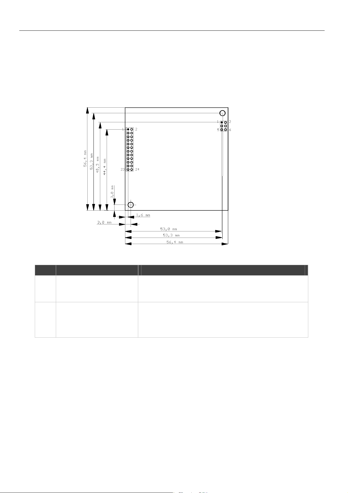
Dimensions (Length x Width x Height) 56.4 mm x 56.4 mm x 14,6 mm
Height of the terminal strip above
PCB
PCB thickness 1.6 mm
Temperature range 0°C – 70°C
Maximum permissible humidity 95% non-condensing
Table 1: Physical Features
approx. 160 mA
approx. 50 mA
6.5 mm
6

i-modul Modem 144/56k Technical Data
1.2 Technological Features
Technological Feature Description
Supported data compression standards
MNP 2/3, MNP 5, V.42 bis; V.44, MNP
10, MNP 10 EC
Fax class Fax Class 1
Modulation types Bell Norm 103/212, V.32bis, V.32, V.23,
V.22, V22 bis, V21, (for 56k version
additionally V.34+, V.34, V.90 and V.92)
Error correction standards V.42, MNP4, LAPM
Table 2: Technological Features
7
Connections i-modul Modem 144/56k
2 Connections
2.1 PCB Layout
P2
P1
Figure 1: PCB layout, terminal strip and fixing hole position
Item Type Description
P1 SAMTEC TW series 2-row
2 mm pitch or Fischer SLY
81 24 Z
P2 SAMTEC TW series 2-row
2 mm pitch or
Plastron PQFZ-06S-VK-024
or Fischer SLY 6
Table 3: Specification and assignment of the terminal strips
Serial interface, inputs and outputs
Phone network interface
8

i-modul Modem 144/56k Connections
2.2 Pin Layout Terminal Strip P1
Pin Type Signal Description
1 GND Ground of supply voltage (ground)
2 Supply VCC 5 V DC supply voltage (or 3,3 V)
3 GND Ground of supply voltage (ground)
4 Input TXD Terminal transmit signal of RS232 line; TTL level
5 GND Ground of supply voltage (ground)
6 Output RXD Receive signal of RS232 line; TTL level
7 Output ID-PIN2 Ground
8 Input RTS~ Request to Send; TTL level (RS232 signal)
9 Output ID-PIN1 GND
10 Output CTS~ Clear To Send; TTL level (RS232 signal)
11 Input RESET~ RESET, TTL level, t
12 Input DTR~ Data Terminal Ready; TTL level (RS232 signal)
13 Output OH~ Off Hook
14 Output DCD~ Data Carrier Detect; TTL level (RS232 signal)
15 Output RI~ Ring Signal TTL level (RS232 signal)
16 Output DSR~ Data Set Ready; TTL level (RS232 signal)
17 Internal connection, do not use
18 Internal connection, do not use
19 Internal connection, do not use
20 Internal connection, do not use
21 GND Ground
22 Internal connection, do not use
23 Internal connection, do not use
24 GND Ground
Table 4: Terminal strip connections description, terminal strip P1
= 0.1 s
min
The tilde "~" behind the signal description indicates that this signal is
"low active".
2.3 Pin Layout Terminal Strip P2
Pin Signal Description
1 Phone signal b1 Outgoing phone line (exchange line or PABX)
2 Phone signal b2 Telephone connected in series
3 Phone signal a1 Incoming phone line (exchange line or PABX)
4 Phone signal a2 Telephone connected in series
5 External bell W Not connected
6 Earth E Not connected
Table 5: Terminal strip connections description, terminal strip P2
9
Connections i-modul Modem 144/56k
2.4 PIN specifications
All following specifications are based on a supply voltage of VCC = 5 V ± 5%. High =
VIH; Low = VIL (refer to Technical Data).
2.4.1 Reset Input
Pin Signal Type Description
11 Reset~ Input Normal state: 1 (internal pull-up resistor)
Reset: 0 (against GND)
A minimum time of 0.1 s for activation is recommended to trigger the
reset safely.
Table 6: PIN specifications - reset input
2.4.2 Indication Signals
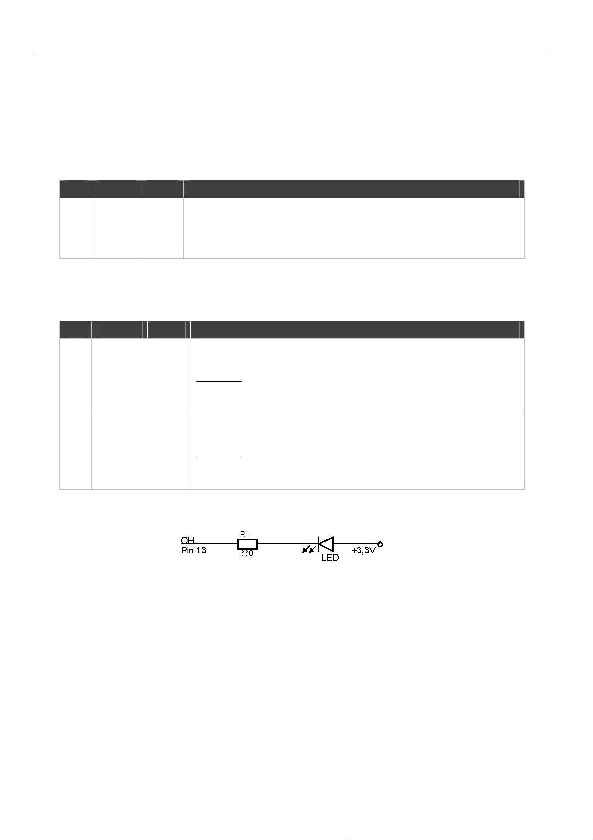
Pin Signal Type Description
13 OH~ Output This output indicates Off-Hook of the modem.
Signaling:
Normal state: High (hung up)
Off-Hook: Low (off-hook)
15 RI~ Output The ring indicator indicates an incoming connection attempt.
Signaling:
Normal state: High
Ring: Low
Table 7: PIN specifications - indication signals
Figure 2: Connection example of the OH signal
10

i-modul Modem 144/56k Connections
2.5 Connection Example for Serial Interface
The following example is only valid for a power supply with VCC = 5 V.
Figure 3: Connection example of the serial interface (5 V VCC)
11

Function Overview i-modul Modem 144/56k
3 Function Overview
The i-modul Modem 144/56k 3.0 basic provides you with the following functions:
Automatic Baud Rate Detection
The i-modul Modem 144/56k 3.0 basic will automatically adjust the
data transmission rate, if a connection is made via its serial interface.
The serial transmission rate can be preset for applications for the
serial communication to be able to initialize with a defined baud rate.
Data buffering for serial data transmission
The i-modul Modem 144/56k 3.0 basic provides rapid send and
receive buffers to adjust the modem to the data processing speed of
the application.
Bit direct mode
The i-modul Modem 144/56k 3.0 basic can forward incoming data
without having any influence on their transmission format.
Hardware and software data flow control
The i-modul Modem 144/56k 3.0 basic can signal the application via
the control lines of the serial interface to interrupt the data flow, if the
buffers of the i-modul Modem 144/56k 3.0 basic exceed a certain
level. An application can also prompt the i-modul Modem 144/56k 3.0
basic via a control line to interrupt the data flow. As an alternative, the
i-modul Modem 144/56k 3.0 basic can control the data flow via
XOFF/XON characters in the data stream.
Error correction / data compression
The i-modul Modem 144/56k 3.0 basic provides the following error
correction and compression protocols: V.42, V.42bis, V.44, MNP2,
MNP3, MNP4 and MNP10
Storing the settings in the user profiles
The i-modul Modem 144/56k 3.0 basic can store the user settings in
two different "profiles". This means that two different configurations
can be stored for special purposes and loaded as needed.
12

i-modul Modem 144/56k Meaning of the Symbols and the Formatting in this
4 Meaning of the Symbols and the Formatting in
this Manual
This section describes the definition, formatting and symbols used in this manual.
The various symbols are meant to help you read and find the information relevant
to you. The following text is structured like a typical operating instruction of this
manual.
Bold print: This will tell you what the following steps will result in
After that, there will be a detailed explanation why you could perform the
following steps to be able to reach the objective indicated first. You can
decide whether the section is relevant for you or not.
An arrow will indicate prerequisites which must be fulfilled to be able to
process the subsequent steps in a meaningful way. You will also learn
which software or which equipment you will need.
1. One individual action step: This tells you what you need to do at this
point. The steps are numbered for better orientation.
A result which you will receive after performing a step will be marked
with a check mark. At this point, you can check if the previous steps
were successful.
Additional information which you should consider are marked with a
circled "i". At this point, we will indicate possible error sources and tell
you how to avoid them.
Alternative results and steps are marked with an arrow. This will tell
you how to reach the same results performing different steps, or what
you could do if you didn't reach the expected results at this point.
13

Operating Principle i-modul Modem 144/56k
5 Operating Principle
This chapter describes the basic procedures to operate and configure an i-modul
Modem 144/56k 3.0 basic. In general, the i-modul Modem 144/56k 3.0 basic is
configured and operated via AT commands. You can enter these commands
yourself with the help of a terminal program and the AT command reference.
5.1 Operation with the Terminal Program
In general, any terminal program can be used. We recommend the program
TeraTerm by T. Teranishi under Windows. It is available free of cost on the
Internet at http://hp.vector.co.jp/authors/VA002416/teraterm.html. You can
use the program "minicom" if you work in a Linux environment.
Caution!
Damage of the serial interface!
A possible direct connection of the serial interface of the imodul Modem 144/56k 3.0 basic with a typical RS232
Configuring and operating the i-modul Modem 144/56k 3.0 basic with a terminal
program
interface of a PC overloads components of the module due
to the higher voltage levels.
Use an RS232 level converter (e.g. MAX232) to adjust both
interface types correctly.
How to configure and operate the i-modul Modem 144/56k 3.0 basic with a
terminal program.
The i-modul Modem 144/56k 3.0 basic is connected to the PC and supplied
with power.
A terminal program is installed on the PC.
1. Start your terminal program.
2. Select the serial port, to which your i-modul Modem 144/56k 3.0
basic is connected.
COM1 under Windows corresponds to /dev/ttyS0 under Linux.
3. Type the character string AT into the terminal program. Complete the
entry by pressing the Enter key.
Each command input starts with AT and is completed with the Enter
key.
14

i-modul Modem 144/56k Operating Principle
The i-modul Modem 144/56k 3.0 basic replies with
OK.
If the i-modul Modem 144/56k 3.0 basic does not respond, this may
have three probable reasons:
a) the i-modul Modem 144/56k 3.0 basic is switched off or
b) the i-modul Modem 144/56k 3.0 basic is not in configuration mode
or
c) the i-modul Modem 144/56k 3.0 basic is connected to another serial
port. Check it and repeat step 3.
4. Configure the i-modul Modem 144/56k 3.0 basic using AT commands.
A reference of the AT commands can be found in the chapter "AT
Command Reference".
5. Save your entries with AT&W.
Not all configurations at the i-modul Modem 144/56k 3.0 basic need to
be saved actively by entering AT&W. Some settings are automatically
saved immediately. We still recommend sending the command AT&W
to the i-modul Modem 144/56k 3.0 basic as your last configuration
step to ensure that all settings are stored safely and are available for
the next restart.
15

Functions i-modul Modem 144/56k
6 Functions
6.1 Automatic Baud Rate Detection
6.1.1 Serial Connection
The automatic baud rate detection enables a continuous automatic adjustment of
all parameters (baud rate, data format) of the serial interface at the i-modul Modem
144/56k 3.0 basic. The device will detect during the operation, which baud rate and
which data format is applied to the serial interface. After a restart, the i-modul
Modem 144/56k 3.0 basic will restore the last working interface configuration.
With each incoming AT command (according to the character string "AT"), the
parameters for the interface of the i-modul Modem 144/56k 3.0 basic will be
checked and adjusted, if necessary. This is the reason why the baud rate can not
be stored with the command AT&W, as the i-modul Modem 144/56k 3.0 basic will
immediately adjust its interface to the current parameters of the currently
established serial connection.
The function is active as default.
Configuration with AT commands
To set the baud rates temporarily (until the
next "AT"), enter one of the following baud
rates for <n>:
300, 600, 1200, 2400, 4800, 9600, 14400,
19200, 28800, 38400, 57600 or 115200
bps.
This setting can not be stored.
The i-modul Modem 144/56k 3.0 basic must be configured with the baud
rate, which is used to operate the application at a later time, as the imodul Modem 144/56k 3.0 basic will always use the last known
functioning configuration of its interface.
AT+IPR=<n>
16
i-modul Modem 144/56k Functions
6.1.2 Phone connection
The automatic negotiation of the baud rate and the modulation standard enables
the i-modul Modem 144/56k 3.0 basic to negotiate the largest possible connection
speed to the remote terminal while the connection is established. The speed
depends on the settings and the abilities of the modem at the remote terminal. Via
the modulation standard, the connection speed can be set through the phone line.
If nothing is defined, the i-modul Modem 144/56k 3.0 basic will automatically try to
determine the optimum connection parameters.
The function is active as default.
Configuration with AT commands
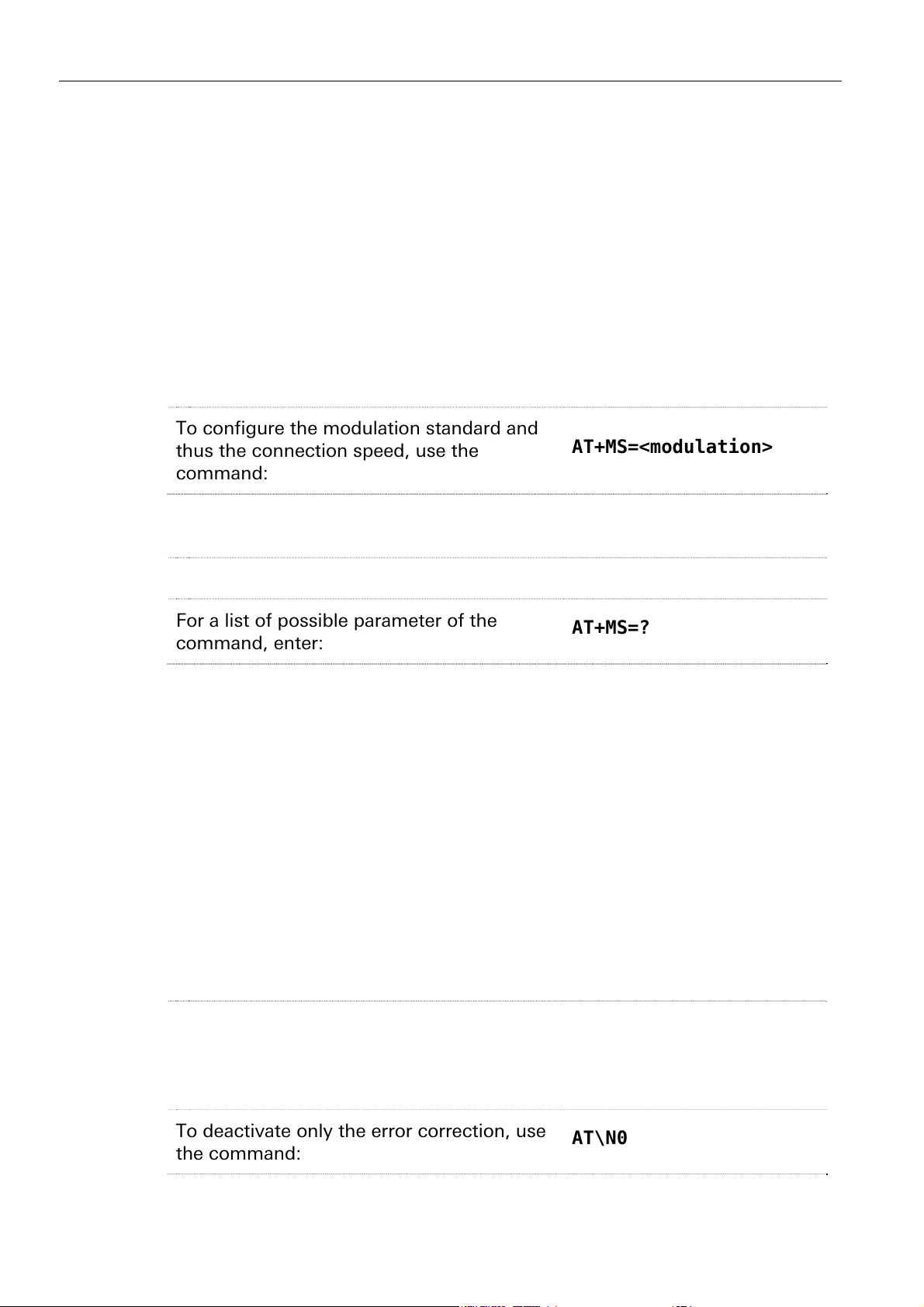
To configure the modulation standard and
thus the connection speed, use the
command:
Please find the possible parameters for this command in the Chapter "AT
Command reference".
AT+MS=<modulation>
To display the current settings:
For a list of possible parameter of the
AT+MS?
AT+MS=?
command, enter:
6.2 Data Buffer for Serial Data Transmission
The i-modul Modem 144/56k 3.0 basic provides send and receive buffers. These
buffers prevent the loss of data, in case the application or the remote terminal can
not receive data at this time. The data buffer can be deactivated together with the
error correction (bit direct mode). When the buffer is activated, the data flow
control should be active to avoid a buffer overflow in the i-modul Modem 144/56k
3.0 basic. If the buffer overflows, the data gets lost. Operation without a buffer and
error correction is only useful for special character framings.
The function is active as default.
Configuration with AT commands
To deactivate the error correction as well as
the buffer in the i-modul Modem 144/56k
3.0 basic for applications with special data
format, use the command:
AT\N1
To deactivate only the error correction, use
AT\N0
the command:
17
Functions i-modul Modem 144/56k
6.3 Bit Direct Mode
For special applications, the buffering of the i-modul Modem 144/56k 3.0 basic can
be deactivated using the setting "unbuffered, bit direct". All data is forwarded
without buffering and further influence of the i-modul Modem 144/56k 3.0 basic.
This applies especially to the parity and stop bits. The error correction and the data
compression are in this case switched off as well. If the i-modul Modem 144/56k
3.0 basic is operated in this mode, not all functions will be available. The remote
configuration and all functions for which a password is required, will no longer be
available. This mode should only be used for special character framings.
Configuration with AT commands
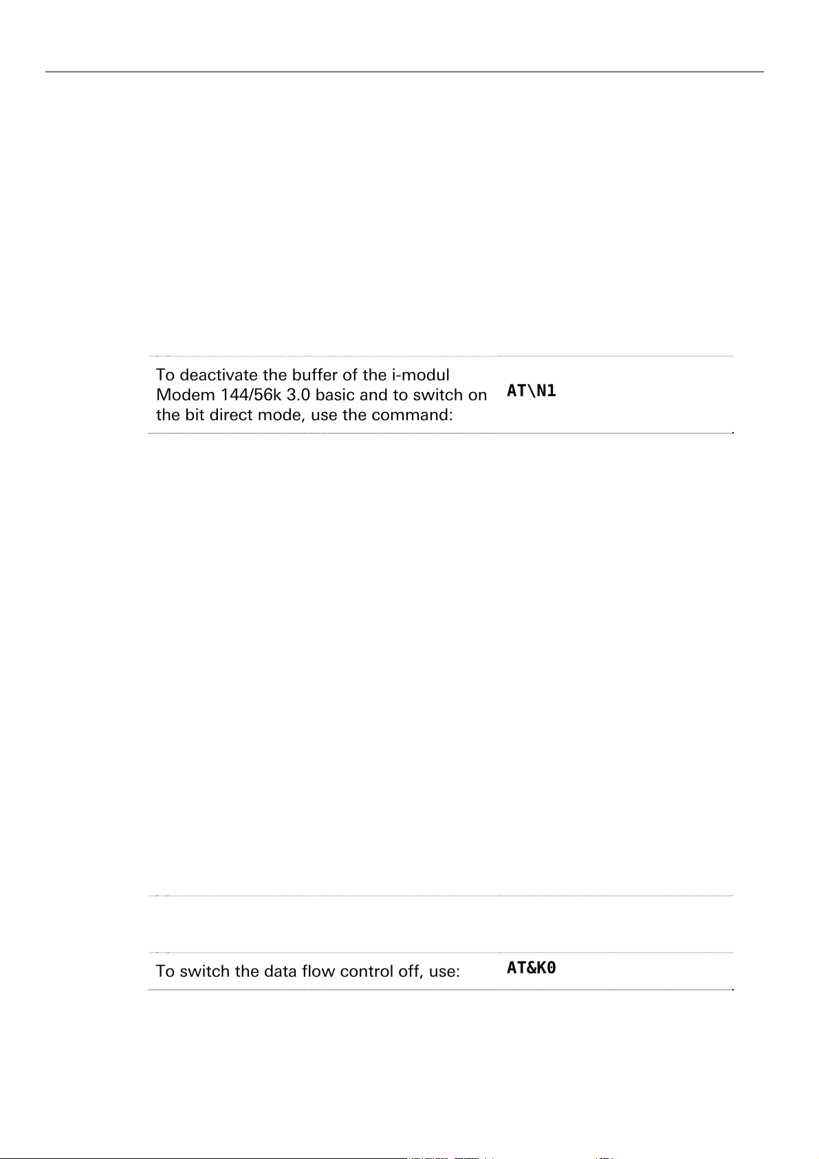
To deactivate the buffer of the i-modul
Modem 144/56k 3.0 basic and to switch on
the bit direct mode, use the command:
AT\N1
6.4 Data Flow Control (Handshake)
The data flow control ensures that the data transfer is interrupted as soon as the
modem buffer exceeds a certain level. Two data flow control options are available:
Via the control lines RTS and CTS, or via the control characters XON/XOFF which
are inserted into the data stream.
6.4.1 Hardware data flow control (RTS/CTS)
The hardware data flow control works in two directions. When the critical buffer
level is exceeded, the modem will set the CTS line to "low" and will thus indicate to
the application to interrupt the dataflow. When the buffer is emptied sufficiently for
the i-modul Modem 144/56k 3.0 basic to be able to receive data again, the CTS line
is set to "high". Reversely, the application can also indicate to the i-modul Modem
144/56k 3.0 basic to interrupt the data flow. This is done via the RTS line. If it is set
to "low", the modem will interrupt the data flow to the application. The application
will set it to "high" to request data from the i-modul Modem 144/56k 3.0 basic.
The data flow control with RTS/CTS behavior is active by default.
Configuration with AT commands
To switch the data flow control on and to
set the type to RTS/CTS, use:
To switch the data flow control off, use:
18
AT&K3
AT&K0
i-modul Modem 144/56k Functions
6.4.2 Software data flow control (XON/XOFF)
When the input buffer of the modem exceeds a certain fill state, the modem will
insert an XOFF character into the data stream to the application. This character will
cause the application to send no more data. It will depend on the according
application software if the XON/XOFF data flow control is supported.
After the input buffer of the modem is emptied so much that data can be received
again, the modem will send an XON character to the application. This character will
cause the application to send data to the modem again. Analogously, the
application can insert XON/XOFF characters into the data stream to switch the data
flow on and off. The XON/XOFF data flow control is only available when the
transmitted data do not contain the characters XON or XOFF, which usually appear
only in actual ASCII texts (7 bit). When binary data (programs, etc.) are transmitted,
or in the XMODEM transmission protocol, for example, occasionally appearing
XON or XOFF characters would disturb the operation.
Configuration with AT commands
To switch the data flow control on and to
AT&K4
set the type to XON/XOFF, use:
To switch the data flow control off, use:
AT&K0
19
 Loading...