

insys icom GSM 4.3, GSM 4.3 compact User Manual
INSYS GSM 4.3
Manual


Copyright © August 11 INSYS MICROELECTRONICS GmbH
Any duplication of this manual is prohibited. All rights on this documentation and
the devices are with INSYS MICROELECTRONICS GmbH Regensburg.
Trademarks
The use of a trademark not shown below is not an indication that it is freely avail-
able for use.
MNP is a registered trademark of Microcom Inc.
IBM PC, AT, XT are registered trademarks of International Business Machine Corporation.
INSYS®, e-Mobility LSG® and e-Mobility PLC® are registered trademarks of INSYS
MICROELECTRONICS GmbH.
Windows™ is a registered trademark of Microsoft Corporation.
Linux is a registered trademark of Linus Torvalds.
Publisher:
INSYS MICROELECTRONICS GmbH
Waffnergasse 8
D-93047 Regensburg, Germany
Phone: +49 (0)941/56 00 61
Fax: +49 (0)941/56 34 71
E-mail: insys@insys-tec.de
Internet: http://www.insys-icom.com
Date: Aug-11
Item: 31-22-03.153
Version: 1.2
Language: EN

Content
1 Preface.....................................................................................................7
1.1 Defects Liability Terms ..........................................................................................7
1.2 Marking of Warnings and Notes............................................................................ 8
1.2.1 Symbols and Key Words.......................................................................... 8
1.3 Symbols and the Formatting in this Manual ..........................................................9
2 Safety.....................................................................................................10
2.1 Usage According to the Regulations ...................................................................10
2.2 Permissible Technical Limits................................................................................11
2.3 Responsibilities of the Operator........................................................................... 11
2.4 Qualification of the Personnel..............................................................................11
2.5 Instructions for Transport and Storage ................................................................11
2.6 Markings on the Product ..................................................................................... 12
2.7 Environmental Protection ....................................................................................12
2.8 Safety Instructions for Electrical Installation........................................................ 13
2.9 General Safety Instructions..................................................................................13
3 Scope of Delivery...................................................................................15
4 General ..................................................................................................16
5 Functional Overview ..............................................................................17
6 Technical Data .......................................................................................20
6.1 Physical Features.................................................................................................20
6.2 Technological Features........................................................................................21
7 Display and Control Elements ................................................................ 22
7.1 Meaning of the Displays ......................................................................................24
7.2 Function of the Control Elements ........................................................................ 25
8 Connections...........................................................................................26
8.1 Front Panel Connections......................................................................................26
8.2 Terminal Connections on the Top........................................................................27
8.3 Terminal Connections on the Bottom .................................................................. 28
8.4 Pin Assignment of the Serial Interface.................................................................29
8.5 Audio Connection (not INSYS GSM 4.3 compact) ............................................... 29
9 Mounting ...............................................................................................30
10 Initial Operation...................................................................................... 34
11 Operating Principle ................................................................................36
11.1 Operation via Terminal Program ..........................................................................36
11.2 Operation via SMS............................................................................................... 37
11.3 Operation with HSComm GSM............................................................................38
4 Aug-11

Contents
12 Functions ...............................................................................................40
12.1 Entering the PIN of the SIM Card ........................................................................40
12.2 Inserting and Removing the SIM Card.................................................................42
12.3 Checking the Status of the GSM Login................................................................44
12.4 Checking the Signal Field Strength of the Mobile Phone Network ......................45
12.5 Configure Serial Interface .................................................................................... 46
12.6 Data Flow Control (Handshake) ...........................................................................47
12.6.1 Hardware Data Flow Control (RTS/CTS)................................................. 47
12.6.2 Software Data Flow Control (XON/XOFF) .............................................. 48
12.7 Configure Date and Time.....................................................................................49
12.8 Configure Dial-Up Attempts for Message Dispatch.............................................50
12.9 Configure Scheduled Logout/Login ..................................................................... 50
12.10 Establishing or Accepting a Data Connection......................................................52
12.11 Establish Voice Connection (not INSYS GSM 4.3 compact) ................................54
12.12 Using USSD Codes..............................................................................................54
12.13 Idle Connection Control with Data Transmit Control ...........................................55
12.14 Automatic Call Acceptance..................................................................................56
12.15 Selective Call Acceptance....................................................................................56
12.16 Configure Security Callback.................................................................................58
12.17 Alarm Inputs ........................................................................................................60
12.18 Configure Alarms.................................................................................................61
12.19 Switching Outputs...............................................................................................64
12.19.1 SWITCH Command for Controlling the Control Outputs ....................... 66
12.20 Activate Switching / Querying of the Outputs / Inputs via DTMF ........................67
12.21 Switching the Outputs / Querying the Inputs via DTMF ......................................70
12.22 Remote Configuration of the INSYS GSM 4.3 .....................................................73
12.23 Configure Remote Configuration via SMS...........................................................76
12.24 Configure Periodic Alive Message .......................................................................78
12.25 Configure Power-Up SMS ...................................................................................79
12.26 Manual Sending of Messages..............................................................................80
12.27 Operation with a PLC........................................................................................... 80
12.28 Event History ....................................................................................................... 81
12.29 Reset of the Device..............................................................................................83
12.30 Firmware Update.................................................................................................84
13 Firmware History ...................................................................................86
14 Maintenance, Repair and Troubleshooting.............................................87
14.1 Maintenance........................................................................................................87
14.2 Troubleshooting...................................................................................................87
14.3 Repair ..................................................................................................................87
Aug-11 5

Content
15 GSM Service Center Numbers ............................................................... 88
16 Waste Disposal ......................................................................................89
16.1 Repurchasing of Legacy Systems........................................................................89
17 Declaration of Conformity ...................................................................... 90
18 Tables and Diagrams..............................................................................91
18.1 List of Tables .......................................................................................................91
18.2 List of Diagrams ..................................................................................................91
19 Index ......................................................................................................92
6 Aug-11

INSYS GSM 4.3 Preface
1 Preface
This manual allows for the safe and efficient use of the product. The manual is part
of the product and must always be stored accessible for installation, commissioning and operating personnel.
1.1 Defects Liability Terms
A usage not according to the intended purpose, an ignorance of this documentation, the use of insufficiently qualified personnel as well as unauthorised modifications exclude the liability of the manufacturer for damages resulting from this. The
liability of the manufacturer ceases to exist.
The regulations of our Delivery and Purchasing Conditions are effective. These can
be found on our website (www.insys-icom.de/imprint/) under “General Terms and
Conditions“.
7

Preface INSYS GSM 4.3
1.2 Marking of Warnings and Notes
1.2.1 Symbols and Key Words
Danger!
Risk of severe or fatal injury
One of these symbols in conjunction with the key word
Danger indicates an imminent danger. It will cause death or
severe injuries if not avoided.
Warning!
Personal injury
This symbol in conjunction with the key word Warning indicates a possibly hazardous situation. It might cause death
or severe injuries if not avoided.
Caution!
Slight injury and / or material damage
This symbol in conjunction with the key word Caution indicates a possibly hazardous or harmful situation. It might
cause slight or minor injuries or a damage of the product or
something in its vicinity if not avoided.
Note
Improvement of the application
This symbol in conjunction with the key word Note indicates hints for the user or very useful information. This information helps with installation, set-up and operation of
the product to ensure a fault-free operation.
8

INSYS GSM 4.3 Preface
1.3 Symbols and the Formatting in this Manual
This section describes the definition, formatting and symbols used in this manual.
The various symbols are meant to help you read and find the information relevant
to you. The following text is structured like a typical operating instruction of this
manual.
Bold print: This will tell you what the following steps will result in
After that, there will be a detailed explanation why you could perform the
following steps to be able to reach the objective indicated first. You can decide whether the section is relevant for you or not.
An arrow will indicate prerequisites which must be fulfilled to be able to
process the subsequent steps in a meaningful way. You will also learn
which software or which equipment you will need.
1. One individual action step: This tells you what you need to do at this point.
The steps are numbered for better orientation.
A result which you will receive after performing a step will be marked
with a check mark. At this point, you can check if the previous steps
were successful.
Additional information which you should consider are marked with a
circled "i". At this point, we will indicate possible error sources and tell
you how to avoid them.
Alternative results and steps are marked with an arrow. This will tell
you how to reach the same results performing different steps, or what
you could do if you didn't reach the expected results at this point.
9

Safety INSYS GSM 4.3
2 Safety
The Safety section provides an overview about the safety instructions, which must
be observed for the operation of the product.
The product is constructed according to the currently valid state-of-the-art technology and reliable in operation. It has been checked and left the factory in flawless
condition concerning safety. In order to maintain this condition during the service
life, the instructions of the valid publications and certificates must be observed and
followed.
It is necessary to adhere to the general safety instructions must when operating the
product. The descriptions of processes and operation procedures are provided with
precise safety instructions in the respective sections in addition to the general
safety instructions.
Moreover, the local accident prevention regulations and general safety regulations
for the operating conditions of the device are effective.
An optimum protection of the personnel and the environment from hazards as well
as a safe and fault-free operation of the product is only possible if all safety instructions are observed.
2.1 Usage According to the Regulations
The product may only be used for the purposes specified in the function overview.
In addition, it may be used for the following purposes:
Usage and mounting in an industrial cabinet.
Switching and data transmission functions in machines according to
the machine directive 2006/42/EC.
Usage as data transmission device for a PLC.
The product may not be used for the following purposes and used or operated under the following conditions:
Controlling or switching of machines and systems, which do not
comply with the directive 2006/42/EC.
Usage, controlling, switching and data transmission of machines and
systems, which are operated in explosive atmospheres.
Controlling, switching and data transmission of machines, which may
involve risks to life and limb due to their functions or when a breakdown occurs.
10

INSYS GSM 4.3 Safety
2.2 Permissible Technical Limits
The product is only intended for the use within the permissible technical limits
specified in the data sheets.
The following permissible limits must be observed:
The ambient temperature limits must not be fallen below or ex-
ceeded.
The supply voltage range must not be fallen below or exceeded.
The maximum humidity must not be exceeded and condensate for-
mation must be prevented.
The maximum switching voltage and the maximum switching current
load must not be exceeded.
The maximum input voltage and the maximum input current must not
be exceeded.
2.3 Responsibilities of the Operator
As a matter of principle, the operator must observe the legal regulations, which are
valid in his country, concerning operation, functional test, repair and maintenance
of electrical devices.
2.4 Qualification of the Personnel
The installation, commissioning and maintenance of the product must only be performed by trained expert personnel, which has been authorised by the plant operator. The expert personnel must have read and understood this documentation and
observe the instructions.
Electrical connection and commissioning must only be performed by a person, who
is able to work on electrical installations and identify and avoid possible hazards
independently, based on professional training, knowledge and experience as well
as knowledge of the relevant standards and regulations.
2.5 Instructions for Transport and Storage
The following instructions must be observed:
Do not expose the product to moisture and other potential hazardous
environmental conditions (radiation, gases, etc.) during transport and
storage. Pack product accordingly.
Pack product sufficiently to protect it against shocks during transport
and storage, e.g. using air-cushioned packing material.
Check product for possible damages, which might have been caused by improper
transport, before installation. Transport damages must be noted down to the shipping documents. All claims or damages must be filed immediately and before installation against the carrier or party responsible for the storage.
11
Safety INSYS GSM 4.3
2.6 Markings on the Product
The identification plate of the product is either a print or a label on a face of the
product. Amongst other things, it contains the following markings, which are explained in detail here.
Observe manual
This symbol indicates that the manual of the product contains essential safety instructions that must be followed
implicitly.
Dispose waste electronic equipment environmentally
This symbol indicates that waste electronic equipment
must be disposed separately from residual waste via appropriate collecting points. See also Section Disposal in this
manual.
CE marking
By applying a CE marking, the manufacturer confirms that
the product complies with the European directives that apply product-specific.
Appliance Class II – double insulated
This symbol indicates that the product complies with Appliance Class II
2.7 Environmental Protection
Dispose the product and the packaging according to the relevant environmental
protection regulations. The Waste Disposal section in this manual contains notes
about disposing the product. Separate the packaging components of cardboard
and paper as well as plastic and deliver them to the respective collection systems
for recycling.
12
INSYS GSM 4.3 Safety
2.8 Safety Instructions for Electrical Installation
The electrical connection must only be made by authorised expert personnel according to the wiring diagrams.
The notes to the electrical connection in the manual must be observed. Otherwise,
the protection category might be affected.
The safe disconnection of circuits, which are hazardous when touched, is only ensured if the connected devices meet the requirements of VDE T.101 (Basic requirements for safe disconnection).
The supply lines are to be routed apart from circuits, which are hazardous when
touched, or isolated additionally for a safe disconnection.
2.9 General Safety Instructions
Caution!
Moisture and liquids from the environment may seep into
the interior of the product!
Fire hazard and damage of the product.
The product must not be used in wet or damp environments, or in the direct vicinity of water. Install the product
at a dry location, protected from water spray. Disconnect
the power supply before you perform any work on a device
which may have been in contact with moisture.
Caution!
Short circuits and damage due to improper repairs and
modifications as well as opening of maintenance areas.
Fire hazard and damage of the product.
It is not permitted to open the product for repair or modification.
Caution!
Overcurrent of the device supply!
Fire hazard and damage of the product due to overcurrent.
The product must be secured with a suitable fuse against
currents exceeding 1.6 A.
13

Safety INSYS GSM 4.3
Caution!
Overvoltage and voltage peaks from the mains supply!
Fire hazard and damage of the product due to overvoltage.
Install suitable overvoltage protection.
Caution!
Damage due to chemicals!
Ketones and chlorinated hydrocarbons dissolve the plastic
housing and damage the surface of the device.
Never let the device come into contact with ketones (e.g.
acetone) or chlorinated hydrocarbons, such as dichloromethane.
Caution!
Antenna distance to persons!
A too close distance of GSM antennas to persons may affect the health.
Please observe that a minimum distance of 20 cm between
a GSM antenna and a person must be maintained during
operation.
Note
Restrictions within the area of validity of the FCC!
Possible loss of the FCC approval.
Please observe that further approvals for the terminal device are required in the area of validity of the FCC if you use
aerials with a gain of more than 8.41 dBi (GSM 1900 MHz)
or 2.98 dBi (GSM 850 MHz) as well as when designing devices, which use other wireless communications besides
GSM/GPRS (e.g. WLAN or ISM radio).
We are ready to offer consultation for further approval requirements in countries outside the EC.
14

INSYS GSM 4.3 Scope of Delivery
3 Scope of Delivery
The scope of delivery for the INSYS GSM 4.3 includes all accessories listed below.
Please check if all accessories are included in the box. If a part is missing or damaged, please contact your distributor.
INSYS GSM 4.3
Cable:
1 serial cable with 9-pin D-Sub connector for the connection to the PC
1 manual
Optional Accessories
CD-ROM
GSM antenna
Outside mounted antenna, magnetic base antenna or patch antenna
Configuration software HSComm
AT Command Reference
15

General INSYS GSM 4.3
4 General
The INSYS GSM 4.3 is available in two versions. These are
INSYS GSM 4.3
INSYS GSM 4.3 compact
The INSYS GSM 4.3 differs by a compact design housing for in-wall connection
boxes and the missing audio interface from the INSYS GSM 4.3. Both versions are
referred to as INSYS GSM 4.3 in the further course of this manual. If the INSYS
GSM 4.3 compact differs from the INSYS GSM 4.3, this will be mentioned in particular in the respective sections.
16

INSYS GSM 4.3 Functional Overview
5 Functional Overview
The INSYS GSM 4.3 offers the following functions:
Data buffer for serial data transmission
The INSYS GSM 4.3 has a fast send and receive buffer (cache) to ad-
just the modem to the operating speed of the application.
Hardware and software data flow control
The INSYS GSM 4.3 can transmit to the application via the control
lines of the serial interface to interrupt the dataflow, if the buffers of
the INSYS GSM 4.3 exceed a certain level. An application can also
prompt the INSYS GSM 4.3 via a control line to interrupt the data
flow. As an alternative, the INSYS GSM 4.3 can control the data flow
via XOFF/XON characters in the data stream.
Selective call answer
The INSYS GSM 4.3 can be set to accept only calls from phone num-
bers that were previously stored.
Configuration via SMS
Numerous functions of the INSYS GSM 4.3 may be configured via
SMS. This allows a configuration of the INSYS GSM 4.3 without PC
and modem connection.
Comfortable Configuration of the SMS recipients
For each alarm message, which is sent by the INSYS GSM 4.3, up to
10 recipient numbers may be assigned using a matrix. This allows for
the creation of an alarm plan and the targeted notification of service
personnel
Voice functionality (not INSYS GSM 4.3 compact)
The voice functionality allows to establish voice connections with
other phones using a connected phone receiver. This provides an
easy communication with the service personnel at the site.
Automatic call acceptance for voice connections
The INSYS GSM 4.3 enables to accept voice calls automatically. This
allows for an automatic voice connection establishment, e.g. for
emergency call or monitoring purposes.
Remote firmware update
The firmware of the INSYS GSM 4.3 may be updated remotely. The
settings, which are important fort he operation, like the SIM PIN are
maintained with this.
17

Functional Overview INSYS GSM 4.3
Remote configuration
The INSYS GSM 4.3 can be configured remotely with the help of a
common modem and a terminal program.
Sending messages via data connection, SMS or Fax
The INSYS GSM 4.3 can send up to 10 previously entered messages
to any defined recipient via an AT command. The dispatch can also be
triggered by switching the alarm inputs. Several transmission paths
are possible, such as Fax and SMS.
Pulse input to send up to 10 SMS messages
The SMS to a previously defined recipient can be triggered via the
number of pulses at an alarm input.
IO states retrievable via DTMF and SMS
The state of the inputs and outputs may be retrieved remotely with
the help of DTMF digits sent from a common phone or via an SMS
with an AT command. The INSYS GSM 4.3 answers and replies with
the status of the inputs and outputs via signal tones or SMS.
Remote switching of the outputs via DTMF and SMS
The switching outputs at the INSYS GSM 4.3 can be set remotely
with the help of DTMF digits sent from a common phone. The alarm
inputs can be selected via a DTMF phone. Furthermore, the output
may be switched via an AT command received by an SMS.
Switching inputs and alarm outputs for SMS dispatch and to establish
an alarm data connection
The INSYS GSM 4.3 has two potential-free switch outputs, which can
be used to switch other functions in an application. The INSYS GSM
4.3 also has digital switch inputs, which are used to establish connections or to send messages via SMS and fax.
Switching the output via events like level drop at alarm input, GSM
network failure, incoming call or switching on the device
The INSYS GSM 4.3 can change the state of a switching output in
case of events like GSM network failure, incoming call, switching on
the device or connecting the alarm input to ground. This enables your
application to react on these events.
Pulse output via switching outputs
The switching outputs can be opened and closed sequentially. This
enables to output so-called „counting pulses“ at the outputs of the
INSYS GSM 4.3. The INSYS GSM 4.3 can output up to ten pulses per
output.
18

INSYS GSM 4.3 Functional Overview
Access control
The INSYS GSM 4.3 can be protected from unauthorized access via a
phone connection. An incoming connection must first be enabled
with a password. Using security callback, the INSYS GSM 4.3 calls a
previously defined phone number back, when a call comes in.
Idle connection control with Data Transmit Control
Data Transmit Control enables the INSYS GSM 4.3 to terminate the
connection, if no data is transmitted during a defined state. This will
prevent unnecessary costs.
Integrated real-time clock
The integrated real-time clock can be used to send alive messages
time-controlled. Furthermore, the integrated real-time clock allows for
a regular logout and login out of or into the GSM network.
Event history
All occurred events are logged in a history with a maximum capacity
of 200 entries.
New functions of the INSYS GSM 4.3:
Switching the outputs by establishing a modem connection
The INSYS GSM 4.3 can change the state of a switch output by estab-
lishing a modem connection (enabling of the control line DCD). This
enables your application to react on such events. The output will be
reset to its initial state if the connection is released.
Switching the outputs via clear text commands
The INSYS GSM 4.3 allows to assign clear text names (switch alias) to
certain switch operations. These clear text names can easily be used
to switch outputs via SMS or AT command.
Pulsing the outputs via DTMF
The switch outputs at the INSYS GSM 4.3 can also be pulsed re-
motely from a usual telephone by entering DTMF digits now.
Buffering the alarm inputs
Up to 5 alarm messages are buffered at the inputs and processed
consecutively.
Reading out SCN from the SIM card
The SMS Service Center Nummer (SCN) can easily be read out from
the SIM card and stored.
19

Technical Data INSYS GSM 4.3
6 Technical Data
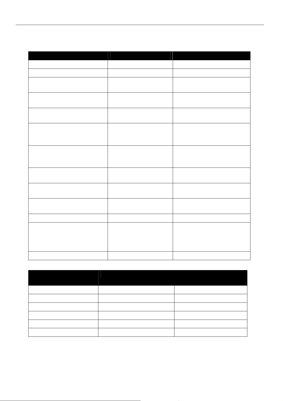
6.1 Physical Features
All specified data was measured with a nominal input voltage, at full load, and an
ambient temperature of 25 °C. The threshold value tolerances are subject to typical
fluctuations.
Physical Feature Value
Operating voltage minimum 10 V DC
maximum 60 V DC
Power input sleep 2 W
Power input connection 2.5 W
Maximum power input (during 577 µs
lasting GSM transmit burst)
Level alarm inputs Level HIGH = 4-12 V
Input current from GND to internal +5 V typically 0.5 mA
Switch output, maximum switch voltage 30 V (DC) / 42 V (AC)
Switch output, maximum current load 1 A (DC) / 0.5 A (AC)
Minimum operating voltage SIM cars 3 V
Emitted radiation:
EGSM 900: Class 4
GSM 1800: Class 1
EGSM 900: Class E2
GSM 1800: Class E2
Weight 270 g (INSYS GSM 4.3)
Dimensions (Width x Depth x Height) 55 x 110 x 75 mm (INSYS GSM 4.3)
10 W
Level LOW = 0-1 V
2 W
1 W
0.5 W
0.5 W
218 g (INSYS GSM 4.3 compact)
82 x 58 x 84 mm (INSYS GSM 4.3
compact)
Temperature range 0 °C – 55 °C (INSYS GSM 4.3)
-20 °C – 55 °C (INSYS GSM 4.3 compact)
Maximum allowed humidity 95% non-condensing
Protection Class Housing IP40, Terminals IP20
Table 1: Physical Features
20

INSYS GSM 4.3 Technical Data
6.2 Technological Features
Technological Feature Description
Data formats of the serial interface 7E1,7O1, 7N2, 8N1, 8E1, 8O1, 8N2,
Supported GSM audio encoding HR,FR,EFR
Fax-Classes Fax Class 1/2
Modulation types V.22bis, V.32, V.34,V.23, V.110
Table 2: Technological Features
21
Display and Control Elements INSYS GSM 4.3
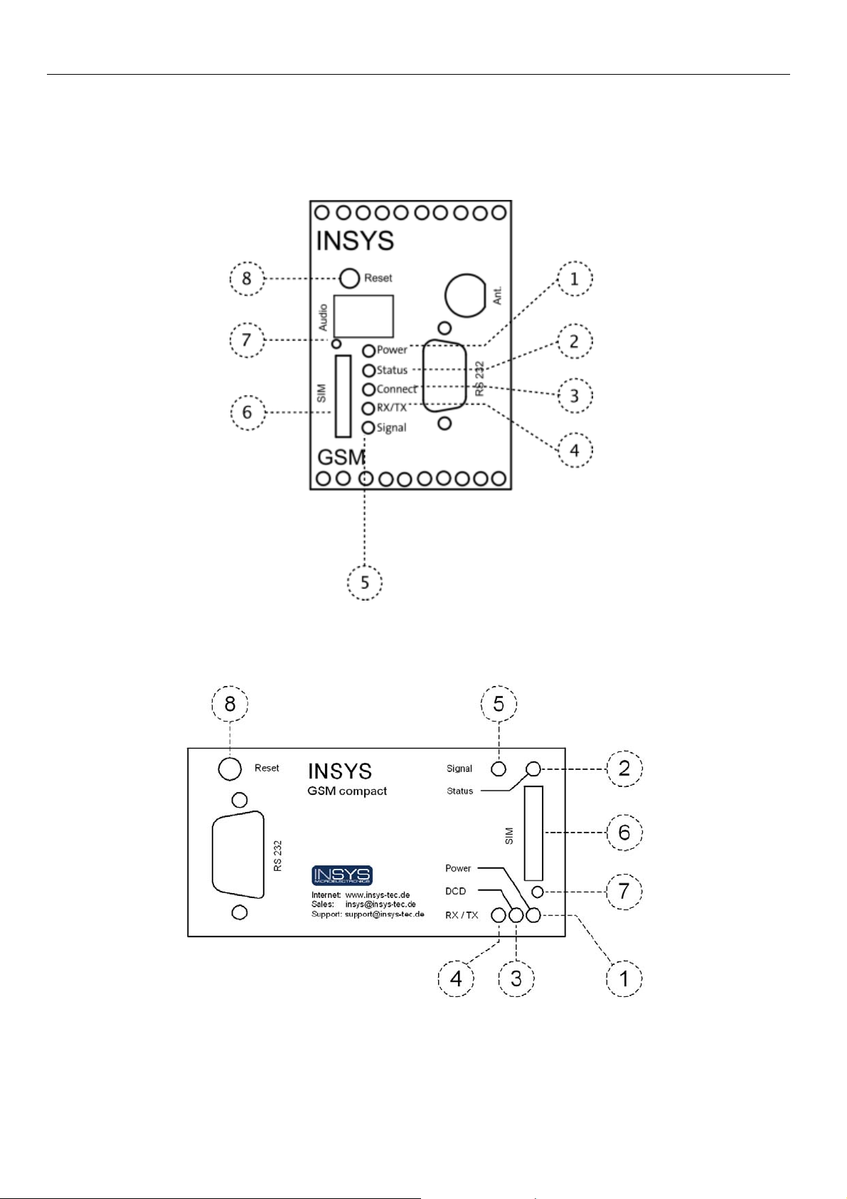
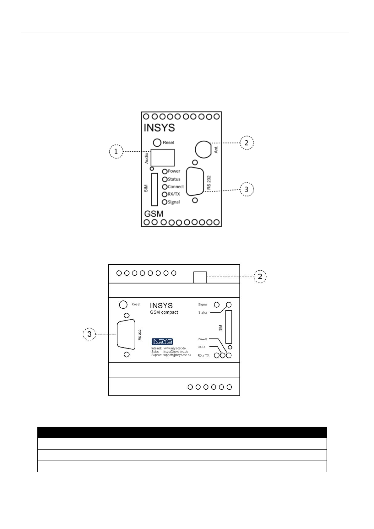
7 Display and Control Elements
Figure 1: Control elements/displays (INSYS GSM 4.3)
Figure 2 Control elements/displays (INSYS GSM 4.3 compact)
22

INSYS GSM 4.3 Display and Control Elements
Position Description
1 Power LED
2 Status LED
3 Connect LED / DCD LED (INSYS GSM 4.3 compact)
4 RX/TX LED
5 Signal LED
6 SIM card holder
7 SIM card holder eject key
8 Reset key
Table 3: Description of the LEDs on the front panel of the device
23
Display and Control Elements INSYS GSM 4.3
7.1 Meaning of the Displays
Description Display Meaning
Power LED LED on Supply voltage available
LED off No supply voltage
Status LED LED on INSYS GSM 4.3 is logged
in into the cellular network
LED flashes Data connection estab-
lished
LED flashes quickly Initialization, SMS dis-
patch, alarm processing
LED off INSYS GSM 4.3 is not
logged in into the cellular
network
Connect LED /
DCD LED (INSYS GSM 4.3
LED on Connection to remote ter-
minal is established
compact)
LED off No connection to remote
terminal
RX/TX LED LED on INSYS GSM 4.3 transmits
data via the serial interface
LED off No data is transmitted via
the serial interface
Signal LED LED on GSM reception perfect
LED flashes Flashing frequency indi-
cates the quality of the
GSM reception (refer to
Table 5).
LED off No GSM reception
Table 4: Meaning of the LED displays
Flashing Rate LED Sig-
Value Signal Quality
nal
Always on 25 .. 31 Optimum
16.7 Hz (very quick) 23 .. 24 Very good
7.1 Hz 21 .. 22
3.8 Hz 19 .. 20 Good
2.6 Hz (slow) 17 .. 18 Poor
off <17 or 99 (not detectable) Insufficient
Table 5: Flashing code of the Signal LED
24

INSYS GSM 4.3 Display and Control Elements
7.2 Function of the Control Elements
Description Operation Meaning
Reset key
Press at least 1 second. Resets the INSYS GSM 4.3
Press at least 25 seconds
(you may release if the
Connect or DCD and
Status LEDs blink alternating).
SIM card holder Eject the card holder with
the card holder eject key
and remove the card
holder, then. Observe the
correct orientation of card
holder and SIM card when
inserting. The contacts of
the SIM card face upwards in the card holder,
The contacts of the SIM
card must face to the left
side of the device when
inserting the card holder.
and restarts it.
Resets the INSYS GSM 4.3
to factory defaults and re-
starts it.
Receives the SIM card.
SIM card holder eject
key
Table 6: Description of the functions and meaning of the control elements
Press the card holder eject
key with a thin tool.
Ejects the SIM card holder
from the housing.
25
Connections INSYS GSM 4.3
8 Connections
8.1 Front Panel Connections
Figure 3: Connections on the front panel of the device (INSYS GSM 4.3)
Figure 4: Connections on the front panel of the device (INSYS GSM 4.3 compact)
Position Description
1 Audio connection (audio socket, not INSYS GSM 4.3 compact)
2 FME aerial socket
3 Serial Interface (RS232 jack)
Table 7: Description of the connections on the front panel of the device
26
INSYS GSM 4.3 Connections
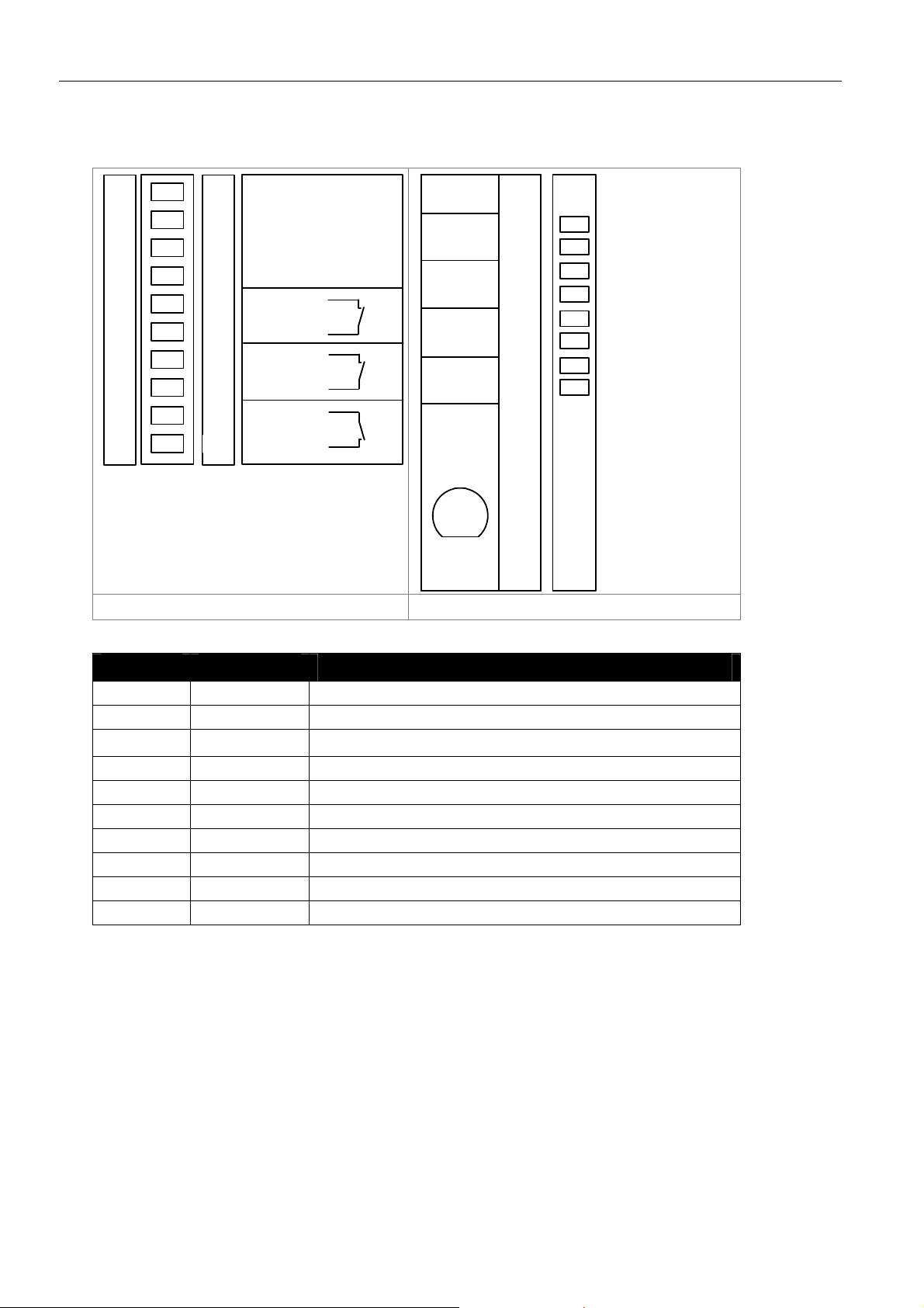
8.2 Terminal Connections on the Top
1
2
3
4
5
6
7
8
9
10
1
2
3
4
5
6
7
8
9
10
GND
X1
10...60 VDC
GND
GND
Reset
GND
Input 1
Input 2
GND
supply
Power
10..60 VDC
GND
GND
Reset
Ext.
IN 1
IN 2
RESET
GND
Input 1
Input 2
GND
Ant.
INSYS GSM 4.2 INSYS GSM 4.2 compact
Figure 5: Connections on the top of the device
Terminal Name Description
1 GND Ground (not INSYS GSM 4.3 compact)
2 X1 Reserved (not INSYS GSM 4.3 compact)
3
4 GND Ground
5 GND Ground
6 Reset Reset input
7 GND Ground
8 Input 1 Alarm input 1
9 Input 2 Alarm input 2
10 GND Ground
Table 8: Description of the connections on the top of the device
10 ... 60VDC Power supply 10V - 60V DC
27
Connections INSYS GSM 4.3
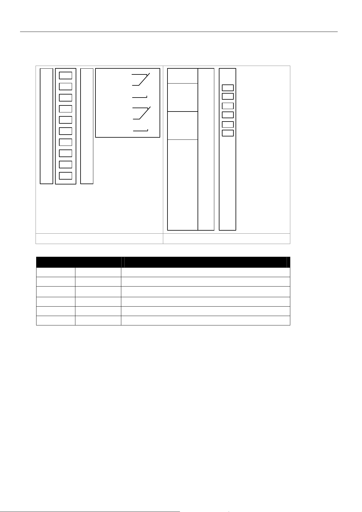
8.3 Terminal Connections on the Bottom
OUT 1-NC
11
12
13
14
15
16
17
11
OUT 1
12
OUT 1-NO
13
OUT 2-NC
14
OUT 2
15
OUT 2-NO
16
17
OUT1-NC
OUT1
OUT1-NO
OUT2-NC
OUT2
OUT2-NO
18
19
20
18
19
20
INSYS GSM 4.2 INSYS GSM 4.2 compact
Figure 6: Description of the connections on the top of the device
Terminal Name Description
11 OUT 1-NC Output 1 normally closed
12 OUT 1 Output 1
13
14 OUT 2-NC Output 2 normally closed
15 OUT 2 Output 2
16 OUT 2-NO Output 2 normally open
Table 9: Connections on the top of the device
OUT 1-NO Output 1 normally open
28
INSYS GSM 4.3 Connections
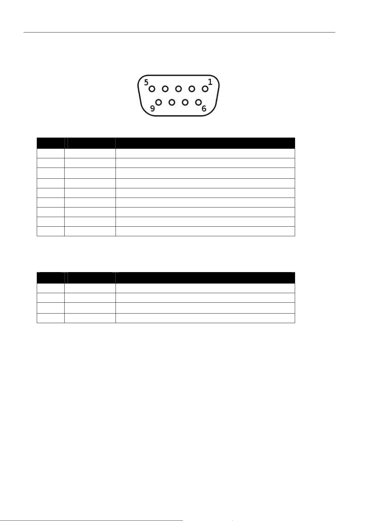
8.4 Pin Assignment of the Serial Interface
Figure 7: 9-pin D-Sub jack at the device
Pin Signal Description
1 DCD Data Carrier Detect
2 RXD Receive Data
3
4 DTR Data Terminal Ready
5 GND Ground
6 DSR Data set ready
7 RTS Request to send
8 CTS Clear To Send
9 RI Ring Indication
Table 10: Description of the pin allocation of the D-Sub jack
TXD Transmit Data
8.5 Audio Connection (not INSYS GSM 4.3 compact)
Pin Signal Description
1 Microphone -
2 Speaker -
3
4 Microphone +
Table 11: Layout of the Western socket
Speaker +
29
 Loading...