

Page 1
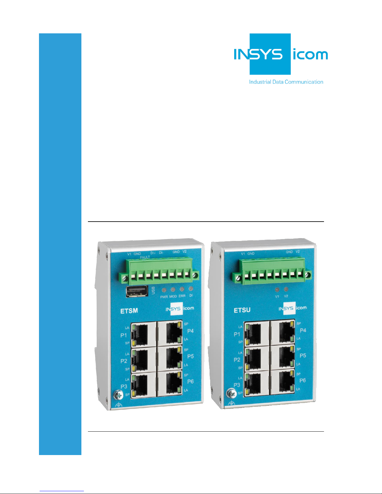
ETSM / ETSU
Installation and
Operation Manual
Manual
Page 2

Page 3

Copyright © July 2018 INSYS MICROELECTRONICS GmbH
Any duplication of this manual is prohibited. All rights on this documentation and
the devices are with INSYS MICROELECTRONICS GmbH Regensburg.
Trademarks
The use of a trademark not shown below is not an indication that it is freely avai la-
ble for use.
MNP is a registered trademark of Microcom Inc.
IBM PC, AT, XT are registered trademarks of International Business Machine Corporation.
INSYS®, VCom®, e-Mobility LSG® and e-Mobility PLC® are registered trademarks of
INSYS MICROELECTRONICS GmbH.
Windows™ is a registered trademark of Microsoft Corporation.
Linux is a registered trademark of Linus Torvalds.
Publisher:
INSYS MICROELECTRONICS GmbH
Hermann-Köhl-Str. 22
D-93049 Regensburg, Germany
Phone: +49 941 58692 0
Fax: +49 941 58692 45
E-mail: info@insys-icom.com
Internet: http://www.insys-icom.com
Date: Jul-18
Item: 10019946
Version: 1.0
Language: EN
Page 4

Content
4
Jul-18
1 Preface ............................................................................... 6
1. 1 Defects Liability Terms....................................................................... 6
1. 2 Feedback ....................................................................................... 6
1. 3 Marking o f Warnings and Notes ........................................................... 7
1. 4 Sy mbols and the Formatting in this Manual ............................................. 8
2 Safety ................................................................................ 9
2. 1 Intended Use .................................................................................. 9
2. 2 Per missible Technical Limits .............................................................. 10
2. 3 Responsibilities of the Operator .......................................................... 10
2. 4 Qualification of the Personnel ............................................................ 10
2. 5 Instructions for Tran sport and Storage.................................................. 10
2. 6 Marking s on the Product .................................................................. 11
2. 7 Environmental Protection ................................................................. 11
2. 8 Safety Instructions for Electrical Installation ........................................... 12
2. 9 General Safety Instructions ............................................................... 12
3 Using Open Source Software .................................................. 14
3. 1 General Infor mation ........................................................................ 14
3. 2 Special Liab ility Regulations .............................................................. 15
3. 3 Used Open -Source So ftware ............................................................. 15
4 Version History ................................................................... 16
5 Device Variants ................................................................... 17
6 Scope of Delivery ................................................................ 18
7 Technical Information ........................................................... 19
7. 1 Technical Data............................................................................... 19
7.1.1 Physical Features ................................................................................ 19
7.1.2 Technologica l Features.........................................................................20
7. 2 Connections and display elements ...................................................... 20
7.2.1 Connecting the connectors ..................................................................23
8 Assembly .......................................................................... 24
9 Commissioni ng, Operation and Configuration ETSU....................... 26
Page 5

Contents
Jul-18 5
10 Commissioni ng, Operation and Configuration ETSM ...................... 27
10 .1 Commissioning.............................................................................. 27
10 .2 Operation via the web interface .......................................................... 28
10 .3 Supported Switch Configuration ......................................................... 30
10.3.1 Ethernet Ports ..................................................................................... 30
10.3.2 Port Mirroring ......................................................................................32
10.3.3 Link Aggreg ation................................................................................. 33
10.3.4 VLAN .................................................................................................. 34
10 .4 Device Diagno sis ........................................................................... 36
10.4.1 LED display ......................................................................................... 36
10.4.2 Failure conditions ................................................................................ 36
10.4.3 Fault contact ....................................................................................... 37
10.4.4 Traps................................................................................................... 38
10.4.5 Diagnosis services............................................................................... 39
10.4.6 Digital input .........................................................................................42
10.4.7 Log files .............................................................................................. 43
10 .5 S ystem Access Settings ................................................................... 44
10.5.1 IP addre ss ........................................................................................... 44
10.5.2 Power supply ...................................................................................... 44
10.5.3 Administration port ............................................................................. 45
10.5.4 Password change ................................................................................ 45
10.5.5 Configuration files ............................................................................... 46
10 .6 Configuration via USB flash drive ........................................................ 47
10.6.1 Function.............................................................................................. 47
10.6.2 Perfor ming the configuration............................................................... 47
10 .7 F ir mware update ............................................................................ 48
10.7.1 Firmware update via web interface ...................................................... 48
10.7.2 Firmware update via USB flash drive ................................................... 49
11 Maintenance, Repair and Troubleshooting .................................. 50
11 .1 Maintenance ................................................................................. 50
11 .2 Troubl eshooting............................................................................. 50
11 .3 Repair ......................................................................................... 50
12 Waste Disposal ................................................................... 51
12. 1 Repurchasing of Legacy Syste ms........................................................ 51
13 Declaration of Conformity ...................................................... 52
14 Tables and Diagrams ............................................................ 53
14 .1 List of Tables ................................................................................ 53
14 .2 List of Diagra ms............................................................................. 53
15 Index ............................................................................... 54
Page 6

Preface
ETSM / ETSU
6
1 Preface
This manual allows for the safe and efficient use of the product. The manual is part
of the product and must always be stored accessible for installation, commissioning and operating personnel.
1.1 Defects Liability Terms
A usage not according to the intended purpose, an ignorance of this documentation, the use of insufficiently qualified personnel as well as unauthorised modifications exclude the liability of the manufacturer for damages resulting from this. The
liability of the manufacturer ceases to exist.
The regulations of our Delivery and Purchasing Conditions are effective. These can
be found on our website (www.insys-icom.de/imprint/) under “General Terms and
Conditions“.
1.2 Feedback
We are permanently improving our products and the associated technical documentation. Your feedback is very helpful for this. Please tell us what you like in particular on our products and publications and what can be improved from your point
of view. We highly appreciate your suggestions and will include them in our work
to support you and all our customers. We are looking forward to any of your feedback.
Please send an e-mail to support@insys-tec.de.
We'd like to know your applications. Please send us a few headwords that we
know the applications you solve using products of INSYS icom.
Page 7

ETSM / ETSU
Preface
7
1.3 Marking of Warnings and Notes
Symbols and Key Words
Danger!
Risk of severe or fatal injury
One of these symbols in conjunction with the key word
Danger indicates an imminent danger. It will cause death
or severe injuries if not avoided.
Warning!
Personal injury
This symbol in conjunction with the key word Warning
indicates a possibly hazardous situation. It might cause
death or severe injuries if not avoided.
Caution!
Sli ght injury and / or material damage
This symbol in conjunction with the key word Caution
indicates a possibly hazardous or harmful situation. It
might cause slight or minor injuries or a damage of the
product or something in its vicinity if not avoided.
Note
Imp rovement of the application
This symbol in conjunction with the key word Note
indicates hints for the user or very useful information. This
information helps with installation, set-up and operation of
the product to ensure a fault-free operation.
Page 8

Preface
ETSM / ETSU
8
1.4 Symbols and the Formatting in this Manual
This section describes the definition, formatting and symbols used in this manual.
The various symbols are meant to help you read and find the information relevant
to you. The following text is structured like a typical operating instruction of this
manual.
Bold print: This will tell you what the following steps w ill result in
After that, there will be a detailed explanation why you could perform the
following steps to be able to reach the objective indicated first. You can
decide whether the section is relevant for you or not.
An arrow will indicate prerequisites which must be fulfilled to be able to
process the subsequent steps in a meaningful way. You will also learn
which software or which equipment you will need.
1. One individual action step: This tells you what you need to do at this
point. The steps are numbered for better orientation.
A result which you will receive after performing a step will be marked
with a check mark. At this point, you can check if the previous steps
were successful.
Additional information which you should consider are marked with a
circled "i". At this point, we will indicate possible error sources and tell
you how to avoid them.
➢
Alternative results and steps are marked with an arrow. This will tell
you how to reach the same results performing different steps, or what
you could do if you didn't reach the expected results at this point.
Page 9

ETSM / ETSU
Safety
9
2 Safety
The Safety section provides an overview about the safety instructions, which must
be observed for the operation of the product.
The product is constructed according to the currently valid state-of-the-art technology and reliable in operation. It has been checked and left the factory in flawless
condition concerning safety. In order to maintain this condition during the service
life, the instructions of the valid publications and certificates must be observed and
followed.
It is necessary to adhere to the general safety instructions must when operating the
product. The descriptions of processes and operation procedures are provided with
precise safety instructions in the respective sections in addition to the general
safety instructions.
Moreover, the local accident prevention regulations and general safety regulations
for the operating conditions of the device are effective.
An optimum protection of the personnel and the environment from hazards as well
as a safe and fault-free operation of the product is only possible if all safety instructions are observed.
2.1 Intended Use
The product may be used for the following purposes:
• Usage and mounting in an industrial cabinet.
• Switching and data transmission functions in machines according to
the machine directive 2006/42/EC.
• Usage as data transmission device for a PLC.
The product may not be used for the following purposes and used or operated under the following conditions:
• Controlling or switching of machines and systems, which do not
comply with the directive 2006/42/EC.
• Usage, controlling, switching and data transmission of machines and
systems, which are operated in explosive atmospheres.
• Controlling, switching and data transmission of machines, which may
involve risks to life and limb due to their functions or when a
breakdown occurs.
Page 10

Safety
ETSM / ETSU
10
2.2 Permissible Technical Limits
The product is only intended for the use within the permissible technical limits
specified in the data sheets.
The following permissible limits must be observed:
• The ambient temperature limits must not be fallen below or
exceeded.
• The supply voltage range must not be fallen below or exceeded.
• The maximum humidity must not be exceeded and condensate
formation must be prevented.
• The maximum switching voltage and the maximum switching current
load must not be exceeded.
• The maximum input voltage and the maximum input current must not
be exceeded.
2.3 Responsibilities of the Operator
As a matter of principle, the operator must observe the legal regulations, which are
valid in his country, concerning operation, functional test, repair and maintenance
of electrical devices.
2.4 Qualification of the Personnel
The installation, commissioning and maintenance of the product must only be performed by trained expert personnel, which has been authorised by the plant operator. The expert personnel must have read and understood this documentation and
observe the instructions.
Electrical connection and commissioning must only be performed by a person, who
is able to work on electrical installations and identify and avoid possible hazards independently, based on professional training, knowledge and experience as well as
knowledge of the relevant standards and regulations.
2.5 Instructions for Transport and Storage
The following instructions must be observed:
• Do not expose the product to moisture and other potential hazardous
environmental conditions (radiation, gases, etc.) during transport and
storage. Pack product accordingly.
• Pack product sufficiently to protect it against shocks during transport
and storage, e.g. using air-cushioned packing material.
Check product for possible damages, which might have been caused by improper
transport, before installation. Transport damages must be noted down to the shipping documents. All claims or damages must be filed immediately and before installation against the carrier or party responsible for the storage.
Page 11
ETSM / ETSU
Safety
11
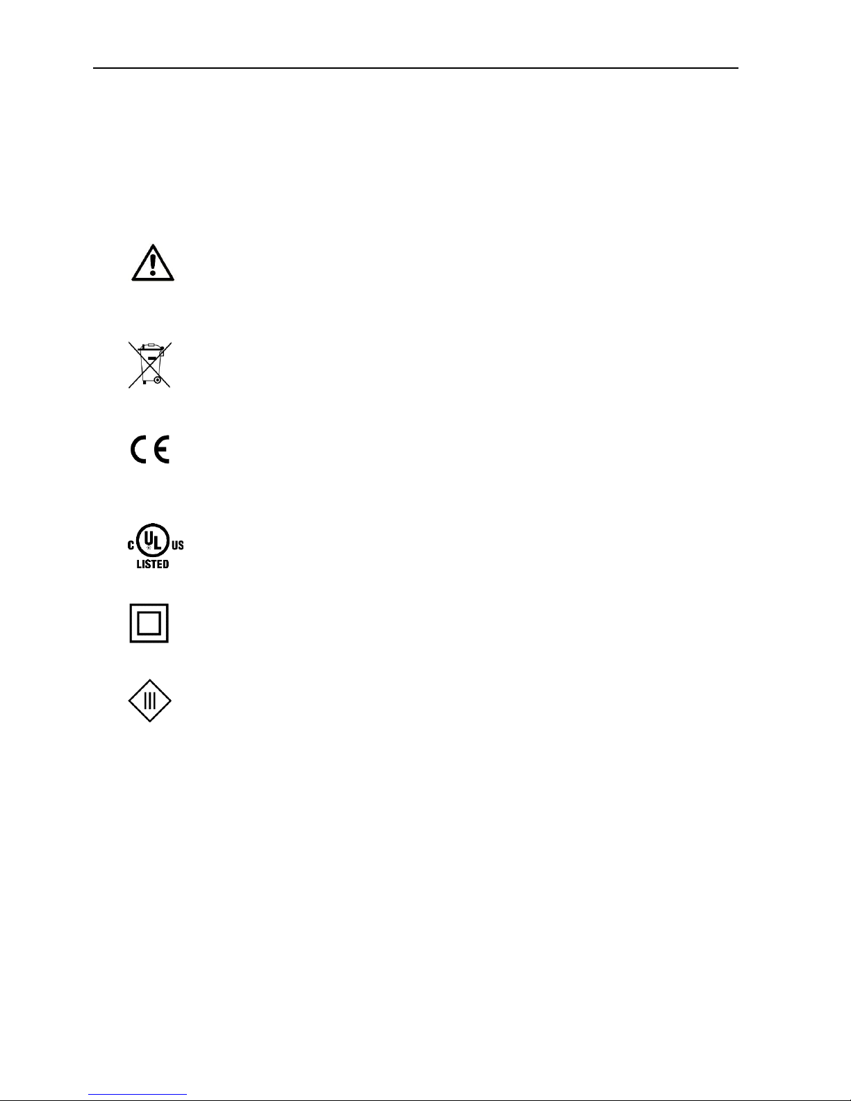
2.6 Markings on the Product
The identification plate of the product is either a print or a label on a face of the
product. Amongst other things, it can contain the following markings, which are
explained in detail here.
Observe manual
This symbol indicates that the manual of the product contains
essential safety instructions that must be followed implicitly.
Dispose waste electronic equipment environmentally
compatible
This symbol indicates that waste electronic equipment must be
disposed separately from residual waste via appropriate collecting
points. See also Section Disposal in this manual.
CE marking
By applying a CE marking, the manufacturer confirms that the
product complies with the European directives that apply productspecific.
UL marking
By applying a UL marking, the manufacturer confirms that the
product complies with the obligatory safety requirements.
Appliance Class II - double insulated
This symbol indicates that the product complies with Appliance
Class II
Appliance Class III - protection by extra low voltage
This symbol indicates that the product complies with Appliance
Class III
2.7 Environmental Protection
Dispose the product and the packaging according to the relevant environmental
protection regulations. The Waste Disposal section in this manual contains notes
about disposing the product. Separate the packaging components of cardboard
and paper as well as plastic and deliver them to the respective collection systems
for recycling.
Page 12
Safety
ETSM / ETSU
12
2.8 Safety Instructions for Electrical Installation
The electrical connection must only be made by authorised expert personnel according to the wiring diagrams.
The notes to the electrical connection in the manual must be observed. Otherwise,
the protection category might be affected.
The safe disconnection of circuits, which are hazardous when touched, is only ensured if the connected devices meet the requirements of VDE T.101 (Basic requirements for safe disconnection).
The supply lines are to be routed apart from circuits, which are hazardous when
touched, or isolated additionally for a safe disconnection.
An easily accessible isolation device that disconnects all lines must be installed
prior to commissioning of the device to be able to isolate it completely from power
supply.
2.9 General Safety Instructions
Caution!
Electrostatic discharges may damage the product!
Damage of the product.
Observe the general safety precautions when handling
electrostatic-discharge-sensitive parts.
Caution!
Incomplete voltage isolation!
Damage of the product.
To isolate the voltage from the device, disconnect any
supply circuit with its respective isolation device if a
redundant power supply is used.
Caution!
Moisture and liquids from the environment may seep into
the interior of the product!
Fi re hazard and damage of the product.
The product must not be used in wet or damp
environments, or in the direct vicinity of water. Install the
product at a dry location, protected from water spray.
Disconnect the power supply before you perform any work
on a device which may have been in contact with
moisture.
Page 13
ETSM / ETSU
Safety
13
Caution!
Short circuits and damage due to improper repairs and
modifications as well as opening of maintenance areas!
Fi re hazard and damage of the product.
It is not permitted to open the product for repair or
modification.
Caution!
Overvoltage and voltage peaks from the mains supply!
Fi re hazard and damage of the product due to overvoltage .
Install suitable overvoltage protection.
Caution!
Damage due to chemicals!
Ketones and chlorinated hydrocarbons dissolve the plastic
housing and damage the surface of the device.
Never let the device come into contact with ketones (e.g.
acetone) or chlorinated hydrocarbons, such as
dichloromethane.
Page 14

Using Open Source Software
ETSM / ETSU
14
3 Using Open Source Software
3.1 General Information
Our product ETSM / ETSU contains, amongst others, so-called open-source software that is provided by third parties and has been published for free public use.
The open-source software is subject to special open-source software licenses and
the copyright of third parties. Basically, each customer can use the open-source
software freely in compliance with the licensing terms of the respective producers.
The rights of the customer to use the open-source software beyond the purpose of
our product are regulated in detail by the respective concerned open-source software licenses. The customer use the open-source software freely, as provided in
the respective effective license, beyond the purpose that the open-source software
gets in our product. In case there is a contradiction between the licensing terms for
our product and the respective open-source software license, the respective relevant open-source software license takes priority over our licensing terms, as far as
the respective open-source software is concerned by this.
The use of the used open-source software is possible free of charge. We do not demand usage fees or any comparable fees for the use of the open-source software
contained in our product. The use of the open-source software in our product by
the customer is not part of the earnings we achieve with the contractual compensation.
All open-source software programs contained in our product can be taken from the
available list. The most important open-source software licenses are listed in the Licenses section at the end of this publication.
As far as programs contained in our product are subject to the GNU General Public
License (GPL), GNU Lesser General Public License (LGPL), Clarified Artistic License
or another open-source software license, which regulates that the source code
must be made available, and if this software is not already delivered in source code
on a data carrier with our product, we will send you this at any time upon request.
If it is required to send this on a data carrier, the sending will be made against payment of a cost compensation of € 10,00. Our offer to send the source code upon
request ceases automatically 3 years after delivery of our product to the customer.
Requests must be directed to the following address, if possible under specification
of the serial number:
INSYS MICROELECTRONICS GmbH
Hermann-Köhl-Str. 22
93049 Regensburg, Germany
Phone +49 941 58692 0
Fax +49 941 58692 45
E-mail: support@insys-icom.de
Page 15

ETSM / ETSU
Using Open Source Software
15
3.2 Special Liability Regulations
We do not assume any warranty or liability, if the open-source software programs
contained in our product are used by the customer in a manner that does not comply any more with the purpose of the contract, which is the basis of the acquisition
of our product. This concerns in particular any use of the open-source software
programs outside of our product. The warranty and liability regulations that are provided by the respective effective open-source software license for the respective
open-source software as listed in the following are effective for the use of the
open-source software beyond the purpose of the contract. In particular, we are not
liable, if the open-source software in our product or the complete software configuration in our product is changed. The warranty granted with the contract, which is
the basis of the acquisition of our product, is only effective for the unchanged
open-source software and the unchanged software configuration in our product.
3.3 Used Open-Source Software
The following open-source software is being used in the product:
Software/project
Version
Li censes
FreeRTOS
7.0.0
GPL2 + MODIFIED BY the FreeRTOS
exception
ASF
3.21.0/3.18.1
Atmel ASF license
IwIP
1.4
BSD
exTLS
1.5.2
BSD
Page 16

Version History
ETSM / ETSU
16
4 Version History
Version
Modification
1.0
Release
Page 17

ETSM / ETSU
Device Variants
17
5 Device Variants
This manual describes two different variants of the INSYS icom switch. These are:
• Unmanaged Switch ETSU-E100
• Lite-managed Switch ETSM-E100
If the devices are different, this will be mentioned explicitly in the respective
sections.
Page 18

Scope of Delivery
ETSM / ETSU
18
6 Scope of Delivery
The scope of delivery includes all accessories listed below. Please check if all
accessories are included in the box. If a part is missing or damaged, please contact
your distributor.
• Switch
• Quick Installation Guide
• Safety Instructions
The scope of delivery does not include optional accessories. The following parts are
available from your distributor or INSYS icom:
• Din rail power supply units
Page 19

ETSM / ETSU
Technical Information
19
7 Technical Information
7.1 Technical Data
7.1.1 Physical Features
All specified data was measured with nominal input voltage, at full load, and an
ambient temperature of 25 ℃. The limit value tolerances are subject to the usual
variations.
Physical Feature
Value
Operating voltage
9.6 V … 60 V DC
18 V … 30 V AC
Power consumption (V = 9.6 … 24 V)
(V = 60 V)
typ. 2.4 W / max. 2.65 W
typ. 3.9 W / max. 4.2 W
Level digital input
HIGH level = 11 ... 30 V
LOW level = 0 ... 5 V
Contact open condition: LOW
Current consumption input at HIGH
potential
Max. 4 mA at 24 V, 10 mA at 30 V
Fault contact (NO), max. switch voltage
60 V (DC) / 30 V (AC)
Fault contact (NO), max. current load
1 A at 60 V DC / 30 V AC
Weight
300 g
Dimensions (Width x Depth x Height)
65 mm x 49 mm x 105 mm
(depth with connector)
Temperature range
-40 °C … 70 °C (operation)
-40 °C … 85 °C (storage)
Maximum permissible humidity
10 … 95% non-condensing
IP rating
Housing IP20, connectors IP40
Ta b le 1: ETSM/ETSU – physical features
Page 20

Technical Information
ETSM / ETSU
20
7.1.2 Technological Features
Te chnological Feature
Description
6-port Ethernet switch
10/100 Mbit/s full/half duplex auto sense;
automatic detection of "crossover" or "patch"
wiring.
USB interface
USB 2.0 host; socket type A, max. 500 mA
Ta b le 2: ETSM/ETSU – technological features
7.2 Connections and display elements
Fig u re 1: ETSM / ETSU – connections and display elements
Page 21

ETSM / ETSU
Technical Information
21
Item
Designation
Description
1
V1
Power supply, redundant positive terminal 1
2
GND
Ground
3
Fault
Fault contact, potential-free (ETSM only)
4
DI+
Digital input, positive connection (ETSM only)
5
DI-
Digital input, negative connection (ETSM only)
6
Fault
Fault contact, potential-free (ETSM only)
7
GND
Ground
8
V2
Power supply, redundant positive terminal 2
Ta b le 3: ETSM / ETSU – push-in termina l connector connections
Fig u re 2: ETSM / ETSU – USB socket (ETSM only)
Item
Designation
Description
1
VBUS
+5 V
2
D-
Data -
3
D+
Data +
4
GND
Ground
Ta b le 4: ETSM / ETSU – USB socket connections (ETSM only)
Page 22
Technical Information
ETSM / ETSU
22
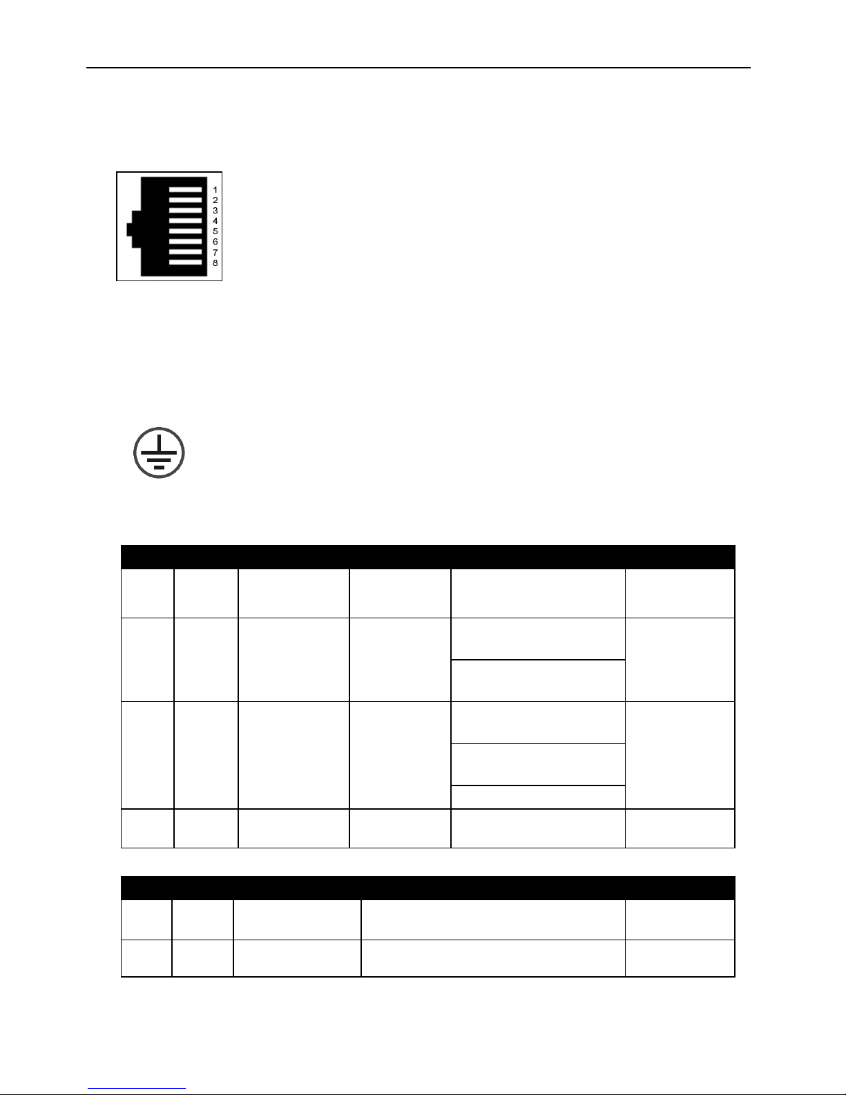
1
TX+
Data TX+
2
TX-
Data TX-
3
RX+
Data RX+
4
n/c
not connected
5
n/c
not connected
6
RX-
Data RX-
7
n/c
not connected
8
n/c
not connected
Fig u re 3: ETSM / ETSU – Ethernet port connections
Grounding connection
Fig u re 4: ETSM / ETSU – grounding connection
The variants ETSM and ETSU have different display elements.
LE D
Colour
Function
off
blinking
on
PWR
green
Supply
not
sufficient
Error
sufficient
MOD
green
Operating
mode
not ready
for
operation
USB interface in
device mode (1 Hz)
ready for
operation
Firmware update
(10 Hz)
ERR
red
Error
no error is
present
configuration file
invalid (1 Hz)
system error
or over temperature
fault contact active
(10 Hz)
supply failure (30 Hz)
DI
green
Digital input
inactive
active
Ta b le 5: ETSM – mea ning of t he display elements
LE D
Colour
Function
off
on
V1
green
Supply V1
not connected / sufficient
sufficient
V2
green
Supply V2
not connected / sufficient
sufficient
Ta b le 6: ETSU – meaning of the display elements
Page 23

ETSM / ETSU
Technical Information
23
Each switch port has a green and a yellow LED.
LE D
Colour
Function
off
blinking
on
LA
green
Link / Activity
not connected
Data traffic
connected
SP
yellow
Data rate
10 Mbit/s
100 Mbit/s
Ta b le 7: ETSM / ETSU – meaning of the display elements at the Ethernet port
7.2.1 Connecting the connectors
The wires are contacted maintenance-free in the connector via screw terminal.
The permissible wire cross-sections can be found in the following tables.
Wire
Cross-section
Nominal cross-section
2.5 mm²
Rigid
0.2 – 2.5 mm²
Flexible
0.2 – 2.5 mm²
Flexible with end sleeve
0.25 – 2.5 mm²
Ta b le 8: Permissible wire cross-sections for connectors
Page 24
Assembly
ETSM / ETSU
24
8 Assembly
This section describes how to mount the switch to a DIN rail, connect the
power supply and uninstall it again. Observe the instructions in the "Safety"
section of this manual, in particular the "Safety Instructions for Electrical
Installation" for that purpose unconditionally.
Caution!
Moisture and liquids from the environment may seep into
the interior of the device!
Fi re hazard and damage of the product.
The device must not be used in wet or damp
environments, or in the direct vicinity of water. Install the
device at a dry location, protected from water spray.
Disconnect the power supply before you perform any work
on a device which may have been in contact with
moisture.
Caution!
The device could be destroyed if the wrong power supply
is used!
If the device is operated with a power supply that supplies
a voltage exceeding the permissible operating voltage, it
will be destroyed.
Make sure that you use the suitable power supply. Refer to
the Technical Data section for the proper voltage range.
Mounting the device to the DIN rail
How to mount the switch to a DIN rail:
1. Place the device at the DIN rail Hook the upper DIN rail groove into
place behind the upper edge of the DIN rail.
2. Fold down the device perpendicular to the DIN rail until the lower
DIN rail groove latches in the DIN rail.
3. Connect the grounding cable to the grounding connection of the
device.
The switch is now readily mounted.
Page 25

ETSM / ETSU
Assembly
25
Connecting the power supply
The device has already been mounted to the DIN rail.
The power supply is connected and switched off.
1. Remove the push-in terminal connector from the switch.
2. Connect the ground lead of the power supply to the terminal "GND"
of the terminal connector.
3. Connect the positive lead of the power supply to the terminal "V1" of
the terminal connector.
4. Fasten the push-in terminal connector at the switch again.
The switch is now connected to the power supply.
Disconnecting the power supply
The device is mounted to the DIN rail.
The power supply is connected and switched off.
1. Remove the push-in terminal connector from the switch.
The switch is disconnected from the power supply.
Removing the device from the DIN rail
How to uninstall the switch from a DIN rail in a switch cabinet:
The power supply of the switch cabinet is switched off and secured against
being switched on accidentally.
The push-in terminal connector, the grounding connection and all Ethernet
cables at the device are disconnected.
1. Push the device slightly down to compress the retaining spring and
swing it away from the DIN rail.
2. Un-hook the device and take it off perpendicularly to the DIN rail.
The switch is now detached.
Page 26

Commissioning, Operation and Configuration ETSU
ETSM / ETSU
26
9 Commissioning, Operation and Configuration
ETSU
The unmanaged Switch ETSU does not require any configuration and is ready for
operation directly upon switching it on.
Page 27

ETSM / ETSU
Commissioning, Operation and Configuration
ETSM
27
10 Commissioning, Operation and Configuration
ETSM
10.1 Commissioning
The lite-managed switch ETSM is delivered pre-configured. The factory configuration is set such that after powering the switch, the device transmits data to all
Ethernet ports immediately. The following settings are set as default:
• Web interface IP address: 192.168.0.2
• Web interface user name: admin
• Web interface password: password
• Web interface access: via any Ethernet
port
• Ethernet ports: activated
• Auto-Negotiation: activated
• VLAN, QoS, port mirroring: deactivated
• Link aggregation: deactivated
• Fault contact: Normally Open
• Fault contact events: V1 or V2 fault; over
temperature
• TRAP protocol: UDP
• TRAP IP address: 192.168.0.1:4321
• TRAP events: V1 or V2 fault; over
temperature, internal fault
• Logging function: activated
Proceed as follows for commissioning:
1. Connect the power supply
2. Connect the PC / notebook to one of the Ethernet ports of the device
3. The connected PC / notebook must have the following network settings:
• Fix IP address: 192.168.0.1
• Subnet mask: 255.255.255.0
4. Start a web browser and enter the IP address of the device
5. Perform the desired configuration of the device
6. Connect the switch with your network devices
Page 28
Commissioning, Operation and Configuration
ETSM
ETSM / ETSU
28
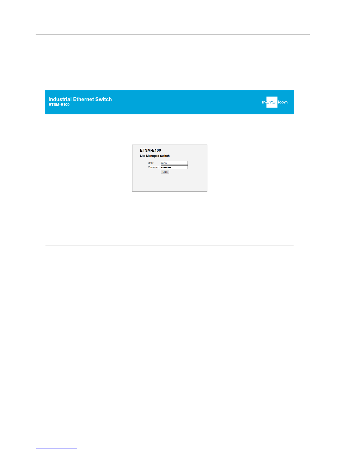
10.2 Operation via the web interface
The configuration via the web interface allows you to change the device settings
via the network. The IP address of the switch must be entered in the web browser
to get access. The default IP address is 192.168.0.2.
To get access to the system, the user must authenticate himself. This takes place
using a user name and a password. Subsequently, the web interface will be loaded
The pre-configured access data are:
• User: admin
• Password: password
If broadcast packets are sent permanently through the switch in the
network, it may happen that the web interface cannot be accessed.
Page 29
ETSM / ETSU
Commissioning, Operation and Configuration
ETSM
29
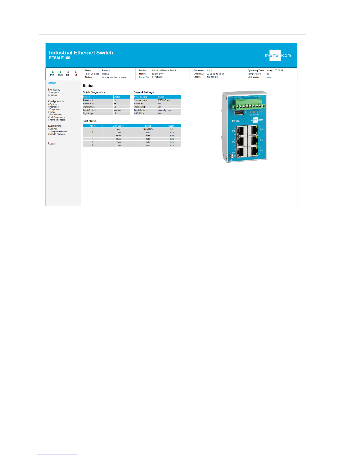
The left and upper part of the web interface will be displayed on all pages..
The left area is used for navigation and divided into the categories Monitoring, Configuration and Maintaining. Monitoring shows the states of various parts of the system. The Configuration are allows you to change settings and the Maintaining area
allows you to save configurations or upload firmware updates.
The current page is highlighted.
The status bar at the top of the web interface shows the most important information of the system and updates every 10 seconds. There you can find the LED
indications of the device, the power supply state, the fault contact state, information about the last error, the temperature and the system uptime.
After logging in, the dashboard appears which shows a detailed overview and provides initial information on the state of the network ports already. In addition, this
page contains a graph showing the connections of the device.
Page 30
Commissioning, Operation and Configuration
ETSM
ETSM / ETSU
30
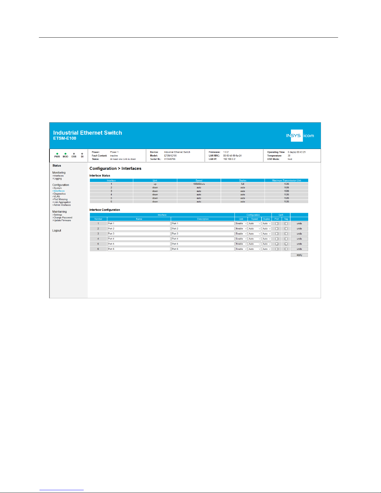
10.3 Supported Switch Configuration
10.3.1 Ethernet Ports
The setting of the Ethernet ports is carried out in the web interface under
Configu-
ration > Interfaces
. The page contains two tables. The top shows the state of the
interfaces. The table below can be used to change the settings.
Page 31

ETSM / ETSU
Commissioning, Operation and Configuration
ETSM
31
The following settings are available for each port:
Op tion
Value
Description
Name
Name of the interface (max. 64 characters, no semicolon or line wrap)
Description
Description of the interface (max. 64 characters, no
semicolon or line wrap)
Link
Enable
Port activated
Disable
Port deactivated
Speed
100 MBit
Port set to 100 MBit
10 MBit
Port set to 10 MBit
Auto
Port uses auto-negotiation to negotiate the speed
Duplex
Full
Port uses full duplex
Half
Port uses half duplex
Auto
Port uses auto-negotiation to negotiate the duplex
setting
QoS
Port
All incoming packets arriving at an accordingly
configured port are prioritized.
Tag
Only packets with TOS (type of service) or PCP (priority code point) field higher than 3 are prioritized.
Ta b le 9: ETSM – port settings
Ports can be activated or deactivated using "Link Status". Deactivating
unneeded ports is recommended if a link-down event shall be monitored.
Auto-negotiation will negotiate the highest possible speed that is also supported by
the connected destination device. In case that auto-negotiation is not used, the
configuration for speed and duplex must be made for both network participants to
enable communication.
If the speed or duplex mode is set to "auto", this means that both
values are set to "auto".
Changes can be transmitted to the switch by clicking the "Apply" button. The
"undo" button can be used to read back the current configuration.
Deactivating administration ports is not possible due to security reasons.
Therefore, these must be deactivated as administration ports first.
QoS (Quality of Service allows to prioritize network traffic. The switch supports two
different procedures.
Port-based QoS can be activated on maximum 4 ports. Frame-based
QoS has no such limitations.
Page 32

Commissioning, Operation and Configuration
ETSM
ETSM / ETSU
32
10.3.2 Port Mirroring
Port mirroring (or port monitoring) allows to duplicate network traffic to an observation port and analyse it there. The incoming and outgoing traffic can be duplicated independently per port.
The settings for port mirroring are made in the web interface under
Configuration >
Port Mirroring
.
Port mirroring can be activated or deactivated in the left table (default: deactivated).
The observation port (destination port) is also configured here.
The table on the right defines the ports from which incoming and/or outgoing traffic will be mirrored to the destination port.
The settings are transmitted using the "set" button.
Page 33

ETSM / ETSU
Commissioning, Operation and Configuration
ETSM
33
10.3.3 Link Aggregation
Link aggregation (also known as port trunking) allows to bundle several ports to enable a higher redundancy or data throughput between two devices.
The link aggregation settings are made in the web interface under
Configuration >
Link Aggregation
.
Each interface can be assigned to Group A, Group B or no group (none).
The settings are transmitted to the device using the "submit" button.
A maximum of 2 groups are supported. The connected device must
also be configured for link aggregation.
Page 34

Commissioning, Operation and Configuration
ETSM
ETSM / ETSU
34
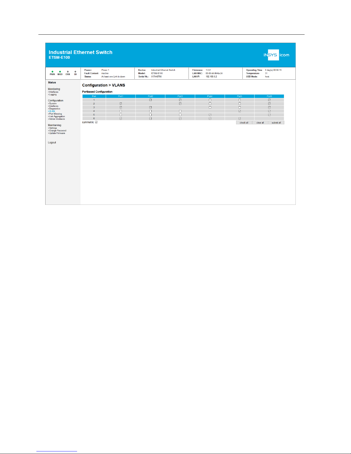
10.3.4 VLAN
VLANs allow to segment a network and operate this like several small networks.
VLANs can be configured in the web interface under
Configuration > VLAN
.
The configuration options are very flexible; connections between all ports and in
each direction can be permitted or prohibited.
This is specified in the table as follows: Packets that arrive at one of the ports at the
left are only forwarded to ports which are checked in this line.
In most cases, the switching options for incoming and outgoing traffic are symmetrical. To activate symmetric features, check "symmetric" below the table.
To apply all settings, click on "submit all".
In order to accelerate the setting effort, "check all" or "clear all" can be
used to select all or no interfaces. The transfer of the settings to the
switch must always be made in addition.
The following image shows the configuration of two VLAN networks consisting of
ports 1, 2, 3 or 4, 5. Port 6 exists in both networks.
Therefore, ports 1, 2, 3 cannot communicate with the ports 4, 5. Port 6 can communicate with each of the other ports.
Page 35
ETSM / ETSU
Commissioning, Operation and Configuration
ETSM
35
If different VLANs are connected with cables, problems with data
transfer may occur. It is recommended to combine the respective
VLANs.
Page 36

Commissioning, Operation and Configuration
ETSM
ETSM / ETSU
36
10.4 Device Diagnosis
10.4.1 LED display
A quick diagnosis of the device is possible using the LED display.
The LED display and the respective failure conditions are described in the connec-
tions and display elements section.
10.4.2 Failure conditions
The system detects faults and errant events and signals it to the user. The following
states are detected:
Fa ult code
Designation
Description
0 - No fault
2
Power
Selected power supply is under the necessary voltage (refer to Power supply under System Access Settings)
4
Temperature
The configured alarm value of the temperature has
been exceeded
8
Link down
Activatd network port has no data connection
64
Config
Loaded configuration file is invalid
32, 64, 128
Internal
Internal device fault
256
DI1
Digital input has triggered
Ta b le 10: E TSM – Failure conditions and code s
The upper status bar of the web interface shows the actual status as text. The status codes are sent as trap messages. If several faults occur simultaneously, the
sum is displayed.
Example: A status code of 10 means power (2) and link down (8).
In case a failure condition occurs, messages can be output via fault contact and
traps.
Page 37
ETSM / ETSU
Commissioning, Operation and Configuration
ETSM
37
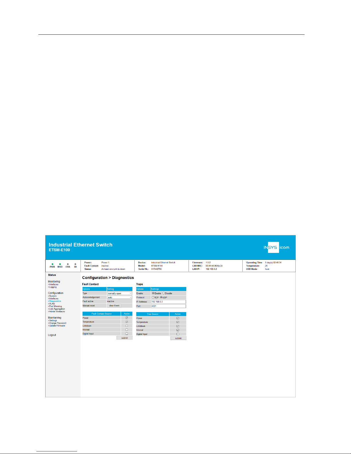
10.4.3 Fault contact
The fault contact is used to signal occurring failure conditions. Devices that process
this message can be connected to the fault contact.
The configuration of the Fault Contact is performed in the web interface under
Con-
figuration > Fault Contact
. Different events can be configured as trigger for the
fault contact:
• Power (active as default)
• Temperature (active as default)
• Link down
• Internal
• Digital input
Moreover, the reset behaviour of the fault contact can be configured:
• "automatic": The fault contact will be reset automatically (inactive) if the
problem that caused the trigger does not exist any more.
• "manual": The fault contact will be reset automatically (inactive), as soon as
the button "reset" is clicked in the web interface. If there are one or more
active trigger events, the fault contact remains active.
The electrical properties and the connection of the fault contact are described in
Technical Data.
Page 38

Commissioning, Operation and Configuration
ETSM
ETSM / ETSU
38
10.4.4 Traps
Traps are used to signal failure conditions of the device. Traps are data packets that
are sent to a configured network address via the network. This allows a monitoring
at the destination address.
The content of the data packet consists of two bytes which contains the current
failure condition code (refer to failure conditions).
Please note that these are no SNMP traps, but specific failure codes.
The following settings can be made in the web interface under
Configuration >
System
:
• Activate / deactivate traps (default: activated)
• Protocol: TCP, UDP (default: UDP)
• Destination IP address (default: 192.168.0.1)
• Destination port: (default: 4321)
One or more of the following failure conditions can be configured as trigger of the
traps:
• Power (active as default)
• Temperature (active as default)
• Link down (active as default)
• Internal (active as default)
• Digital input
Page 39

ETSM / ETSU
Commissioning, Operation and Configuration
ETSM
39
10.4.5 Diagnosis services
The diagnosis services allows to perform an automated diagnosis via network.
SNMP and Modbus TCP are available for this. The services are configured under
Diagnosis in
Configuration > Diagnostics.
All services do not support authentication. Therefore, it is
recommended to use them only if required.
10.4.5.1 SNMP
The SNMP service allows to read device information via network.
The device supports SNMPv1 get and getnext requests. The change of settings us-
ing set messages is not supported.
The requests must be sent to the IP address of the device and the standard SNMP
port 161.
The read community is public.
The following MIB-II groups are available and can be requested using get and get-
next:
• System Group (1.3.6.1.2.1.1)
• Interfaces Group (1.3.6.1.2.1.2)
• Address Translation Group (1.3.6.1.2.1.3)
• IP Group (1.3.6.1.2.1.4)
• ICMP Group (1.3.6.1.2.1.5)
• TCP Group (1.3.6.1.2.1.6)
• UDP Group (1.3.6.1.2.1.7)
• SNMP Group (1.3.6.1.2.1.11)
The System Group outputs all data that is configured in the web interface under
Configuration > System
.
Page 40

Commissioning, Operation and Configuration
ETSM
ETSM / ETSU
40
10.4.5.2 Modbus TCP
Modbus TCP allows to read the status of the network and the device.
The Modbus TCP server is accessible on Modbus TCP standard port 502.
The Modbus TCP server can only serve one client at once.
Only read commands to input registers (function code 4) are supported. The read
command consists of 16 bit words. The following memory map shows the available data of the switch. The address consists of the start address 30001 (decimal)
and an offset. When reading out using an INSYS Device App (icom Data Suite or
Monitoring App) the addresses in the
INSYS-Adr. (dec)
column must be used as
register address for an input register. Names and description are ASCII-coded and
one word contains two characters. Not used characters are filled with 0x00.
The offsets are displayed as hexadecimal figures in the following table.
Offset
(he x)
Le ngth
(dec)
Description
Mea ning
INSYSAd r.
(dec)
0x0000
1 word
Vendor ID
(0xFFFF)
29999
0x0001
1 word
Unit ID (0x01)
30000
0x0002
1 word
Product Code
(0x003)
30002
0x0010
20 word
Vendor Name
30015
0x0030
20 word
Product Name
30047
0x0051
2 word
Firmware Version
30080
0x0053
2 word
Firmware Release Date
WORD 1: DD-HH
WORD 2: YY-MM
30082
0x0055
3 word
Ethernet Mac
Example Mac:
00:11:22:33:44:55:66
WORD 1: 11 22
WORD 2: 33 44
WORD 3: 55 66
30084
0x0058
1 word
Power 1
0x0000: Off
0x0001: On
30087
0x0059
1 word
Power 2
0x0000: Off
0x0001: On
30088
0x005A
1 word
Fault LED
0x0000: Off
0x0001: On
30089
Page 41

ETSM / ETSU
Commissioning, Operation and Configuration
ETSM
41
Offset
(he x)
Le ngth
(dec)
Description
Mea ning
INSYSAd r.
(dec)
0x005B-
0x007F
Invalid range
Can not be requested
3009030126
0x0080
1 word
DI 1
0x0000: Off
0x0001: On
0xFFFF: No Di
30127
0x0081
1 word
DI 2
0x0000: Off
0x0001: On
0xFFFF: No Di
30128
0x0082
1 word
DO 1
0x0000: Off
0x0001: On
0xFFFF: No Do
30129
0x0083
1 word
DO 2
0x0000: Off
0x0001: On
0xFFFF: No Do
30130
0x0084-
0x008F
Invalid range
Can not be requested
3013130142
0x0090
4 word
Product Serial
Number
30143
0x0095-
0x009F
Invalid range
Can not be requested
3014830158
0x1000
1 word /
port
Port Status
0x0000 => Link down
0x0001 => Link up
0x0002 => Disable
0xFFFF: No port
34095
0x1100
1 word /
port
Port Status
0x0000: 10M-Half
0x0001: 10M-Full
0x0002: 100M-Half
0x0003: 100M-Full
34351
0x1400
1 word /
port
Port description
Description (ASCII format)
35119
Ta b le 11: E TSM – Modbus offsets
It is possible to read multiple registers at once. However, it is to be observed that
no invalid ranges are contained since the request will then be answered with a failure.
Page 42

Commissioning, Operation and Configuration
ETSM
ETSM / ETSU
42
10.4.6 Digital input
The device has a digital input. Any other device can be connected to it as far as the
electrical specifications are complied with. The electrical properties and the connection of the fault contact are described in Technical Data.
A level change at the digital input is detected by the switch. It will be indicated by
the DI-LED and in the web interface.
In addition, a trap message can be sent. Moreover, the digital input can be configured as a trigger source of the fault contact.
It can be configured in the web interface under
Configuration > System
to which
level changes the digital input shall react:
• Rising edge
• Falling edge
• Disabled
If one edge is causing the event, the other edge will deactivate the event again.
Page 43

ETSM / ETSU
Commissioning, Operation and Configuration
ETSM
43
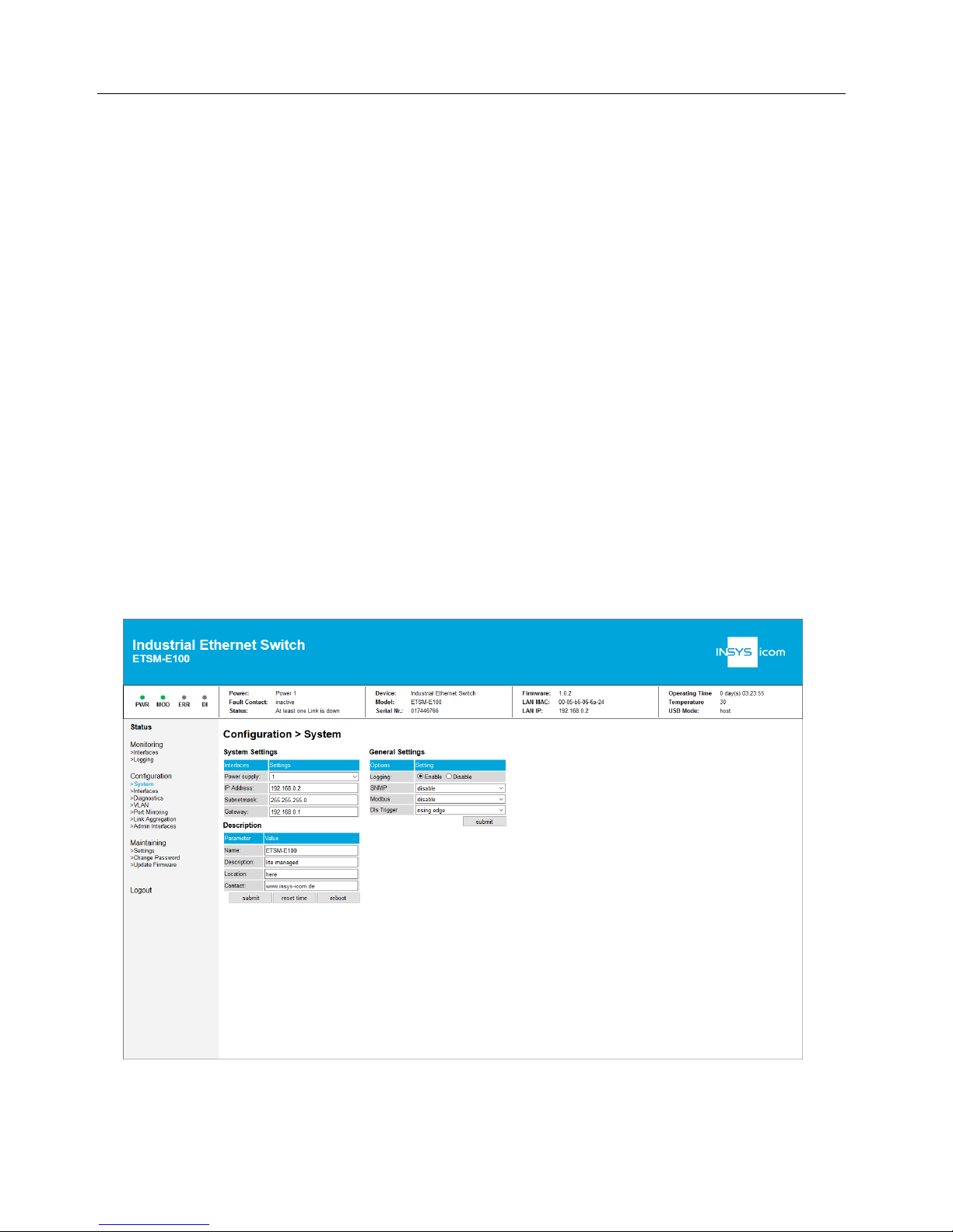
10.4.7 Log files
The device can record events and write them to log files. These contain system status, messages as well as events caused by the user.
The following log file settings can be made in the web interface under
Configura-
tion > System
in the
General Settings
section.
• enable / disable, default: enable
The log entries are displayed in the web interface under
Monitoring > Logging
. The
following table is an example of the log entries.
Ti me
Typ e
Description
0 day(s) 00:00:00
device
power on
0 day(s) 00:00:00
fault contact
inactive
0 day(s) 00:00:00
device
booted
0 day(s) 00:00:01
interface
interface 6 link up
0 day(s) 00:00:10
user
web interface login
0 day(s) 00:00:30
user
configuration file loaded
0 day(s) 00:00:30
fault contact
inactive
Ta b le 12: E TSM – log entries
The log file can also be downloaded from the device. To download the current log,
the
Download Current Log
button is available in the web interface under
Monitor-
ing > Logging
.
If a log file reaches a size of 1 MB, logging will continue in a new log
file with incremented number. The file with the highest number in its
name has the newest log entries therefore.
The internal memory has capacity for two such files. If they are full,
the first will be deleted and number of the other will be decremented
and a a new file will be written.
All log files can be copied to an USB flash drive under
Maintaining > Settings
using
"Copy to USB", "Logging Files".
Page 44
Commissioning, Operation and Configuration
ETSM
ETSM / ETSU
44
10.5 System Access Settings
10.5.1 IP address
The configuration of the IP address is performed in the web interface under
Config-
uration > System.
The IP address, the subnet mask and the gateway can be configured there and transmitted to the device using the "submit" button. The default settings are:
• IP address: 192.168.0.2
• Subnet mask: 255.255.255.0
• Gateway: 192.168.0.1
Changes of these settings become active after a restart of the system first. The system can be restarted using the "reboot" button.
10.5.2 Power supply
The power supply settings are in the web interface under
Configuration > System
.
It is possible to configure whether power is supplied via input V1 (1), input V2 (2) or
redundant via both inputs (1+2). Default setting is 1. In case no sufficient voltage is
present at the configured input (or at one of the inputs in case of setting 1+2), a
fault will be triggered.
Page 45

ETSM / ETSU
Commissioning, Operation and Configuration
ETSM
45
10.5.3 Administration port
Access to the web interface of the device can be blocked on certain ports in order
to limit device access.
This can be configured in the web interface under
Configuration > Admin Inter-
faces.
Deactivated ports cannot be configured for administration. This shall
avoid that the user locks out himself.
It is recommended to deactivate all unused ports, because the
management functions cannnot be reached any more under high
network load.
10.5.4 Password change
The password can be changed via the web interface or using an USB flash drive.
10.5.4.1 Web interface
The password can be configured under
Maintaining > Change Password
. The new
password must be entered twice for this due to reasons of security. Then, the password can be changed using the "change password" button.
10.5.4.2 USB
Alternatively, the password can also be chamged via USB. An USB flash drive is
necessary for this. It has to be prepared as described in the following section.
In order to change the password, an authentication file is required. This file must
have the name "newpassword.pass", the content is the new user name and new
password. The format requirements are described in the next section.
The following conventions apply for the password:
• at least 5 characters
• max. 16 characters
• no special characters, no umlauts
After plugging in the USB flash drive, the password will be changed automatically
without restart. If a web interface session is still active, the session becomes invalid
and the user will be logged out automatically.
Page 46

Commissioning, Operation and Configuration
ETSM
ETSM / ETSU
46
10.5.5 Configuration files
The whole system configuration can be managed using configuration files.
This can be made in the web interface under
Maintaining > Settings.
The following
functions are supported:
• Saving the configuration:
o to an USB flash drive ("config.cfg")
o as download to a PC
• Loading and applying the configuration files:
o from an USB flash drive ("config.cfg")
o as upload from a PC
• Loading the factory default settings
Configuration files can also be loaded and applied automatically from a
plugged USB flash drive (refer to next section).
Page 47

ETSM / ETSU
Commissioning, Operation and Configuration
ETSM
47
10.6 Configuration via USB flash drive
10.6.1 Function
The used USB flash drive must only have one partition and be forma tted with FAT.
The versions FAT12, FAT16 and FAT32 are supported.
New data from an USB flash drive are only applied automatically if it is able to authenticate with a valid user name and password. Therefore, an authentication file
named "userpassword.pass" must be present on the USB flash drive.
An authentication file must be present on the USB flash drive for a
configuration using the USB flash drive.
The authentication file must be an ASCII-coded text file without formatting. The
first line must contain the user name and the second line the password.
The directory structure of the USB flash drive must look like that:
• userpassword.pass
• log
o logfile1.log
o logfile2.log
o …
• configuser
o config.cfg
o confignew.cfg
• newpassword.pass
• OSYS_TQPRODUCT_Rxx.bin
10.6.2 Performing the configuration
To change the configuration of the switch, a valid configuration file must be present in the folder "configuser" of the USB flash drive. The configuration file must be
named "confignew.cfg". After plugging in the USB flash drive into the switch, the
device will load the new configuration file automatically and apply it after successful authentication.
Page 48
Commissioning, Operation and Configuration
ETSM
ETSM / ETSU
48
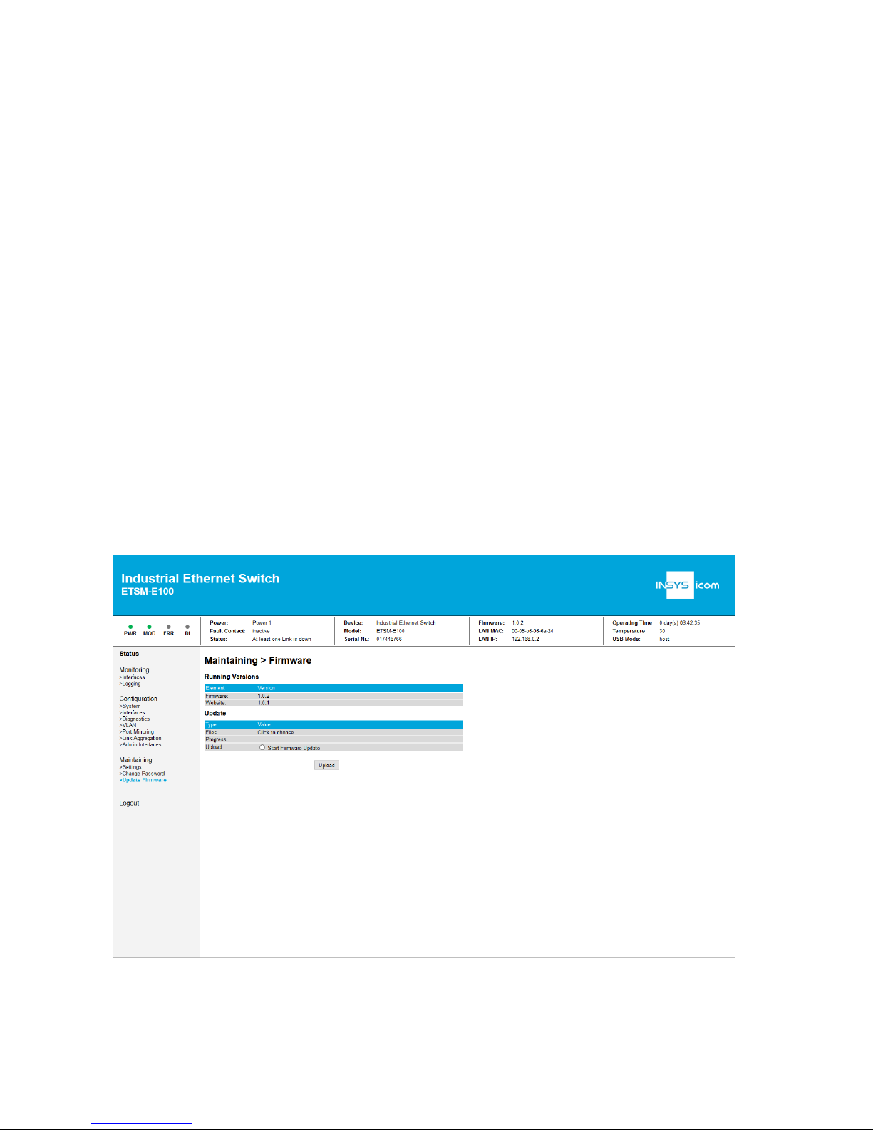
10.7 Firmware update
A firmware update can be made using the web interface. Optionally, a firmware update can be made using USB flash drive.
As long as a firmware update is running, the supply voltage must not
be interrupted.
This may take some time and can be seen on the System Status LEDs.
A firmware file which is compatible with the device is necessary for the firmware
update.
Never change the name of the firmware file.
10.7.1 Firmware update via web interface
The respective option is available under
Maintaining > Update Firmware
. The firm-
ware file can be selected in pop-up window after selecting
Start Firmware Update
.
Then, the firmware can be transmitted to the device using the "upload" button. It
will start automatically.
Page 49

ETSM / ETSU
Commissioning, Operation and Configuration
ETSM
49
10.7.2 Firmware update via USB flash drive
To install a firmware update via an USB flash drive, an USB flash drive that can be
authenticated must be used (refer to respective section). An authentication file has
to exist on the USB flash drive. The firmware file must also be in the root directory.
The firmware update will start automatically after the USB flash drive is connected
to the device. During this process, the MOD LED will flashes as described in the
connections and display elements section.
Page 50

Maintenance, Repair and Troubleshooting
ETSM / ETSU
50
11 Maintenance, Repair and Troubleshooting
11.1 Maintenance
The product is maintenance-free and does not require special regular maintenance.
11.2 Troubleshooting
If a failure occurs during the operation of the product, you will find troubleshooting
tips in the "Knowledge Base" on our web site (http://www.insysicom.de/knowledge/). If you need further support, please contact your reseller or
INSYS icom. You can contact our support team via e-mail under support@insystec.de.
11.3 Repair
Send defect devices with detailed failure description to the source of supply of your
device. If you have purchased the device directly from INSYS icom, send the device
to: INSYS MICROELECTRONICS GmbH, Hermann-Köhl-Str. 22, 93049 Regensburg.
Before dispatching the device:
• Backup the configuration on the device and any other stored data if required.
Caution!
Short circuits and damage due to improper repairs and
modifications as well as opening of products.
Fi re hazard and damage of the product.
It is not permitted to open the product for repair or
modification.
Page 51

ETSM / ETSU
Waste Disposal
51
12 Waste Disposal
12.1 Repurchasing of Legacy Systems
According to the new WEEE guidelines, the repurchasing and recycling of legacy
systems for our clients is regulated as follows:
Please send those legacy systems to the following address, carriage prepaid:
Frankenberg-Metalle
Gaertnersleite 8
D-96450 Coburg
Germany
This regulation applies to all devices which were delivered after August 13, 2005.
Please consider possible stored passwords or security certificates
before disposing the device. It is recommended to block possible
existing access rights for the device (e.g. on your VPN server) and
reset the device to default settings (if possible), before passing it on or
disposing it.
Page 52

Declaration of Conformity
ETSM / ETSU
52
13 Declaration of Conformity
Hereby, INSYS Microelectronics GmbH declares that herein described device types
are in compliance with Directives 2014/30/EU and 2011/65/EU. The full text of the
EC Declaration of Conformity is available under the following Internet address:
www.insys-icom.com/manual
Page 53

ETSM / ETSU
Tables and Diagrams
53
14 Tables and Diagrams
14.1 List of Tables
Table 1: ETSM/ETSU – physical features ............................................................ 19
Table 2: ETSM/ETSU – technological features..................................................... 20
Table 3: ETSM / ETSU – push-in terminal connector connections ........................ 21
Table 4: ETSM / ETSU – USB socket connections (ETSM only) ............................ 21
Table 5: ETSM – meaning of the display elements .............................................. 22
Table 6: ETSU – meaning of the display elements ............................................... 22
Table 7: ETSM / ETSU – meaning of the display elements at the Ethernet port ..... 23
Table 8: Permissible wire cross-sections for connectors ...................................... 23
Table 9: ETSM – port settings ............................................................................ 31
Table 10: ETSM – Failure conditions and codes .................................................. 36
Table 11: ETSM – Modbus offsets ..................................................................... 41
Table 12: ETSM – log entries ............................................................................. 43
14.2 List of Diagrams
Figure 1: ETSM / ETSU – connections and display elements ................................ 20
Figure 2: ETSM / ETSU – USB socket (ETSM only) .............................................. 21
Figure 3: ETSM / ETSU – Ethernet port connections ............................................ 22
Figure 4: ETSM / ETSU – grounding connection ................................................. 22
Page 54

Index
ETSM / ETSU
54
15 Index
Accessories................................... 18
Additional information ..................... 8
Alternative results............................ 8
Assembly ...................................... 24
Auto-negotiation ........................... 31
Breakdown...................................... 9
Checkmark...................................... 8
Commissioni ng ............................. 27
Configuration file ........................... 46
Defects liability terms ...................... 6
Diagnosis .................................36, 39
Digital input .................................. 42
DIN rail ....................................24, 25
Electrical installation ...................... 12
Environment ............................12, 24
Environmental Protection ............... 11
Ethernet port ................................. 30
Explosive atmosphere ...................... 9
Failure conditions .......................... 36
Fault contact ............................19, 37
Firmware update ........................... 48
Formatting ...................................... 8
General safety instructions ............. 12
Ground ......................................... 21
Housing ........................................ 13
Humidity ....................................... 19
Intended Use................................... 9
Interface ....................................... 13
IP rating ........................................ 19
Key word ........................................ 7
LED display ................................... 36
Link Aggregation ........................... 33
Liquids .....................................12, 24
Log files ........................................ 43
Marking .......................................... 7
Modbus TCP ................................. 40
Modification ............................ 13, 50
Moisture ................................. 12, 24
Open Source ................................. 14
Operating voltage .......................... 19
Overvoltage ................................... 13
Overvoltage protection ................... 13
Password ...................................... 45
Permissible limit ............................ 10
Personnel ...................................... 10
Port mirroring ................................ 32
Power consumption ....................... 19
Preface ........................................... 6
Prerequisites ................................... 8
Qualification .................................. 10
Quality of Service........................... 31
Recycling ...................................... 51
Removal........................................ 24
Repair ..................................... 13, 50
Repurchasing ................................ 51
Responsibilities of the operator....... 10
Safety ............................................. 9
Scope of Delivery........................... 18
Short-cut ................................. 13, 50
SNMP ........................................... 39
Storage ......................................... 10
Switch .......................................... 20
Switch cabinet............................... 25
Symbol ....................................... 7, 8
Transport ...................................... 10
Traps ............................................ 38
Usage ............................................. 9
USB ................................... 20, 45, 47
VLAN ............................................ 34
Water spray............................. 12, 24
Web interface .......................... 28, 44
Wiring........................................... 24
Page 55

 Loading...