

insys icom 56k, 4.2 User Manual

INSYS Modem 56k
AC/DC 4.2
Manual


Copyright © March 14 INSYS MICROELECTRONICS GmbH
Any duplication of this manual is prohibited. All rights on this documentation and
the devices are with INSYS MICROELECTRONICS GmbH Regensburg.
Trademarks
The use of a trademark not shown below is not an indication that it is freely availa-
ble for use.
MNP is a registered trademark of Microcom Inc.
IBM PC, AT, XT are registered trademarks of International Business Machine Corporation.
INSYS®, e-Mobility LSG® and e-Mobility PLC® are registered trademarks of INSYS
MICROELECTRONICS GmbH.
Windows™ is a registered trademark of Microsoft Corporation.
Linux is a registered trademark of Linus Torvalds.
Publisher:
INSYS MICROELECTRONICS GmbH
Hermann-Köhl-Str. 22
D-93049 Regensburg, Germany
Phone: +49 941 58692 0
Fax: +49 941 58692 45
E-mail: info@insys-icom.com
Internet: http://www.insys-icom.com
Date: Mar-14
Item: 31-22-03.120
Version: 2.3
Language: EN

Content
1 Preface ..................................................................................................... 7
1.1 Defects Liability Terms .......................................................................................... 7
1.2 Marking of Warnings and Notes ............................................................................ 8
1.2.1 Symbols and Key Words .......................................................................... 8
1.3 Symbols and the Formatting in this Manual .......................................................... 9
2 Safety ..................................................................................................... 10
2.1 Usage According to the Regulations ................................................................... 10
2.2 Permissible Technical Limits ................................................................................ 11
2.3 Responsibilities of the Operator ........................................................................... 11
2.4 Qualification of the Personnel .............................................................................. 11
2.5 Instructions for Transport and Storage ................................................................ 11
2.6 Markings on the Product ..................................................................................... 12
2.7 Environmental Protection .................................................................................... 12
2.8 Safety Instructions for Electrical Installation ........................................................ 13
2.9 General Safety Instructions .................................................................................. 13
3 Scope of Delivery ................................................................................... 15
4 Technical Data ....................................................................................... 16
4.1 Physical Features ................................................................................................. 16
4.2 Technological Features ........................................................................................ 17
4.3 Certifications ........................................................................................................ 17
5 Display and Control Elements ................................................................ 18
5.1 Meaning of the Displays ...................................................................................... 19
5.2 Function of the Control Elements ........................................................................ 19
6 Connections ........................................................................................... 20
6.1 Front Panel Connections ...................................................................................... 20
6.2 Terminal Connections on the Top ........................................................................ 21
6.3 Terminal Connections on the Bottom .................................................................. 22
6.4 Pin Assignment of the Serial Interface ................................................................. 23
6.5 RJ45 Phone Connection ...................................................................................... 24
7 Function Overview ................................................................................. 25
8 Mounting ............................................................................................... 28
9 Initial Operation ...................................................................................... 32
4 Mar-14

Contents
10 Operating Principle ................................................................................ 34
10.1 Operation with the Terminal Program .................................................................. 34
10.2 Operation with HSComm Modem ....................................................................... 35
10.3 User Interface of the Software HSComm Modem ............................................... 36
11 Functions ............................................................................................... 39
11.1 Establishing or Accepting a Data Connection ...................................................... 39
11.2 Select Country-Specific Presets ........................................................................... 41
11.3 Automatic Baud Rate Detection .......................................................................... 42
11.3.1 Serial Connection ................................................................................... 42
11.3.2 Phone Connection .................................................................................. 43
11.4 Data Buffer for Serial Data Transmission ............................................................. 43
11.5 Bit Direct Mode ................................................................................................... 44
11.6 Data Flow Control (Handshake) ........................................................................... 45
11.6.1 Hardware data flow control (RTS/CTS) .................................................. 45
11.6.2 Software data flow control (XON/XOFF) ................................................ 46
11.7 Error correction .................................................................................................... 47
11.8 Data Compression ............................................................................................... 48
11.9 Selective Call Acceptance .................................................................................... 49
11.10 Switching Outputs ............................................................................................... 50
11.11 Alarm Inputs ........................................................................................................ 51
11.12 Sending messages via Data connection, SMS or Fax .......................................... 52
11.13 Manual Sending of Messages.............................................................................. 55
11.14 Switching on the Remote Configuration .............................................................. 56
11.15 Remote Configuration of the INSYS Modem 56k AC/DC 4.2 ............................... 57
11.16 Switching / Querying of the Outputs / Activate Inputs via DTMF ........................ 58
11.17 Switching of the Outputs / Queries of the Inputs via DTMF ................................ 59
11.18 Access Control and Security Callback ................................................................. 61
11.19 Idle Connection Control with Data Transmit Control ........................................... 64
11.20 Priority Circuit for a Phone Connected in Series .................................................. 65
11.21 Operation with a PLC ........................................................................................... 67
11.22 Resetting the Device ............................................................................................ 68
11.23 Firmware Update ................................................................................................. 69
12 Waste Disposal ...................................................................................... 71
12.1 Repurchasing of Legacy Systems ........................................................................ 71
13 Declaration of Conformity ...................................................................... 72
14 AT Command Reference ........................................................................ 73
14.1 AT Messages ..................................................................................................... 101
15 Country Codes ..................................................................................... 104
Mar-14 5

Content
16 S Registry ............................................................................................ 108
16.1 Overview S Registry .......................................................................................... 108
16.2 Description S Registry ....................................................................................... 110
17 SMS Provider / Service Center ............................................................. 119
17.1 Alarm via SMS ................................................................................................... 119
17.2 Alarm Using E-Mail via SMS .............................................................................. 119
18 Tables and Diagrams............................................................................ 120
18.1 List of Tables ..................................................................................................... 120
18.2 List of Diagrams ................................................................................................ 120
19 Index .................................................................................................... 121
6 Mar-14

INSYS Modem 56k AC/DC 4.2
Preface
7
1 Preface
This manual allows for the safe and efficient use of the product. The manual is part
of the product and must always be stored accessible for installation, commissioning and operating personnel.
1.1 Defects Liability Terms
A usage not according to the intended purpose, an ignorance of this documentation, the use of insufficiently qualified personnel as well as unauthorised modifications exclude the liability of the manufacturer for damages resulting from this. The
liability of the manufacturer ceases to exist.
The regulations of our Delivery and Purchasing Conditions are effective. These can
be found on our website (www.insys-icom.de/imprint/) under “General Terms and
Conditions“.
Preface
INSYS Modem 56k AC/DC 4.2
8
Danger!
Risk of severe or fatal injury
One of these symbols in conjunction with the key word
Danger indicates an imminent danger. It will cause death or
severe injuries if not avoided.
Warning!
Personal injury
This symbol in conjunction with the key word Warning
indicates a possibly hazardous situation. It might cause
death or severe injuries if not avoided.
Caution!
Slight injury and / or material damage
This symbol in conjunction with the key word Caution
indicates a possibly hazardous or harmful situation. It might
cause slight or minor injuries or a damage of the product or
something in its vicinity if not avoided.
Note
Improvement of the application
This symbol in conjunction with the key word Note
indicates hints for the user or very useful information. This
information helps with installation, set-up and operation of
the product to ensure a fault-free operation.
1.2 Marking of Warnings and Notes
1.2.1 Symbols and Key Words

INSYS Modem 56k AC/DC 4.2
Preface
9
1.3 Symbols and the Formatting in this Manual
This section describes the definition, formatting and symbols used in this manual.
The various symbols are meant to help you read and find the information relevant
to you. The following text is structured like a typical operating instruction of this
manual.
Bold print: This will tell you what the following steps will result in
After that, there will be a detailed explanation why you could perform the
following steps to be able to reach the objective indicated first. You can
decide whether the section is relevant for you or not.
An arrow will indicate prerequisites which must be fulfilled to be able to
process the subsequent steps in a meaningful way. You will also learn
which software or which equipment you will need.
1. One individual action step: This tells you what you need to do at this
point. The steps are numbered for better orientation.
A result which you will receive after performing a step will be marked
with a check mark. At this point, you can check if the previous steps
were successful.
Additional information which you should consider are marked with a
circled "i". At this point, we will indicate possible error sources and tell
you how to avoid them.
Alternative results and steps are marked with an arrow. This will tell
you how to reach the same results performing different steps, or what
you could do if you didn't reach the expected results at this point.

Safety
INSYS Modem 56k AC/DC 4.2
10
2 Safety
The Safety section provides an overview about the safety instructions, which must
be observed for the operation of the product.
The product is constructed according to the currently valid state-of-the-art technology and reliable in operation. It has been checked and left the factory in flawless
condition concerning safety. In order to maintain this condition during the service
life, the instructions of the valid publications and certificates must be observed and
followed.
It is necessary to adhere to the general safety instructions must when operating the
product. The descriptions of processes and operation procedures are provided with
precise safety instructions in the respective sections in addition to the general safety instructions.
Moreover, the local accident prevention regulations and general safety regulations
for the operating conditions of the device are effective.
An optimum protection of the personnel and the environment from hazards as well
as a safe and fault-free operation of the product is only possible if all safety instructions are observed.
2.1 Usage According to the Regulations
The product may only be used for the purposes specified in the function overview.
In addition, it may be used for the following purposes:
Usage and mounting in an industrial cabinet.
Switching and data transmission functions in machines according to
the machine directive 2006/42/EC.
Usage as data transmission device for a PLC.
The product may not be used for the following purposes and used or operated under the following conditions:
Controlling or switching of machines and systems, which do not
comply with the directive 2006/42/EC.
Usage, controlling, switching and data transmission of machines and
systems, which are operated in explosive atmospheres.
Controlling, switching and data transmission of machines, which may
involve risks to life and limb due to their functions or when a
breakdown occurs.

INSYS Modem 56k AC/DC 4.2
Safety
11
2.2 Permissible Technical Limits
The product is only intended for the use within the permissible technical limits
specified in the data sheets.
The following permissible limits must be observed:
The ambient temperature limits must not be fallen below or
exceeded.
The supply voltage range must not be fallen below or exceeded.
The maximum humidity must not be exceeded and condensate
formation must be prevented.
The maximum switching voltage and the maximum switching current
load must not be exceeded.
The maximum input voltage and the maximum input current must not
be exceeded.
2.3 Responsibilities of the Operator
As a matter of principle, the operator must observe the legal regulations, which are
valid in his country, concerning operation, functional test, repair and maintenance
of electrical devices.
2.4 Qualification of the Personnel
The installation, commissioning and maintenance of the product must only be performed by trained expert personnel, which has been authorised by the plant operator. The expert personnel must have read and understood this documentation and
observe the instructions.
Electrical connection and commissioning must only be performed by a person, who
is able to work on electrical installations and identify and avoid possible hazards
independently, based on professional training, knowledge and experience as well
as knowledge of the relevant standards and regulations.
2.5 Instructions for Transport and Storage
The following instructions must be observed:
Do not expose the product to moisture and other potential hazardous
environmental conditions (radiation, gases, etc.) during transport and
storage. Pack product accordingly.
Pack product sufficiently to protect it against shocks during transport
Check product for possible damages, which might have been caused by improper
transport, before installation. Transport damages must be noted down to the shipping documents. All claims or damages must be filed immediately and before installation against the carrier or party responsible for the storage.
and storage, e.g. using air-cushioned packing material.
Safety
INSYS Modem 56k AC/DC 4.2
12
Observe manual
This symbol indicates that the manual of the product
contains essential safety instructions that must be followed
implicitly.
Dispose waste electronic equipment
environmentally
This symbol indicates that waste electronic equipment
must be disposed separately from residual waste via
appropriate collecting points. See also Section Disposal in
this manual.
CE marking
By applying a CE marking, the manufacturer confirms that
the product complies with the European directives that
apply product-specific.
Appliance Class II – double insulated
This symbol indicates that the product complies with
Appliance Class II
2.6 Markings on the Product
The identification plate of the product is either a print or a label on a face of the
product. Amongst other things, it contains the following markings, which are explained in detail here.
2.7 Environmental Protection
Dispose the product and the packaging according to the relevant environmental
protection regulations. The Waste Disposal section in this manual contains notes
about disposing the product. Separate the packaging components of cardboard
and paper as well as plastic and deliver them to the respective collection systems
for recycling.
INSYS Modem 56k AC/DC 4.2
Safety
13
Danger!
Potentially lethal operating voltage!
Risk of fatal injury from electric shock.
Prior to the installation, switch the power supply of the
cabinet off and secure it against being switched on again.
Danger!
Exposed electrical components!
Risk of fatal injury from electric shock.
Prior to the installation, switch the power supply of the
cabinet off and secure it against being switched on again.
Warning!
Moisture and liquids from the environment may seep into
the interior of the INSYS Modem 56k AC/DC 4.2!
Risk of fatal injury from electric shock when touching as
well as fire hazard and damage of the product.
The INSYS Modem 56k AC/DC 4.2 must not be used in wet
or damp environments, or in the direct vicinity of water.
Install the INSYS Modem 56k AC/DC 4.2 at a dry location,
protected from water spray. Disconnect the power supply
before you perform any work on a INSYS Modem 56k
AC/DC 4.2 which may have been in contact with moisture.
2.8 Safety Instructions for Electrical Installation
The electrical connection must only be made by authorised expert personnel according to the wiring diagrams.
The notes to the electrical connection in the manual must be observed. Otherwise,
the protection category might be affected.
The safe disconnection of circuits, which are hazardous when touched, is only ensured if the connected devices meet the requirements of VDE T.101 (Basic requirements for safe disconnection).
The supply lines are to be routed apart from circuits, which are hazardous when
touched, or isolated additionally for a safe disconnection.
2.9 General Safety Instructions
Safety
INSYS Modem 56k AC/DC 4.2
14
Caution!
Short circuits and damage due to improper repairs and
modifications as well as opening of maintenance areas.
Fire hazard and damage of the product.
It is not permitted to open the product for repair or
modification.
Caution!
Overcurrent of the device supply!
Fire hazard and damage of the product due to overcurrent.
The product must be protected against currents exceeding
1.6 A with a suitable fuse. Use an overcurrent protection
device with high interrupting rating (1500 A).
Caution!
Overvoltage and voltage peaks from the mains supply!
Fire hazard and damage of the product due to overvoltage.
Install suitable overvoltage protection.
Caution!
Damage due to chemicals!
Ketones and chlorinated hydrocarbons dissolve the plastic
housing and damage the surface of the device.
Never let the device come into contact with ketones (e.g.
acetone) or chlorinated hydrocarbons, such as
dichloromethane.

INSYS Modem 56k AC/DC 4.2
Scope of Delivery
15
3 Scope of Delivery
The scope of delivery for the INSYS Modem 56k AC/DC 4.2 includes all accessories
listed below. Please check if all accessories are included in the box. If a part is
missing or damaged, please contact your distributor.
INSYS Modem 56k AC/DC 4.2
Cable:
1 phone cord (TAE-N to RJ12) (not for UL)
1 serial cable with 9-pin Sub-D plug for the connection to the PC
1 manual
Technical Data
INSYS Modem 56k AC/DC 4.2
16
Danger!
Potentially lethal operating voltage!
Risk of fatal injury from electric shock.
Prior to any technical or mechanical work at the INSYS
Modem 56k AC/DC 4.2, switch the power off and secure
the INSYS Modem 56k AC/DC 4.2 against being switched
on again.
Caution!
Overvoltage and voltage peaks from the mains supply!
Fire hazard and damage of the product due to overvoltage.
Install suitable overvoltage protection.
Physical Feature
Value
Operating voltage
minimum 10 V DC or 100 V AC
maximum 60 V DC or 240 V AC
Level alarm inputs
Level HIGH = 4-12 V
Level LOW = 0-1 V
Input current from GND to internal +5V
typically 0.5 mA
Switch output, maximum switch
voltage
30 V (DC) / 42 V (AC)
Switch output, maximum current load
1 A (DC) / 0.5 A (AC)
Power input sleep
2 W
Power input connection
2.5 W
Weight
250 g (8.82 oz)
Dimensions (Width x Depth x Height)
70 mm x 110 mm x 75 mm
Temperature range
0 °C – 55 °C
Maximum allowed humidity
95% non-condensing
4 Technical Data
4.1 Physical Features
All specified data was measured with a nominal input voltage, at full load, and an
ambient temperature of 25 °C. The threshold value tolerances are subject to typical
fluctuations.
Table 1: Physical Features

INSYS Modem 56k AC/DC 4.2
Technical Data
17
Technological Feature
Description
Protection class
Housing IP40
Terminals IP20
Supported data compression standards
MNP 2/3, MNP 5, V.42bis, V.44, MNP
10, MNP 10 EC
Fax class
Fax Class 1/2
Modulation types
V.32bis, V.32, V.23, V.22, V22bis, V21,
V.34+, V.34, V.42, V.90d V.92, Bell
Norm 103/212
Error correction - standards
MNP4, LAPM
4.2 Technological Features
Table 2: Technological Features
4.3 Certifications
The INSYS Modem 56k AC/DC 4.2 has been developed according to the following
guidelines and standards:
R&TTE 1999/5/EC
DIN EN 55022 Class B
DIN EN 61000-6-2
DIN EN 60950-1
CTR 21

Display and Control Elements
INSYS Modem 56k AC/DC 4.2
18
Position
Description
1
Reset key
2
Power LED
3
Off Hook LED
4
Data Carrier Detect LED
5
Receive LED
6
Transmit LED
5 Display and Control Elements
Figure 1: Keys and LEDs on the front panel
Table 3: Description of the LEDs on the front panel of the device

INSYS Modem 56k AC/DC 4.2
Display and Control Elements
19
Description
Display
Meaning
Power LED
LED on
Supply voltage available
LED off
No supply voltage
Off Hook LED
LED on
Modem is hooked to the
phone line and online.
LED off
Modem is not hooked to
the phone line and offline.
Data Carrier Detect LED
LED on
Connection to remote
terminal is established.
Receive & Transmit LED
LED off
There is no data transfer
at the serial interface.
LED on
Data is transmitted via
the serial interface.
Description
Operation
Meaning
Reset key
Press at least 3 seconds.
Resets the INSYS
Modem 56k AC/DC 4.2
and restarts it.
5.1 Meaning of the Displays
Table 4: Meaning of the LED displays
5.2 Function of the Control Elements
Table 5: Description of the functions and meaning of the control elements
Connections
INSYS Modem 56k AC/DC 4.2
20
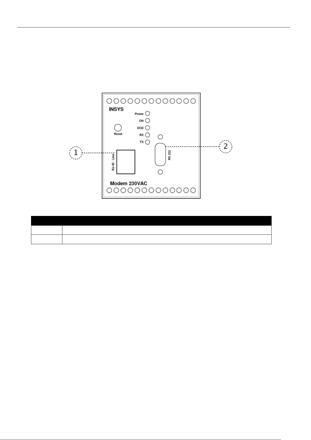
Position
Description
1
Phone connection (RJ45 line socket)
2
Serial Interface (RS-232 socket)
6 Connections
6.1 Front Panel Connections
Figure 2: Connections on the front panel of the device
Table 6: Description of the connections on the front panel of the device
INSYS Modem 56k AC/DC 4.2
Connections
21
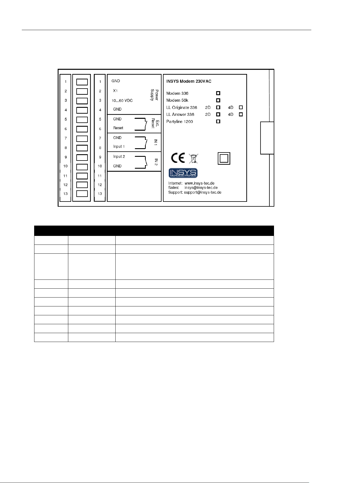
Terminal
Description
Description
1
GND
Ground
2
X1
Reserved
3
10..60V DC
Power supply 10 – 60 V DC (as an alternative or also
redundant to the operation with 100 – 240 V AC at the
terminals 14 and 15)
4
GND
Ground
5
GND
Ground
6
Reset
Reset input
7
GND
Ground
8
Input 1
Alarm input 1
9
Input 2
Alarm input 2
10
GND
Ground
6.2 Terminal Connections on the Top
Figure 3: Connections on the top of the device
Table 7: Description of the connections on the top of the device
Connections
INSYS Modem 56k AC/DC 4.2
22
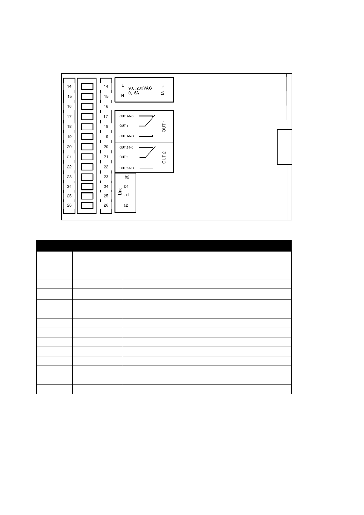
Terminal
Description
Description
14 L Power supply 100 – 240 V AC (as an alternative or also
redundant to the operation with 10 – 60 V DC at the terminals 1 and 3)
15 N N conductor for 100 – 240 V AC power supply
16
NC
Not connected
17
OUT 1-NC
Output 1 normally closed
18
OUT 1
Output 1 root
19
OUT 1-NO
Output 1 normally open
20
OUT 2-NC
Output 2 normally closed
21
OUT 2
Output 2 root
22
OUT 2-NO
Output 2 normally open
23
b2
Looped-through telephone connection
24
b1
Phone line to network provider
25
a1
Phone line to network provider
26
a2
Looped-through telephone connection
6.3 Terminal Connections on the Bottom
Figure 4: Connections on the bottom of the device
Table 8: Description of the connections on the bottom of the device

INSYS Modem 56k AC/DC 4.2
Connections
23
Pin
Signal
Description
1
DCD
Data Carrier Detect
2
RXD
Receive Data
3
TXD
Transmit Data
4
DTR
Data Terminal Ready
5
GND
Ground
6
DSR
Data set ready
7
RTS
Request to send
8
CTS
Clear To Send
9
RI
Ring Indication
6.4 Pin Assignment of the Serial Interface
Figure 5: 9-pin sub-D socket at the device
Table 9: Description of the pin allocation of the sub-D socket
Connections
INSYS Modem 56k AC/DC 4.2
24
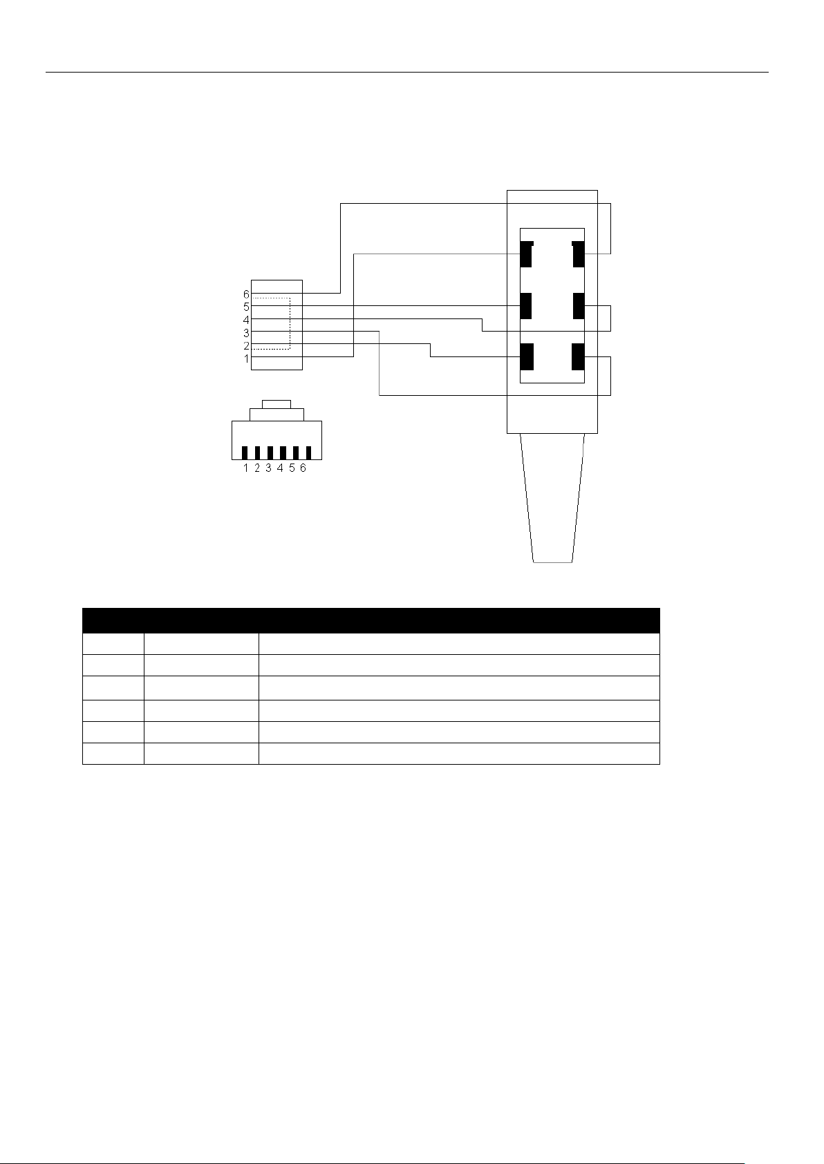
Pin
Signal
Description
1 E Not connected.
2
a2
To connect a phone in series.
3
a1
Incoming phone line (PSTN or PBX).
4
b1
Incoming phone line (PSTN or PBX).
5
b2
To connect a phone in series.
6 W Not connected.
E W
b2 b1
a2 a1
6.5 RJ45 Phone Connection
Figure 6: RJ12 jack connected to TAE socket
Table 10: Layout description of the RJ12 and TAE plugs

INSYS Modem 56k AC/DC 4.2
Function Overview
25
7 Function Overview
The INSYS Modem 56k AC/DC 4.2 provides the following functions:
230V (AC) power supply
The INSYS Modem 56k AC/DC 4.2 has an integrated power supply.
As an alternative, the INSYS Modem 56k AC/DC 4.2 can be supplied
with 230V AC instead of using a DC power supply. In this case, no external power supply will be required. For redundancy purposes, the
INSYS Modem 56k AC/DC 4.2 can additionally be operated with both
power sources
Automatic Baud Rate Detection
The INSYS Modem 56k AC/DC 4.2 will automatically adjust the data
transmission rate, if a connection is made via its serial interface. The
serial transmission rate can be preset for applications for the serial
communication to be able to initialize with a defined baud rate.
Data buffer for serial data transmission
The INSYS Modem 56k AC/DC 4.2 has a fast send and receive buffer
(cache) to adjust the modem to the operating speed of the application.
Bit Direct Mode
The INSYS Modem 56k AC/DC 4.2 can forward incoming data with-
out having any influence on their transmission format.
Hardware and software data flow control
The INSYS Modem 56k AC/DC 4.2 can transmit to the application via
the control lines of the serial interface to interrupt the dataflow, if the
buffers of the INSYS Modem 56k AC/DC 4.2 exceed a certain level.
An application can also prompt the INSYS Modem 56k AC/DC 4.2 via
a control line to interrupt the data flow. As an alternative, the INSYS
Modem 56k AC/DC 4.2 can control the data flow via XOFF/XON characters in the data stream.
Error correction
The INSYS Modem 56k AC/DC 4.2 has the following error correction
protocols: V.42, V.42bis, V.44, MNP2, MNP3, MNP4, and MNP10
Selective Call Answer
The INSYS Modem 56k AC/DC 4.2 can be set to accept only calls
from phone numbers that were previously stored.

Function Overview
INSYS Modem 56k AC/DC 4.2
26
Switch inputs and alarm outputs for SMS dispatch and to establish an
alarm data connection
The INSYS Modem 56k AC/DC 4.2 has two potential-free switch out-
puts, which can be used to switch other functions in an application.
The INSYS Modem 56k AC/DC 4.2 also has digital switch inputs,
which are used to establish connections or to send messages via
SMS and fax.
Sending messages via data connection, SMS or Fax
The INSYS Modem 56k AC/DC 4.2 can send up to 10 previously en-
tered messages to any defined recipient via an AT command. The
dispatch can also be triggered by switching the alarm inputs. Several
transmission paths are possible, such as Fax and SMS.
Pulse input to send up to 10 SMS messages
The SMS to a previously defined recipient can be triggered via the
number of pulses at an alarm input.
Remote configuration
The INSYS Modem 56k AC/DC 4.2 can be configured remotely with
the help of a common modem and a terminal program.
Remote switching of the outputs and queries of the inputs via DTMF
The switching outputs at the INSYS Modem 56k AC/DC 4.2 can be
set remotely with the help of DTMF digits sent from a common
phone. The alarm inputs can be selected via a DTMF phone and queried acoustically.
Access control
The INSYS Modem 56k AC/DC 4.2 can be protected from unauthor-
ized access via a phone connection. An incoming connection must
first be enabled with a password. Using security callback, the INSYS
Modem 56k AC/DC 4.2 calls a previously defined phone number back,
when a call comes in.
Idle connection control with Data Transmit Control
Data Transmit Control enables the INSYS Modem 56k AC/DC 4.2 to
terminate the connection, if no data is transmitted during a defined
state. This will prevent unnecessary costs.
Priority circuit for phones connected in series to the INSYS Modem
56k AC/DC 4.2
The priority circuit prevents that a phone which is connected to the
INSYS Modem 56k AC/DC 4.2 in series is affected by the modem operation. The modem keeps the line free for phone operation. The INSYS Modem 56k AC/DC 4.2 recognizes the states of the phone line at
the individually adjustable voltages.

INSYS Modem 56k AC/DC 4.2
Function Overview
27
Storing the settings in the user profiles
The INSYS Modem 56k AC/DC 4.2 can store the user settings in two
different "profiles". This means that two different configurations can
be stored for special purposes and loaded as needed.
Mounting
INSYS Modem 56k AC/DC 4.2
28
Danger!
Exposed electrical components!
Risk of fatal injury from electric shock.
Prior to the installation, switch the power supply of the
cabinet off and secure it against being switched on again.
Warning!
Moisture and liquids from the environment may seep into
the interior of the INSYS Modem 56k AC/DC 4.2!
Risk of fatal injury from electric shock when touching as
well as fire hazard and damage of the product.
The INSYS Modem 56k AC/DC 4.2 must not be used in wet
or damp environments, or in the direct vicinity of water.
Install the INSYS Modem 56k AC/DC 4.2 at a dry location,
protected from water spray. Disconnect the power supply
before you perform any work on a INSYS Modem 56k
AC/DC 4.2 which may have been in contact with moisture.
Caution!
The device could be destroyed if the wrong power supply is
used!
If the INSYS Modem 56k AC/DC 4.2 is operated with a
power supply that supplies a voltage exceeding the
permissible operating voltage of the INSYS Modem 56k
AC/DC 4.2, the device will be destroyed.
Make sure that you use the suitable power supply. Refer to
the Technical Data section for the proper voltage range of
the INSYS Modem 56k AC/DC 4.2.
8 Mounting
This section describes how to mount the INSYS Modem 56k AC/DC 4.2 to a
DIN rail, connect the power supply and uninstall it again. Observe the
instructions in the "Safety" section of this manual, in particular the "Safety
Instructions for Electrical Installation" for that purpose unconditionally.
INSYS Modem 56k AC/DC 4.2
Mounting
29
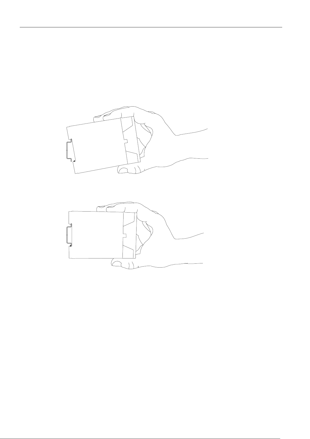
Mounting the device to the DIN rail
How to mount the INSYS Modem 56k AC/DC 4.2 to a DIN rail:
1. Position the device at the DIN rail as seen in the following diagram.
There are two snap-in hooks at the upper and lower edge of the DIN
rail groove of INSYS Modem 56k AC/DC 4.2. Hook the upper one into
place behind the upper edge of the DIN rail.
2. Lift the INSYS Modem 56k AC/DC 4.2 perpendicular to the DIN rail
until the two lower, flexible snap-in hooks engage in the DIN rail.
The INSYS Modem 56k AC/DC 4.2 is now readily mounted.
Mounting
INSYS Modem 56k AC/DC 4.2
30
Danger!
Exposed electrical components!
Risk of fatal injury from electric shock.
Prior to the installation, switch the power supply of the
cabinet off and secure it against being switched on again.
Danger!
Exposed electrical components!
Risk of fatal injury from electric shock.
Prior to the installation, switch the power supply of the
cabinet off and secure it against being switched on again.
Connecting the power supply
The device has already been mounted to the DIN rail.
The power supply is connected and switched off.
1. Connect the ground lead of the power supply to the terminal "GND".
2. Connect the plus pole of the power supply to the terminal for the
power supply.
Disconnecting the power supply
The device is mounted to the DIN rail.
The power supply is connected and switched off.
1. Disconnect the ground lead of the power supply from the terminal
"GND".
2. Disconnect the plus pole of the power supply from the terminal for
the power supply.
The INSYS Modem 56k AC/DC 4.2 is disconnected from the power
supply.
Uninstalling the device from the DIN rail
How to uninstall the INSYS Modem 56k AC/DC 4.2 from a DIN rail in a
switch cabinet:
You will need a Phillips screwdriver with a 4.5 mm blade.
The power supply of the switch cabinet is switched off and secured against
being switched on accidentally.
All cables at the INSYS Modem 56k AC/DC 4.2 are disconnected.
1. Insert the Philips screwdriver into the groove in the bottom of the
INSYS Modem 56k AC/DC 4.2 as shown in the following figure.
 Loading...