

Page 1
ENGLISH
Quick Installation Guide
ECR-LW
www.insys-icom.com
These short operating instructions apply for the following devices of INSYS icom:
▪ ECR-LW300
▪ ECR-LW320
www .insys -icom.com/manual
It is intended for a quick commissioning by the operator. Refer to the associated manual for further information.
This and other associated manuals can be found on our website in the menu Support > Documentation and
Downloads. Scan the QR code above or enter the URL into your web browser.
Te chnical Data
The product is only intended for the use within the permissible technical limits specified in the data sheets. These limits must be observed.
Operating voltage
12 V … 24 V DC (±20%)
LTE frequen cies (4G)
700, 800, 900, 1800, 2100 MHz
bands 1, 3, 8, 20, 28 (ECR-LW300)
700, 850, 900, 1800 MHz
bands 3, 5, 8, 28 (ECR-LW320)
Power consumption
typ. 3 W, max. 7 W
UMTS/HSPA frequencies
(3G)
900, 2100 MHz, bd. 1, 8 (ECR-LW300)
850, 900, 2100 MHz
bands 1, 5, 8 (ECR-LW320)
Level input
HIGH level = 10 ... 24 V
LOW level = 0 ... 5 V
Contact open condition: LOW
GSM/GPRS frequencies
(2G)
900, 1800 MHz (ECR-LW300)
Current consumption input at
HIGH potential
max. 3 mA at 24 V DC
Temperature range
-30 °C … 70 °C
(75 °C extended)
Digital output (open
collector), max. load
24 V (DC), 100 mA
Maximum permissible
humidity
95% non-condensing
Max. voltage drop of the
output in condition ON
< 1 V (DC) at 100 mA load
IP rating
Housing IP40
Outpu t power WLAN (Wi-Fi)
max. 100 mW
Te chnical Boundaries
Max. line lengths for antennas, power supply, serial interfaces, inputs and outputs as well as other signals: 30 m
Cable cross-section: 0.25 … 1.5 mm², flexible lines require end sleeves
Support
If you need further support, please contact your sales partner or INSYS icom support. You can contact our support department via e-mail
under support@insys-icom.de.
De fects Liability Terms
A use other than the intended use, an ignorance of the safety instructions and the documentation, the use of insufficiently qualified
personnel as well as unauthorised modifications exclude the liability of the manufacturer for damages resulting from this. The liability of the
manufacturer ceases to exist.
In tended Use
The product may only be used for the purposes specified in the function overview of the manual. In addition, it may be used for the
following purposes:
▪ Usage and mounting in an industrial cabinet.
▪ Switch ing and data transmission functions in machines according to the machine directive 2006/42/EC.
▪ Usage as data transmission device, e.g. for a PLC.
The product may n ot be used for the following purposes and used or operated under the following conditions:
▪ Use, control, switching and data transmission in machines or systems in explosive atmospheres.
▪ Controlling, switching and data transmission of machines, which may involve risks to life and limb du e to their functions or when a
breakdown occurs.
Page 2
ENGLISH
Quick Installation Guide
ECR-LW
www.insys-icom.com
A
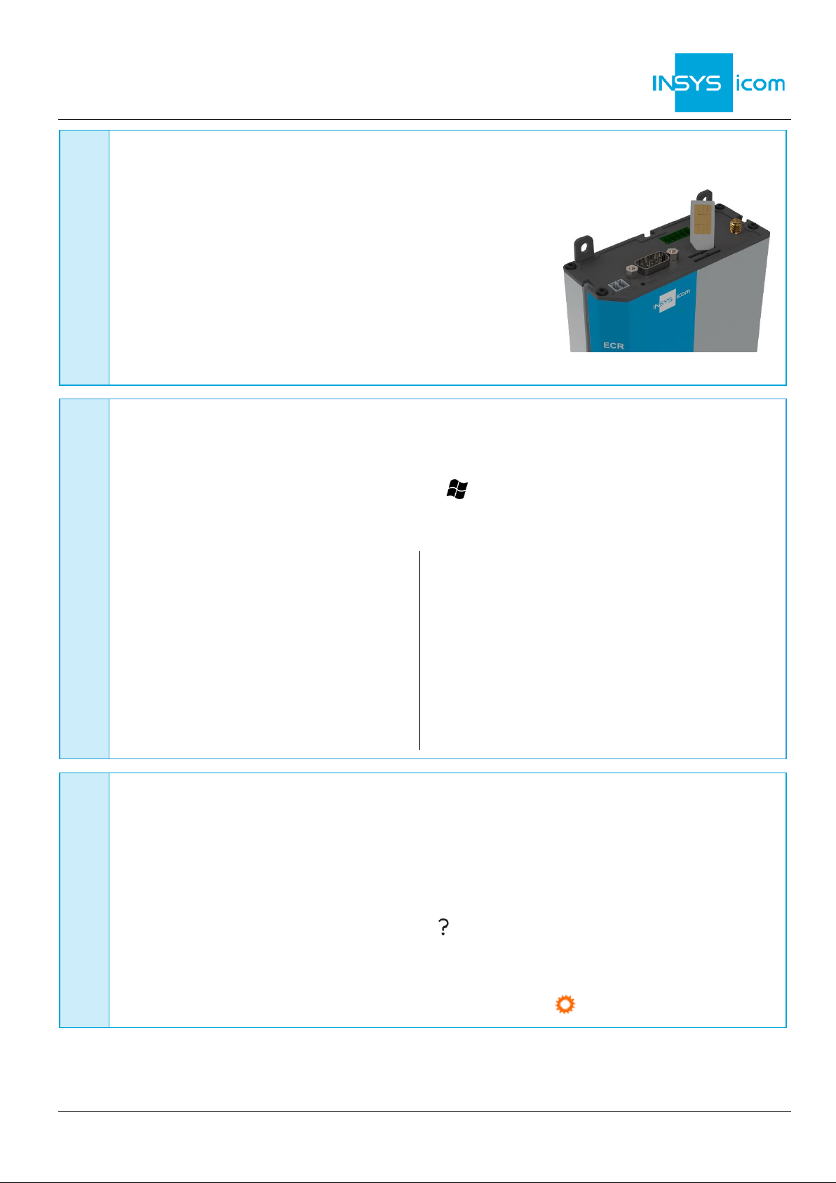
Router connection
1. Insert SIM card (Mini-SIM, 2FF) with contacts facing to the front
and chamfer facing to the router into “SIM 1” slot
2. Connect antenna to connection LTE (SMA (f)).
The screen of the antenna system must
be connected to the protective conductor
when using an outside mounted antenna!
3. Connect supply voltage (12 V … 24 V DC (±20%))
to the terminals V- and V+
4. Connect router (ETH 1) to the configuration PC
5. Connect router (ETH 2) to the network
in which your system is located (local application network)
B
LAN settings of configurations PC (Windows 7)
If a DHCP client is active on the PC, proceed with step C. Otherwise, either enable the
DHCP client or configure a static IP address.
6. Open Network and Sharing Center (e.g. key and search for "sharing")
7. Select LAN connection and Properties
8. Select Internet Protocol Version 4 (TCP/IP) and Properties
Enable DHCP client
9. Obtain an IP address automatically
It is recommended to unplug the
network cable briefly and plug it
again upon activation of the DHCP
client.
Configure a static IP address
Use the following IP address (example):
IP address: 192 . 168 . 1 . 2
Subnet mask: 255 . 255 . 255 . 0
Standard gateway 192 . 168 . 1 . 1
Preferred DNS server: 192 . 168 . 1 . 1
Please note the previous values before
changing the TCP/IP settings to be able
to restore them later.
C
Web interface access
10. Enter IP address of the router in address bar of the browser
(default: 192.168.1.1)
If a proxy server is enabled in your browser, this must be disabled or the IP address of
the router must be added as exception.
11. Login with
Name
(default: insys) and
Password
(icom)
12. Open the Inline Help using the button (Display help text) in the header
The links in the Inline Help lead to the Online Help with further information.
All modified data will only be stored in the opened profile after clicking the
Save
settings
button and become effective upon clicking the (Activate profile) button.
Page 3

ENGLISH
Quick Installation Guide
ECR-LW
www.insys-icom.com
D
Configuration as Internet router via cellular radio
13. In Menu Help > Wizards: Select Startup Wizard
14. Select Internet access via Cellular network
(refer to inline help for WAN over
Ethernet)
The following data can be found in the
contract documents of your SIM card or
can be requested from the provider. The
APNs of popular providers can be
displayed by clinging on .
15. Enter PIN of the SIM card
16. Enter User name and Password for
authentication with the provider (must not
be empty)
17. Enter Access Point Name (APN)
18. Enter IP address of the local application
network
If the router is to be configured for the
icom Connectivity Suite - VPN
(https://connectivity.insys-icom.de), select
icom Connectivity Suite – VPN under VPN connection and enter Customer name and
Device code (from icom Connectivity Suite – VPN, “My VPN Hub” tab). Then, the IP
address in the local network will be assigned by the icom Connectivity Suite - VPN.
19. Click on
Execute wizard
The WAN LED flashes green during connection establishment; as soon as an Internet
connection has been established, it is illuminated green and the Signal LED flashes
green.
If the web interface of the router does not return upon executing the wizard, click on
“Reload” in the browser (or Ctrl+F5).
E
Configuration of access data
User name and password for web interface access of the existing user in the default
settings must be changed to prevent a manipulation of the configuration by
unauthorised persons.
20. Menu Administration > Users: Enter or change User name and Password and select
User group "Read/Write"
21. Store settings in profile with
Save setting
s and activate profile with
A typo during entering or forgetting the configured access data require a reset to
default settings to be able to access the router again.
All essential configuration steps are completed with this. Further configuration depends on your specific
application. Other frequently required settings are available on the following page.
Page 4

ENGLISH
Quick Installation Guide
ECR-LW
Mat. no. 10021497 – Vers. 191219 – Subject to te chnical changes and correction
www.insys-icom.com
Availability of the router upon configuration
The wizard deactivates the configuration network (IP net 1) and assigns ETH1 to the
local application network (IP net 2). In addition, it configures the previous default
address 192.168.1.1 as additional IP address for IP net 2 that the configuration PC still
has access after executing the wizard (if this has not already been assigned in the local
application network).
Using the router as icom Smart Gateway
If the router is to be used as an icom Smart Energy Gateway or icom Smart Machinery
Gateway for example, this is the best time now to install the icom Data Suite required
for this. A wizard is available for this in the
Help
menu. Refer to the Quick Installation
Guide of the icom Data Suite (https://www.insys-icom.com/manual#icom-data-suite) or
the respective Configuration Guide
(https://docs.insys-icom.de/en_icom_data_suite.html).
Resetting the router
If it is necessary to reset the router during configuration, this is possible without losing
the settings.
1. Menu Administration > Reset
2. Click on
Reboot device now
Alternatively, press reset key on the device front once for a short time (soft reset)
Resetting the router to default settings
If the router is to be reset to default settings, it can be reset to delivery state.
1. Menu Administration > Reset: check all options
2. Click on
Reset now
Alternatively, press reset key on the device front three times for a short time within
2 seconds
Resetting and initialising the router
If the router is not available any more for any reason, it can be reset and initialised
(settings do not get lost).
1. Press reset key on the device front for at least 3 seconds (hard reset)
The Inline Help opens upon selecting the button ? (Display help text) and provides helpful
information regarding each individual parameter directly in the web interface.
The Online Help is opened using the links in the Inline Help or in the Help menu in the web
interface and provides further information to the respective topics.
The Configuration Guides are available under https://docs.insys-icom.de and provide helpful
information regarding the integration of your product into your application.
Hereby, INSYS Microelectronics GmbH declares that herein described device types are in compliance with Directives 2014/53/EU
and 2011/65/EU. The full text of the EC Declaration of Conformity is available under www.insys-icom.com/manual.
 Loading...