

Instrutech B-rax 3000 User Manual
InstruTech®, Inc.
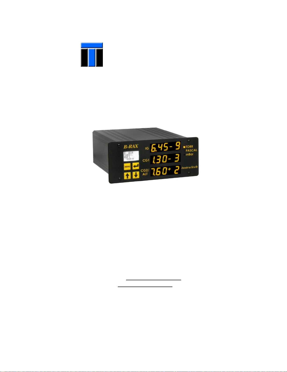
Vacuum Gauge Controller
B-RAX 3000
User Manual
InstruTech, Inc.
1475 S. Fordham St.
Longmont, CO 80503
USA
Phone: +1-303-651-0551
Fax: +1-303-678-1754
E-mail info@instrutechinc.com
www.instrutechinc.com
p/n 000976-106

Instruction Manual B-RAX 3000
Copyright © 2012 by InstruTech®, Inc.
All rights reserved. No part of this work may be reproduced or transmitted in any form or by any means, electronic or mechanical,
including photocopying and recording, or by any information storage or retrieval system, except as may be expressly permitted in
writing by InstruTech, Inc.
Printed in the United States of America
Granville-Phillips® and Convectron® are registered trademarks of Brooks Automation, Inc. Chelmsford, MA.
Conflat® is a registered trademark of Varian, Inc. / Agilent Technologies, Lexington, MA.
Teflon® is a registered trademark of E. I. du Pont de Nemours and Company, Wilmington, DE.
InstruTech, Inc. Page 1

Instruction Manual B-RAX 3000
Table of Contents
Introduction / General Information .................................................................................................................... 4 1
1.1 Description ................................................................................................................................................. 4
1.2 Specifications ............................................................................................................................................. 5
1.3 Dimensions ................................................................................................................................................. 6
1.4 Part Numbers ............................................................................................................................................. 6
Important Safety Information ............................................................................................................................. 7 2
2.1 Safety Precautions - General ...................................................................................................................... 7
2.2 Safety Precautions - Service and operation ............................................................................................... 8
2.3 Electrical Conditions ................................................................................................................................... 8
2.3.1 Proper Equipment Grounding ............................................................................................................ 8
2.3.2 Electrical Interface and Control .......................................................................................................... 9
2.4 Overpressure and use with Hazardous Gases ............................................................................................ 9
2.5 Gases other than Nitrogen / air ................................................................................................................. 9
Installation ........................................................................................................................................................ 11 3
3.1 Mechanical ............................................................................................................................................... 11
3.1.1 Panel Mount ..................................................................................................................................... 11
3.1.2 Rack Mount ...................................................................................................................................... 12
3.2 Electrical Installation ................................................................................................................................ 13
3.2.1 Grounding ......................................................................................................................................... 13
3.2.2 Installation ........................................................................................................................................ 13
3.2.3 IEC 60320 AC Power Input................................................................................................................ 14
3.2.4 Connecting the IGM400 or CCM500 - connector labeled IG............................................................ 14
3.2.5 Connecting the CVG101 - connectors labeled CG1 and CG2 ........................................................... 15
3.2.6 Relay Connectors .............................................................................................................................. 15
3.2.7 Analog Output .................................................................................................................................. 15
3.2.8 Alternate gauge installation ............................................................................................................. 16
InstruTech, Inc. Page 2

Instruction Manual B-RAX 3000
Setup and Operation ......................................................................................................................................... 17 4
4.1 Applying power ........................................................................................................................................ 17
4.2 Emission Current - IGM400 only .............................................................................................................. 18
4.3 Degas - IGM400 only ................................................................................................................................ 18
4.4 IGM400 Filament Material Selection / Venting the Chamber ................................................................. 19
4.5 Overpressure shut down - IGM400 and CCM500 .................................................................................... 20
4.6 User Interface Basics ................................................................................................................................ 21
4.7 Factory-Set Default Parameters ............................................................................................................... 22
4.8 Programming ............................................................................................................................................ 23
4.8.1 SETUP IG - IGM400 ........................................................................................................................... 23
4.8.2 SETUP IG - CCM500 .......................................................................................................................... 27
4.8.3 SETUP CG .......................................................................................................................................... 28
4.8.4 SETUP UNIT ...................................................................................................................................... 30
Using the Gauge with different gases ............................................................................................................... 32 5
5.1 Ion gauge display correction factors for selected gases .......................................................................... 32
5.2 Effects of different gases on convection gauge display ........................................................................... 33
Service ............................................................................................................................................................... 37 6
6.1 Calibration ................................................................................................................................................ 37
6.2 Troubleshooting - IGM400 Operation ...................................................................................................... 37
6.3 Troubleshooting - IGM400 Error Messages ............................................................................................. 38
6.4 Troubleshooting - CCM500 Operation ..................................................................................................... 39
6.5 Troubleshooting - CCM500 Error Messages............................................................................................. 40
6.6 Clearing Errors .......................................................................................................................................... 41
6.7 Programming the B-RAX for the Research screen in the LCD display ...................................................... 42
6.7.1 Research (R & D) Diagnostic Display - IGM400 ................................................................................ 43
6.7.2 Research (R & D) Diagnostic Display - CCM500................................................................................ 46
6.8 Maintenance ............................................................................................................................................ 46
Factory Service and Support ............................................................................................................................. 47 7
Warranty ........................................................................................................................................................... 47 8
InstruTech, Inc. Page 3
Instruction Manual B-RAX 3000
1
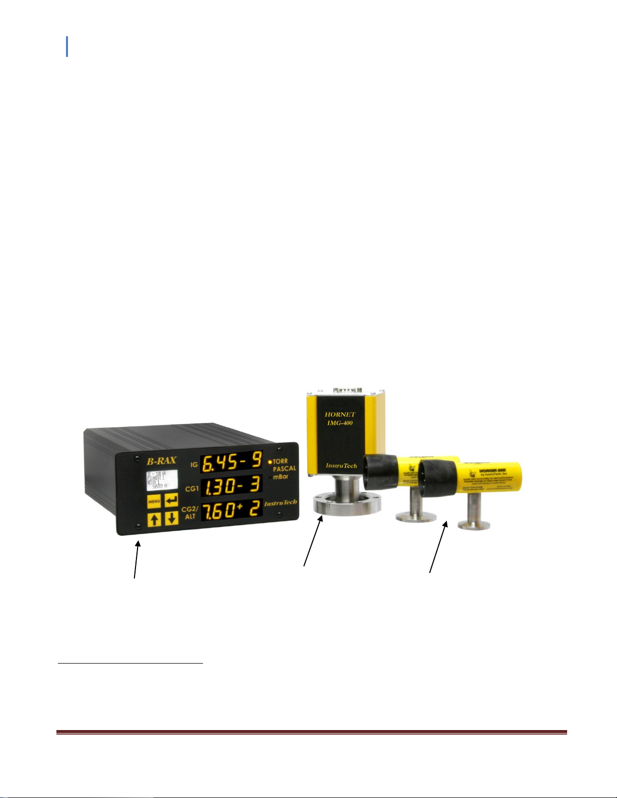
IGM400 or CCM500 Ionization Gauge Module
B-RAX 3000 Vacuum Gauge Controller CVG101 Convection Gauges
(CG1 & CG2)
Typical Components of the complete Vacuum Pressure Measurement System
1
Introduction / General Information 1
1.1 Description
The B-RAX 3000 is a vacuum pressure measurement system which is comprised of the following:
The B-RAX 3000 Vacuum Gauge Controller
Either the IGM400 hot cathode or the CCM500 cold cathode ionization gauge module
One or two InstruTech Worker Bee CVG101 convection enhanced pirani transducers
Cables to interconnect the B-RAX 3000 and point-of-use devices
An alternate vacuum gauge transducer such as a capacitance diaphragm gauge can be used instead of the
second convection gauge. In this case, a two conductor cable to connect the analog output voltage proportional
to pressure measured by that device will be required for connection to the B-RAX 3000 Analog Input connector
located on the back panel.
Typical components of the complete measurement system are shown in the figure below. The B-RAX 3000
provides power and operating control for either the IGM400 or the CCM500 ion gauge module. Additionally, it
provides power and operating control for two convection gauges.
The B-RAX 3000 will also operate the Granville-Phillips® Convectron® convection enhanced pirani gauge transducer.
InstruTech, Inc. Page 4

Instruction Manual B-RAX 3000
measurement range:
(vacuum gauge dependent)
1.0 x 10⁻⁹ to 1000 Torr / 1.3 x 10⁻⁹ to 1333 mbar / 1.3 x 10⁻⁷ Pa to 133 kPa
1.0 x 10⁻⁹ to 5 x 10⁻² Torr when used with the IGM400 hot cathode ionization gauge
1.0 x 10⁻⁸ to 1 x 10⁻² Torr when used with the CCM500 cold cathode ionization gauge
1.0 x 10⁻⁴ to 1000 Torr when used with convection gauges
display pressure
3 independent display channels - 3 digit plus 2 digit exponent LED per channel
displays pressure measurement of one ion gauge, two convection gauges or alternate gauge
engineering units
Torr, mbar, Pa - user selectable
functionality ionization gauge
operates one InstruTech IGM400 or CCM500 ionization vacuum gauge module
convection gauge
operates up to two InstruTech CVG101 convection or Granville-Phillips® Convectron® gauges
alternate gauge (B-RAX 3000 only)
1 alternate 0-10 Vdc analog input from other gauges such as a capacitance manometer
IGM400 filament control
user selectable between filament 1 or 2 using front panel push buttons
IGM400 emission current
100 μA, 4 mA, or automatic switching between 100 μA and 4 mA
IGM400 degas
3 W, electron bombardment
IGM400 overpressure protection
turns off ion gauge at a factory default setting of 5 x 10
-2
Torr
CCM500 overpressure protection
turns off ion gauge at a factory default setting of 1 x 10
-2
Torr
IGM400 status
emission current, relay, filament and degas on/off status displayed on set up screen
temperature
operating; 0 to + 50 oC storage; -40 to + 70 oC
humidity
0 to 95% Relative Humidity, non-condensing
altitude
operating; 6,560 ft. (2,000 m) max storage; 41,000 ft. (12,500 m) max
weight
3.6 lb. (1.62 kg)
housing
aluminum extrusion
analog output (B-RAX 3100 only)
analog output voltage signal is available only on the B-RAX 3100 model. See User Manual for
B-RAX 3100 for specifications and operation.
setpoint relays
3 user programmable single-pole, double-throw (SPDT), 1 A at 30 Vdc resistive, or ac noninductive. Multiple relays assignable to one gauge or one relay per gauge.
source power
100-240 Vac, 50/60Hz, 150 W max, universal input power
RF/EMI protection
CE compliant
environmental
RoHS compliant
Whether you choose the IGM400 or the CCM500, you will enjoy the benefits of InstruTech’s novel design
approach for this multiple transducer vacuum pressure measurement system. Departing from the traditional
vacuum gauge controller approach of the past, the B-RAX 3000 provides a compact, low power, cost effective
solution for controlling the operation of one ionization gauge (IG) module and two convection enhanced pirani
transducers (often referred to as a Convection Gauge or CG). The traditional controller designs incorporate the
IG power supplies and ion current measurement circuitry inside a separate controller unit requiring connection
to the IG transducer via complex cabling systems. The B-RAX 3000 system, utilizing the design concept of
integrating the power, control and ion current measurement circuitry inside the IGM400 and CCM500 devices
connected at the point of vacuum measurement, minimizes overall complexity, cost and space requirements.
The B-RAX 3000, a controller unit capable of controlling multiple gauge transducers, is either rack or instrument
panel mountable. The clean, space saving design of the B-RAX 3000 enclosure lends itself to an appealing device
for bench-top use. Optional industry standard 19-inch, 2U high rack-mount panels are available to mount the
B-RAX into rack enclosures.
1.2 Specifications
NOTICE - For important information about the CVG101 Worker Bee™ convection gauge, CCM500 cold cathode ionization
gauge and IGM400 Hornet™ hot cathode ionization gauge products, please refer to the User Manual for each of these
products. Read the User Manuals in their entirety for any device you intend to connect to the B-RAX 3000 prior to
connecting and using the external devices and cables that the B-RAX 3000 is intended to be used with.
InstruTech, Inc. Page 5

Instruction Manual B-RAX 3000
B-RAX3000 (3 display channels, 3 set-point relays, no analog output, one alternate analog input from a CDG)
(includes mating interface connectors, power cord & plug.)
B-RAX 3000
IGM400 or CCM500 ionization gauge
See IGM400 or CCM500 Hornet™ ionization gauge User Manuals
CVG101 convection gauge
See CVG101 Worker Bee™ convection gauge User Manuals
Cables IGM400 and CCM500
ionization gauge cable
CVG101 convection
gauge cable
10 FT (3 m)
BXC400-1-10F
CB421-1-10F
25 FT (8m)
BXC400-1-25F
CB421-1-25F
50 FT (15m)
BXC400-1-50F
CB421-1-50F
> 50 FT
Consult factory
Consult factory
Optional Rack Mount Adapter
Rack Mount adapter panel for installation of one B-RAX in center of a 19 inch rack
000849
Rack Mount adapter panel for installation of two B-RAX side-by-side in a 19 inch rack
001007
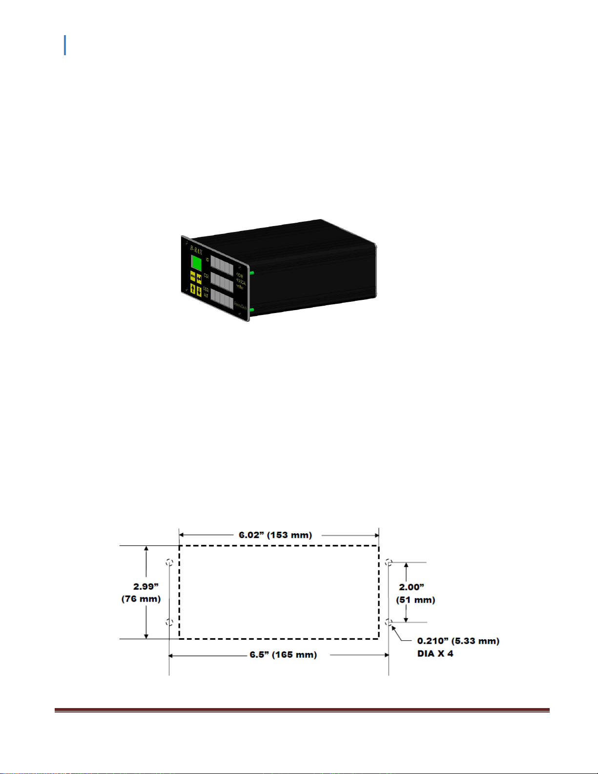
1.3 Dimensions
Front View
Side View
1.4 Part Numbers
InstruTech, Inc. Page 6

Instruction Manual B-RAX 3000
WARNING
Important Safety Information 2
InstruTech has designed and tested this product to provide safe and reliable service, provided it is installed and
operated within the strict safety guidelines provided in this manual. Please read and follow all warnings and
instructions.
To avoid serious injury or death, follow the safety information in this document. Failure to comply with these
safety procedures could result in serious bodily harm, including death, and or property damage.
Failure to comply with these warnings violates the safety standards of installation and intended use of this
instrument. InstruTech, Inc. disclaims all liability for the customer’s failure to comply with these instructions.
Although every attempt has been made to consider most possible installations, InstruTech cannot anticipate
every contingency that arises from various installations, operation, or maintenance of the module. If you have
any questions about the safe installation and use of this product, please contact InstruTech.
This device meets FCC part 15 requirements for an unintentional radiator, class A.
2.1 Safety Precautions - General
Hazardous voltages are present with this product during normal operation. The product should never be
operated with the covers removed unless equivalent protection of the operator from accidental contact with
hazardous internal voltages is provided.
WARNING! There are no operator serviceable parts or adjustments inside the product enclosure; refer
servicing to service trained personnel.
Do not modify this product or substitute any parts without authorization of qualified InstruTech service trained
personnel. Return the product to an InstruTech qualified service and repair center to ensure that all safety
features are maintained. Do not use this product if unauthorized modifications have been made.
WARNING! Source power must be removed from the product prior to performing any servicing.
After servicing this product, ensure that all safety checks are made by a qualified service person. When
replacement parts are required, ensure that the parts are specified by InstruTech. Substitutions of nonqualified parts may result in fire, electric shock or other hazards. Use of unauthorized parts or modifications
made to this product will void the warranty.
To reduce the risk of fire or electric shock, do not expose this product to rain or moisture. These products are
not waterproof and careful attention must be paid to not spill any type of liquid onto these products. Do not
use these products if they have been damaged. Immediately contact InstruTech, Inc. to arrange return of the
product if it is damaged.
InstruTech, Inc. Page 7

Instruction Manual B-RAX 3000
Due to the possibility of corrosion when used in certain environmental conditions, it is possible that the
product’s safety could be compromised over time. It is important that the product be periodically inspected for
sound electrical connections and equipment grounding. Do not use if the equipment grounding or electrical
insulation has been compromised.
2.2 Safety Precautions - Service and operation
Ensure the enclosure of the B-RAX is connected directly to a good quality earth ground.
Ensure that the vacuum port on which the vacuum gauge sensors are mounted is electrically grounded.
Use an appropriate power source of 100-240 Vac, 50/60Hz or 12 to 30 Vdc, 150 W.
Turn off power to the unit before attempting to service the controller.
Turn off power to the unit if a cable or plug is damaged or the product is not operating normally according to
this instruction manual. Contact qualified InstruTech service personnel for any service or troubleshooting
condition that may not be covered by this instruction manual.
It is important that the product be periodically inspected for sound electrical connections and equipment
grounding. Do not use if the equipment grounding or electrical insulation has been compromised.
Do not use if the unit has been dropped or the enclosure has been damaged. Contact InstruTech for return
authorization and instructions for returning the product to InstruTech for evaluation.
2.3 Electrical Conditions
WARNING! When high voltage is present in any vacuum system, a life threatening electrical shock hazard
may exist unless all exposed electrical conductors are maintained at earth ground potential. This applies to all
products that come in contact with the gas contained in vacuum chambers. An electrical discharge within a
gaseous environment may couple dangerous high voltage directly to any ungrounded conductor of electricity.
A person could be seriously injured or killed by coming in contact with an exposed, ungrounded electrical
conductor at high voltage potential. This condition applies to all products that may come in contact with the gas
inside the vacuum chamber (vacuum/pressure containment vessel).
2.3.1 Proper Equipment Grounding
WARNING! Hazardous voltages that could seriously injure or cause death are present in many vacuum
processes. Verify that the vacuum connection ports on which the ion gauge and the convection gauges are
mounted are electrically grounded. Consult a qualified Electrician if you are in doubt about your equipment
grounding. Proper grounding of your equipment is essential for safety as well as intended operation of the
equipment. The vacuum gauge transducers and enclosure of any control module must be connected directly to
a good quality equipment earthing conductor. Use a ground lug on the vacuum connection flange of the
pressure measurement devices if necessary.
InstruTech, Inc. Page 8

Instruction Manual B-RAX 3000
WARNING! In order to protect personnel from electric shock and bodily harm, shield all conductors
which are subject to potential high voltage electrical discharges in or around the vacuum system.
2.3.2 Electrical Interface and Control
It is the user’s responsibility to ensure that the electrical signals from this product and any connections made to
external devices, for example, relays and solenoids, are used in a safe manner. Always double check the system
set-up before using any signals to automate your process. Perform a hazardous operation analysis of your
system design and ensure safeguards and personnel safety measures are taken to prevent injury and property
damage.
2.4 Overpressure and use with Hazardous Gases
WARNING! Install suitable protective devices that will limit the level of pressure inside your vacuum
chamber to less than what the vacuum chamber system components are capable of withstanding.
In cases where an equipment failure could cause a hazardous condition, always implement fail-safe system
operation. For example, use a pressure relief device in an automatic backfill operation where a malfunction
could result in high internal pressures if the pressure relief device was not installed on the chamber.
The vacuum gauge transducers used with this product are not intended for use at pressures above 20 psia (1000
torr); DO NOT exceed 35 psig (< 2 ½ bars) pressure inside the sensor. If your chamber goes to higher pressures,
you should install an isolation valve or pressure relief device to protect the gauge tube from overpressure
conditions. With some fittings, actual safe overpressure conditions may be lower; for example, a quick-connect,
O-ring compression fitting may forcibly release the gauge tube from the vacuum chamber fitting with only a few
psi over local uncorrected barometric (atmospheric) pressure.
CAUTION! If the internal pressure of a vacuum gauge device is allowed to increase above local
uncorrected barometric pressure (atmospheric pressure side), vacuum fittings may release and possible
overpressure conditions may cause leaks that would allow the gas inside the gauge tube to release into the
atmosphere of the surrounding environment. Toxic, pyrophoric and flammable gases are examples of
hazardous gases that if allowed to leak out of the vacuum/pressure containment vessel into the atmospheric
environment, could cause bodily injury and possible damage to equipment. Never expose the gauge tube
internal volume to pressure above local atmospheric pressure when using hazardous gases.
2.5 Gases other than Nitrogen / air
WARNING! Do not attempt to use with gases other than nitrogen (N2) or air without referring to correction
factor data tables.
InstruTech gauges and modules are calibrated for direct readout of nitrogen or air. Do not attempt to use with
other gases such as argon (Ar) or carbon dioxide (CO2) unless you have applied correction factors to both the
displayed pressure and the analog output to determine the true measured pressure. This is particularly critical
when using convection gauges to measure pressure of gases other than N2/Air.
InstruTech, Inc. Page 9

Instruction Manual B-RAX 3000
WARNING! Do not use the IGM400 in an explosive atmosphere or in the presence of flammable gases,
vapors or fumes. Do not use the IGM400 to measure the pressure of explosive or combustible gases or gas
mixtures. The sensor filaments operate at incandescent temperatures and could become an ignition source.
This could cause an explosion which could result in serious injury or death.
WARNING! Do not use the CVG101 in an explosive atmosphere or in the presence of flammable gases,
vapors or fumes. Do not use the CVG101 to measure the pressure of explosive or combustible gases or gas
mixtures. The sensor wire in the gauge normally operates at 125 oC, but if malfunction should occur, the wire
temperature could exceed the ignition temperature of certain combustible gases and gas mixture. This could
cause an explosion which could result in serious injury or death.
InstruTech, Inc. Page 10
Instruction Manual B-RAX 3000
Installation 3
3.1 Mechanical
The B-RAX 3000 is intended for indoor use only.
The B-RAX is offered as a space saving half rack design. It may also be used as a bench top device or easily
installed in an instrument panel. Optional EIA-standard rack mount panels are available for either full rack or
dual, side-by-side rack mount installation.
B-RAX 3000 Vacuum Gauge Controller Installation
3.1.1 Panel Mount
To install the B-RAX in a rack or instrument control panel follow the steps outlined below:
1. Make a cutout in your rack panel or instrument control panel as shown in the drawing below. Be sure to
allow clearance behind the panel for the instrument as well as connectors and cables at the back of the
instrument. Optional EIA-standard, 19-inch, 2U height rack mount panels are available from InstruTech, Inc.
The optional rack mount panels are provided with panel cutouts and mounting holes to allow efficient mounting
of your B-RAX unit.
Panel Cutout
InstruTech, Inc. Page 11
Instruction Manual B-RAX 3000
2. Drill four guide holes on each side of the panel cut out (two on each side) with dimensions as shown in the
panel cut-out drawing above.
3. Slide the B-RAX into the panel hole cut-out. Guide the four studs on the back of the B-RAX front panel face
plate thru the four holes next to the panel cut-out.
4. Use four # 10-32 Hex Nut (provided with instrument) to tighten the B-RAX to the panel.
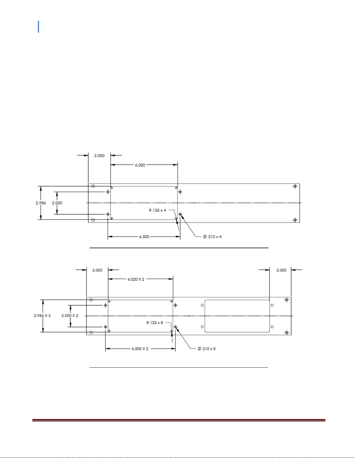
3.1.2 Rack Mount
Optional EIA-standard 19-inch wide, 2U height rack mount panels available from InstruTech:
Single cut-out panel (InstruTech p/n 00849) - All dimensions in inches
Dual cut-out panel (InstruTech p/n 001007) - All dimensions in inches
The single cut-out and dual cut-out rack mountable panels shown above are available from InstruTech. Panel
color matches the front panel of B-RAX units. Screws for mounting to rack enclosure are user provided.
InstruTech, Inc. Page 12
Instruction Manual B-RAX 3000
3.2 Electrical Installation
3.2.1 Grounding
Be sure the vacuum gauges and the rest of your vacuum system are properly grounded to protect
personnel from shock and injury. Be aware that some vacuum fittings, especially those with O-rings when not
used with metal clamps, may not produce a good electrical connection between the gauge and the chamber it is
connected to. Use a ground lug on the vacuum connection flange of the pressure measurement device if
necessary. The B-RAX control unit should be connected to earth ground via a good quality equipment earthing
conductor. The IEC 60320 type AC Mains power cord set provided with your B-RAX is intended to connect
facility earth ground to the B-RAX enclosure. It is encouraged that you connect a separate 12-AWG earthing
conductor between a known facility earth ground connection and the location marked with the earth ground
symbol (via the green colored screw provided) on the back panel of the B-RAX.
3.2.2 Installation
A good, recommended practice is to remove power from any cable prior to connecting or disconnecting it. The
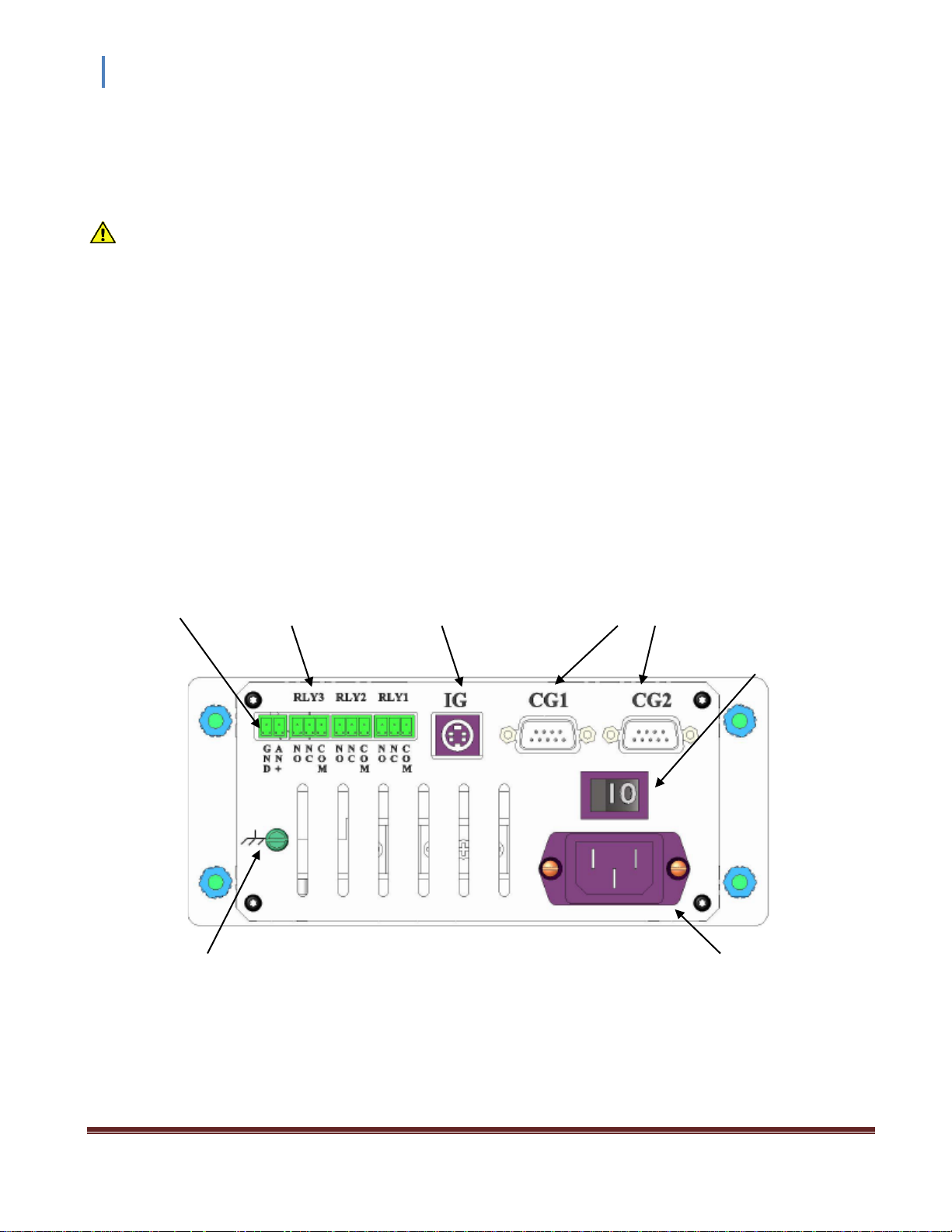
electrical connections for the B-RAX are located on the back panel of the device as shown below.
Analog input 3 Relay Ion Gauge 2 Convection Gauge
connector connectors connector connectors
AC Mains Power
Switch
B-RAX Back Panel Electrical Connections
Aux. Equipment IEC 60320
Earthing Connection AC Power Input
InstruTech, Inc. Page 13

Instruction Manual B-RAX 3000
3.2.3 IEC 60320 AC Power Input
Universal AC power cord input connector. The B-RAX accepts AC Mains power from 100 to 240 VAC, 50/60Hz,
nominal. The B-RAX controller is provided with a NEMA 5-15P power cord set with North America 115 Vac plug
and mating IEC60320 plug for connection to the B-RAX AC Power Input connector. The IEC 60320 power inlet
connector on the B-RAX will allow international cord sets with 100-240 Vac power plugs commonly used in other
regions to be used directly. Single phase AC Mains power and protective earthing connections are provided by
the IEC 60320 compatible power cord set. Set the AC Power Switch to OFF (0) before connecting power cord.
3.2.4 Connecting the IGM400 or CCM500 - connector labeled IG
Good, recommended practice is to remove power from any cable prior to connecting or disconnecting it. Use
the cable/connector assembly provided by InstruTech for connection to the B-RAX vacuum gauge controller.
The programming parameters for the IGM400 and CCM500 module are transmitted between the module and
the B-RAX immediately during initial AC Mains Power ON condition. If an IGM400 or CCM500 module is
swapped or a cable from one module is moved and reconnected to a different module, the B-RAX considers the
first module connected at power ON to be the device it is communicating with.
Changing cables from one device to another when power is applied to the module is not only bad electronics
handling procedure, it is not advised and, if done by the user of this equipment, may lead to erroneous
measurement results, a hazardous situation, equipment damage and possible operator injury .
CAUTION! Possible damage to property and injury to personnel may result if connections to the Ion
Gauge (IG) connector are made while power is applied to the B-RAX control unit. DO NOT connect, disconnect
or reconnect the cable from the B-RAX back panel IG connector to either the IGM400 or the CCM500 module
when power is applied to the B-RAX. Switch the AC Mains Power Switch on the back panel of the B-RAX to
OFF (0) prior to either disconnecting or reconnecting cables to external devices such as the IGM400 and CCM500
modules.
The DE-9 D-subminiature end of the InstruTech cable assembly for connecting the IGM400 or the CCM500 ion
gauge module to the B-RAX is connected to either the IGM400 or CCM500 module. The mini-DIN connector end
of this cable connects to the connector labeled IG on the back panel of the B-RAX
InstruTech, Inc. Page 14
 Loading...