

Instruo vinca User Manual
vincâ
Dual VCA
User Manual

Contents
3
Description / Features
4
Installation / Specifications
5
Overview
6
Channel One
8
Channel Two
11
Linking vincâs
12
Patch Examples
2

Description
We’ve all heard the phrase, “You can never have enough VCAs.”
We know it and we totally get it.
With the Instruō vincâ, this truly is the case.
vincâ is a two channel voltage controlled amplifier with both parallel
and series routing capabilities. Each VCA has a different architecture
allowing them to offer unique functionality that both contrasts and
compliments one another.
The top VCA has Input Bias and Input Attenuverter controls over its
four-quadrant multiplication capabilities.
The bottom VCA has an amplitude control that also acts as a CV
attenuator when control voltage is applied. The bottom VCA includes a
Shape control that morphs between linear and exponential
response curves.
Each channel can be used independently (in parallel) or can be
cascaded (in series), by flipping the Mode Switch.
in
Chain one v
and routing schemes dispersed throughout your entire system.
câ to another (and another, and another!) to add mixing
Features
• Two channel VCA with separate functionality per channel
• Input bias and attenuverter
• Linear and exponential response curves
• Parallel and series configuration
• Infinitely chainable to additional vincâ modules
3

Installation
1. Confirm that the Eurorack synthesizer system is powered off.
2. Locate 4 HP of space in your Eurorack synthesizer case.
3. Connect the 10 pin side of the IDC power cable to the 2x5 pin
header on the back of the module, confirming that the red stripe on
the power cable is connected to -12V.
4. Connect the 16 pin side of the IDC power cable to the 2x8 pin
header on your Eurorack power supply, confirming that the red
stripe on the power cable is connected to -12V.
in
5. Mount the Instruō v
6. Power your Eurorack synthesizer system on.
câ in your Eurorack synthesizer case.
Note:
This module has reverse polarity protection.
Inverted installation of the power cable will not damage the module.
Specifications
• Width: 4HP
• Depth: 35mm
• +12V: 30mA
• -12V: 25mA
4

in
IO
I O
VCA 1
VCA 2
LINEAR TO EXPONENTIAL SHAPING
UNITY GAIN
DUAL VCA
PARALLEL
SIGNAL ROUTING
SERIES
vincâ | 'vIŋkə | noun (horticulture) genus of small flowering plants
commonly known as the periwinkle
Channel 1
11
Front
Back
51
2
4
3
7
9
8
Channel 2
12
6
10
13
Key
1. Input 1A
2. Input Bias
3. Input Attenuverter
4. Input 1B
5. Output 1
6. Input 2
7. CV Input
8. Amplitude/CV Attenuverter
9. Shape
10. Output 2
11 . Mode Switch
12. Input Back Jack
13. Output Back Jack
5
Channel One
Input 1a: DC coupled input for channel 1.
• This input will accept both audio and control voltage signals.
• Channel 1 functions as a four quadrant multiplier. Signals at
Input 1a will multiply with signals at Input 1b.
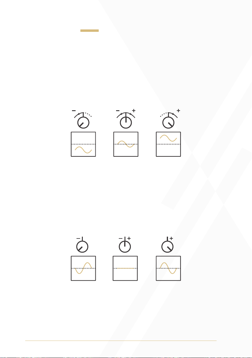
Input Bias: The Input Bias will offset signals present at Input 1a.
• Turning the knob anticlockwise will sum a negative DC offset with the
signal present at Input 1a.
• Turning the knob clockwise will sum a positive DC offset with the
signal present at Input 1a.
Input Attenuverter: The Input Attenuverter scales and inverts the signal
present at Input 1a.
• If there is no control voltage patched at Input 1b, it receives a
normalled +5V reference signal. The scaled and/or inverted signal
from Input 1a sums with the Bias and multiplies with this unity gain
reference signal.
6
 Loading...