

Instruo Cs-L User Manual
Cš-L
Complex Oscillator
User Manual

Contents
3
Description / Features
4
Installation / Specifications
5
Overview
7
Oscillators
12
Frequency/Pitch
13
Link Button
14
Frequency Modulation
15
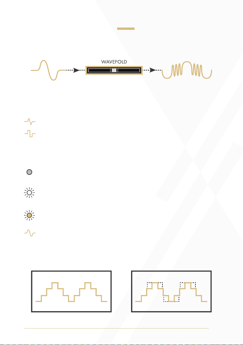
Wavefolding
17
Oscillator Synchronisation
19
Amplitude Modulation
21
Internal Modulation Routing
26
Patch Examples
2

Description
The Instruō Cš-L is a dual analogue oscillator optimised for generation of
complex waveforms. It features two contrasting discrete circuit oscillators
that are normalled to one another, offering a variety of simultaneous
modulation routings. The resulting harmonic timbres sit far beyond the
realms of traditional subtractive synthesis.
It expands upon the classic complex oscillator paradigm prominent
in the West Coast synthesis philosophy. Typical cross modulation is
expanded upon with inclusion of signal multiplication/amplitude
modulation, a wavefolder per oscillator, final waveform symmetry
biasing, classic and contemporary PWM, a global modulation index
bus, and a digitally-controlled routing scheme that can be configured
on-the-fly.
With the two separate oscillator cores, simultaneous access to all
included waveforms, and the ability for bi-directional modulation, the
Cš-L truly allows the user to shape sound like never before.
Features
• Two independent contrasting cored analogue oscillators
• Wavefolder per oscillator
• Waveform symmetry biasing
• 1V/Oct linking for parallel tracking
• Four-quadrant signal multiplication/amplitude modulation
• Internal oscillator sync capabilities
• Digitally-controlled internal modulation routing
• Global modulation index bus
• LFO capabilities
• Sub-square modes
3

Installation
1. Confirm that the Eurorack synthesizer system is powered off.
2. Locate 26 HP of space in your Eurorack synthesizer case.
3. Connect the 10 pin side of the IDC power cable to the 2x5 pin
header on the back of the module, confirming that the red stripe on
the power cable is connected to -12V.
4. Connect the 16 pin side of the IDC power cable to the 2x8 pin
header on your Eurorack power supply, confirming that the red
stripe on the power cable is connected to -12V.
5. Mount the Instruō Cš-L in your Eurorack synthesizer case.
6. Power your Eurorack synthesizer system on.
Note:
This module has reverse polarity protection.
Inverted installation of the power cable will not damage the module.
Specifications
• Width: 26 HP
• Depth: 35mm
• +12V: 200mA
• -12V: 80mA
4
Cš-L | si:-əz-El | proverb (derivative) “complex sauce-later”
8
9
24
4
5
6
7
3
1
2
10
11
27
12
13
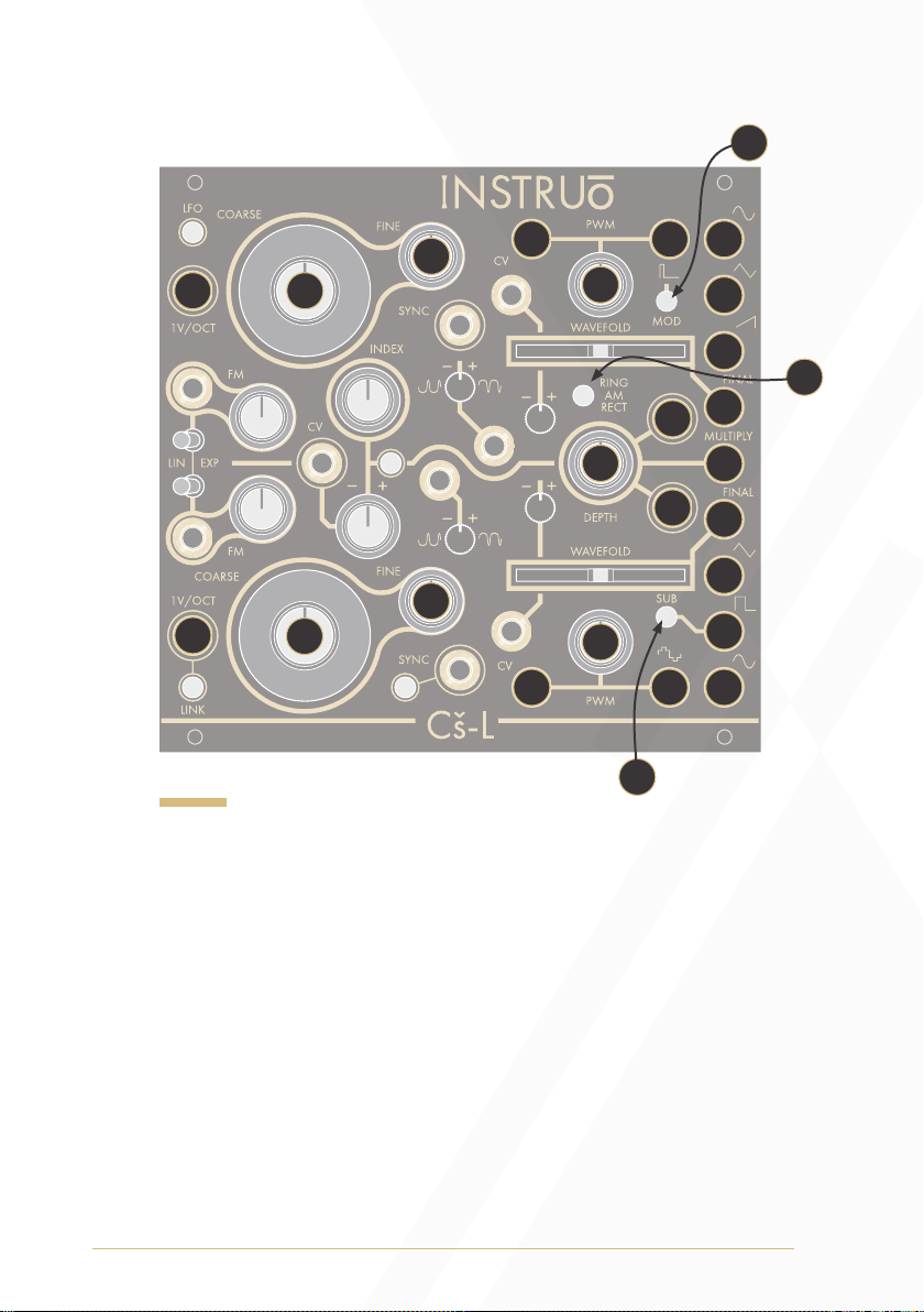
Key
1. Osc A 1V/Oct Input
2. Osc A Coarse Frequency
3. Osc A Fine Frequency
4. Osc A Sine Output
5. Osc A Triangle Output
6. Osc A Sawtooth Output
7. Osc A Final Output
8. Mod Button
9. Osc A PWM Output
10. Osc A PWM CV Input
11 . Osc A PWM
12. Osc B 1V/Oct Input
13. Osc B Coarse Frequency
14. Osc B Fine Frequency
26
14
22
21
17
15. Osc B Sine Output
16. Osc B Square Output
17. Sub Button
18. Osc B Triangle Output
19. Osc B Final Output
20. Osc B PWM Output
21. Osc B PWM CV Input
22. Osc B PWM
23. Multiply Output
24. Multiply Modulator Input
25. Multiply Carrier Input
26. Depth
27. Ring/AM/Rect Button
25
20
23
19
18
16
15
5
28
39
43
45
40
30
29
31
37
32
34
33
35
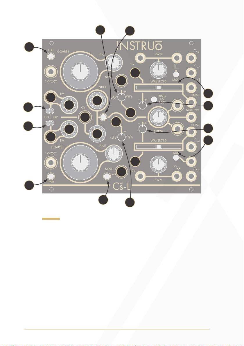
Key
28. LFO Button
29. Osc A Lin/Exp Toggle
30. Osc A FM Input
31. Osc A FM Attenuator
32. Osc B Lin/Exp Toggle
33. Osc B FM Input
34. Osc B FM Attenuator
35. Link Button
36. Index Knob
37. Index CV Input
38. Index Attenuverter
39. Index Button
40. Hard Sync Input
36
38
42
47
46
44
49
51
52
50
41
48
41. Soft Sync Input
42. Sync Button
43. Osc A Symmetry Bias Attenuverter
44. Osc A Symmetry Bias Input
45. Osc A Wavefold CV Input
46. Osc A Wavefold Annenuverter
47. Osc A Wavefold Fader
48. Osc B Symmetry Bias Attenuverter
49. Osc B Symmetry Bias Input
50. Osc B Wavefold CV Input
51. Osc B Wavefold Annenuverter
52. Osc B Wavefold Fader
6

Oscillators
Oscillators A and B share various similarities, but they utilise very
different circuitry architectures. Oscillator A features a sawtooth core
circuit while Oscillator B features a triangle core circuit. This contrast
in cores result in slight variations in the harmonic content of each
oscillators’ available waveforms and their strengths and weaknesses.
In short, sawtooth core circuits can do certain things better than triangle
core circuits, and vice versa. The Cš-L offers the best of both worlds
It is important to note that, because of their different architectures and
configurations, each oscillator has a different global frequency range.
This means that matching pointer positions on the Coarse and Fine
frequency knobs will not necessarily result in matching
output frequencies.
The peak-to-peak amplitude of the various waveform outputs differ from
each other slightly. The reference point is 10Vpp on the sawtooth wave.
The other signal amplitudes were purposefully chosen to give a more
balanced perceived loudness over a musical range. This effect is most
prominent between the more harmonically rich waveforms.
7
Oscillator A (Sawtooth Core)
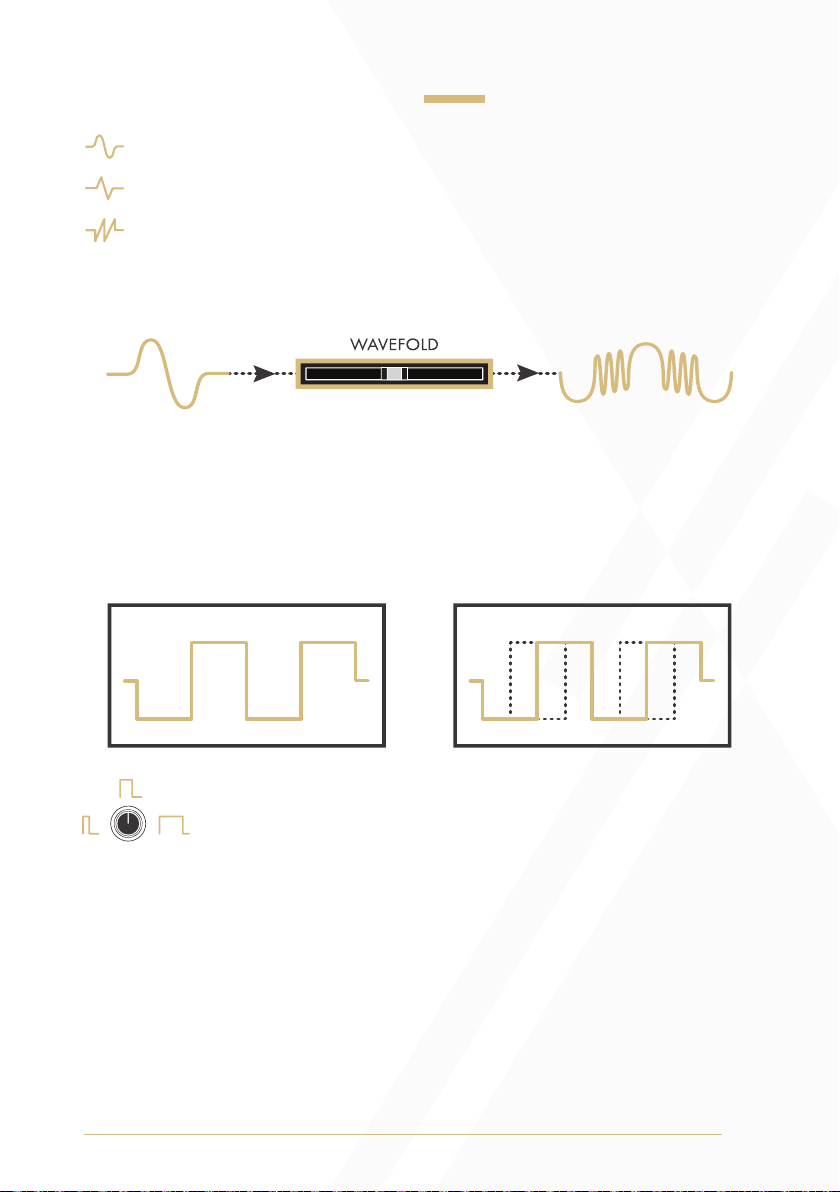
OSC A PWM
VARIABLE DUTY CYCLE
Sine Output: Sine waveform output.
Triangle Output: Triangle waveform output.
Sawtooth Output: Sawtooth/Ramp waveform output.
Final Output: Final waveform output.
• The waveform is determined by the Wavefold parameter and the
Symmetry Bias Attenuverter.
PWM Output: Pulse width modulation waveform output.
PWM: The PWM knob controls the duty cycle ratio of the
pulse width modulation waveform.
• Turning the knob clockwise will increase the +/– ratio of the
pulse wave.
• Turning the knob anticlockwise will decrease the +/– ratio of the
pulse wave.
• The range of the PWM knob was chosen to always result in a signal
with an audible duty cycle when used without external
control voltage.
8

PWM CV Input: The PWM CV Input is a bipolar control voltage
input for the PWM parameter.
• Control voltage sums with the PWM knob position.
• Input range: -/+5V.
• Note that with external control voltage extending the controllable
range of the duty cycle, audibility of the signal will drop when
pushed beyond 0% and 100%.
LFO Button: The LFO Button will switch Oscillator A to sub-audio
range frequencies.
If the LFO Button is unilluminated, Oscillator A will output audio
range frequencies.
• Oscillator A will continue to track 1V/Octave when set to
LFO Mode.
• The LFO will reset with every rising edge signal present at the Hard
Sync Input of Oscillator A.
If the LFO Button is illuminated white, Oscillator A will output
sub-audio range frequencies.
LFO Hard Sync
9
Oscillator B (Triangle Core)
OSC B PWM
VARIABLE DUTY CYCLE
Final Output: Final waveform output.
• The waveform is determined by the Wavefold parameter and the
Symmetry Bias Attenuverter.
Triangle Output: Triangle waveform output.
Square Output: Square waveform output.
Sub Button: The Sub Button determines the octave of the
Square Output.
If the Sub Button is unilluminated, the square waveform is set to the
fundamental frequency of Oscillator B.
If the Sub Button is illuminated white, the square waveform is set to
one octave below the fundamental frequency of Oscillator B.
If the Sub Button is illuminated amber, the square waveform is set
to two octaves below the fundamental frequency of Oscillator B.
Sine Output: Sine waveform output.
PWM Output: Stepped triangle waveform output.
10

PWM: The PWM knob controls the width of the upper and lower pulses
of the stepped triangle waveform.
• Turning the knob clockwise will increase the width of the upper and
lower pulses.
• Turning the knob anticlockwise will decrease the width of the upper
and lower pulses.
• The range of the PWM knob was chosen to always result in a signal
with an audible duty cycle when used without external
control voltage.
PWM CV Input: The PWM CV Input is a bipolar control voltage input
for the PWM parameter.
• Control voltage sums with the PWM knob position.
• Input range: -/+5V.
• Note that with external control voltage extending the controllable
range of the duty cycle, audibility of the signal will drop when
pushed beyond 0% and 100%.
11

Frequency/Pitch
Coarse: The Coarse knob controls the fundamental frequency of the
oscillator. It determines the pitch of all corresponding waveforms.
• Turning the knob clockwise will increase the frequency.
• Turning the knob anticlockwise will decrease the frequency.
Fine: The Fine knob is used for minute control of the oscillator’s
fundamental frequency and is relative to the frequency value set by the
Coarse knob. It also determines the pitch of all
corresponding waveforms.
• Turning the knob clockwise will increase the frequency.
• Turning the knob anticlockwise will decrease the frequency.
1V/Oct Input: The 1V/Oct Input is a bipolar control voltage input that
is calibrated to 1V per octave.
• This is traditionally used for frequency control (musical pitch) sent
from a sequencer or keyboard.
• Control voltage is added to the summed values set by the Coarse
and Fine knobs.
12
OSC A
OSC B
OSC A
OSC B
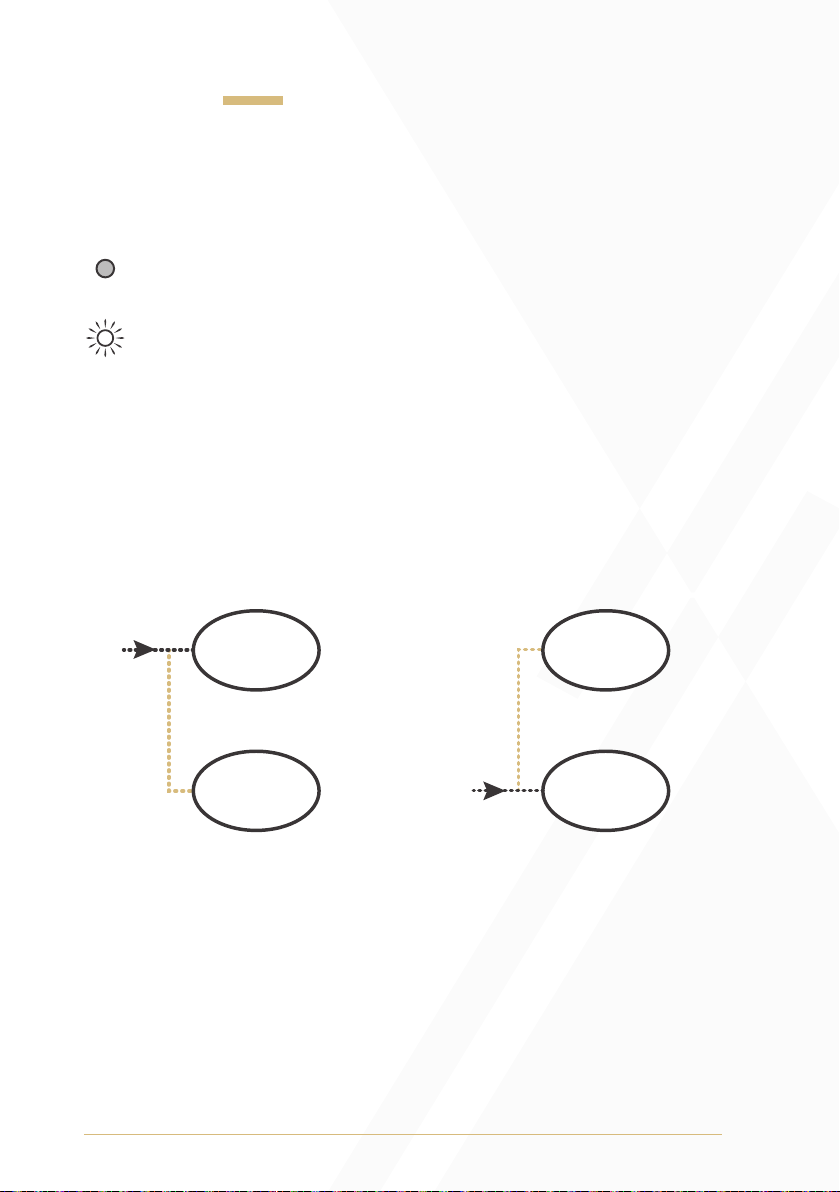
Link Button
The Link Button will bidirectionally normal 1V/Octave control voltage
signals from one oscillator to the other via either
1V/Oct Input.
If the Link Button is unilluminated, linking is diabled, and the
1V/Oct Input will control the corresponding oscillator only.
If the Link Button is illuminated white, linking is engaged. Sending
control voltage to the 1V/Oct Input of Oscillator A only will
control both Oscillators A and B. Similarly, sending control
voltage to the 1V/Oct Input of Oscillator B only will control both
Oscillators B and A.
• If a second 1V/Octave signal is patch in either of the above
configurations the Link routing normal is broken and the oscillators
will track independently.
13
 Loading...