

Instrument Transformer, Div of GE JCT-0C 600 V Data Sheet
GE
Grid Solutions
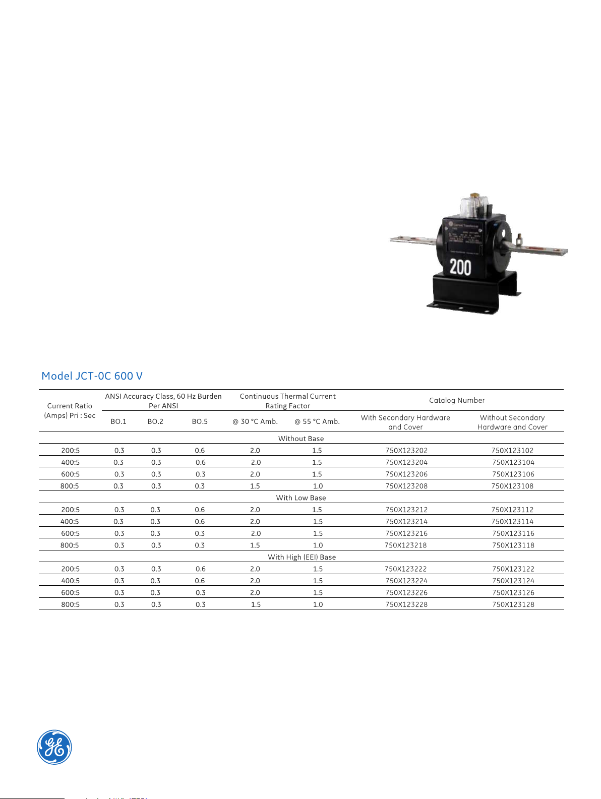
Model JCT-0C 600 V
Indoor Current Transformer
10 kV BIL With Integral Primary Bar
Application
Designed for indoor service; suitable for operating meters and instruments, on both
single-phase two-wire circuits and poly-phase circuits.
Weight
(Approximate in pounds)
Transformer, without base ...................7.0 lbs
Low base, add ..........................................0.25 lbs
High (EEI) base, add .................................1.0 lbs
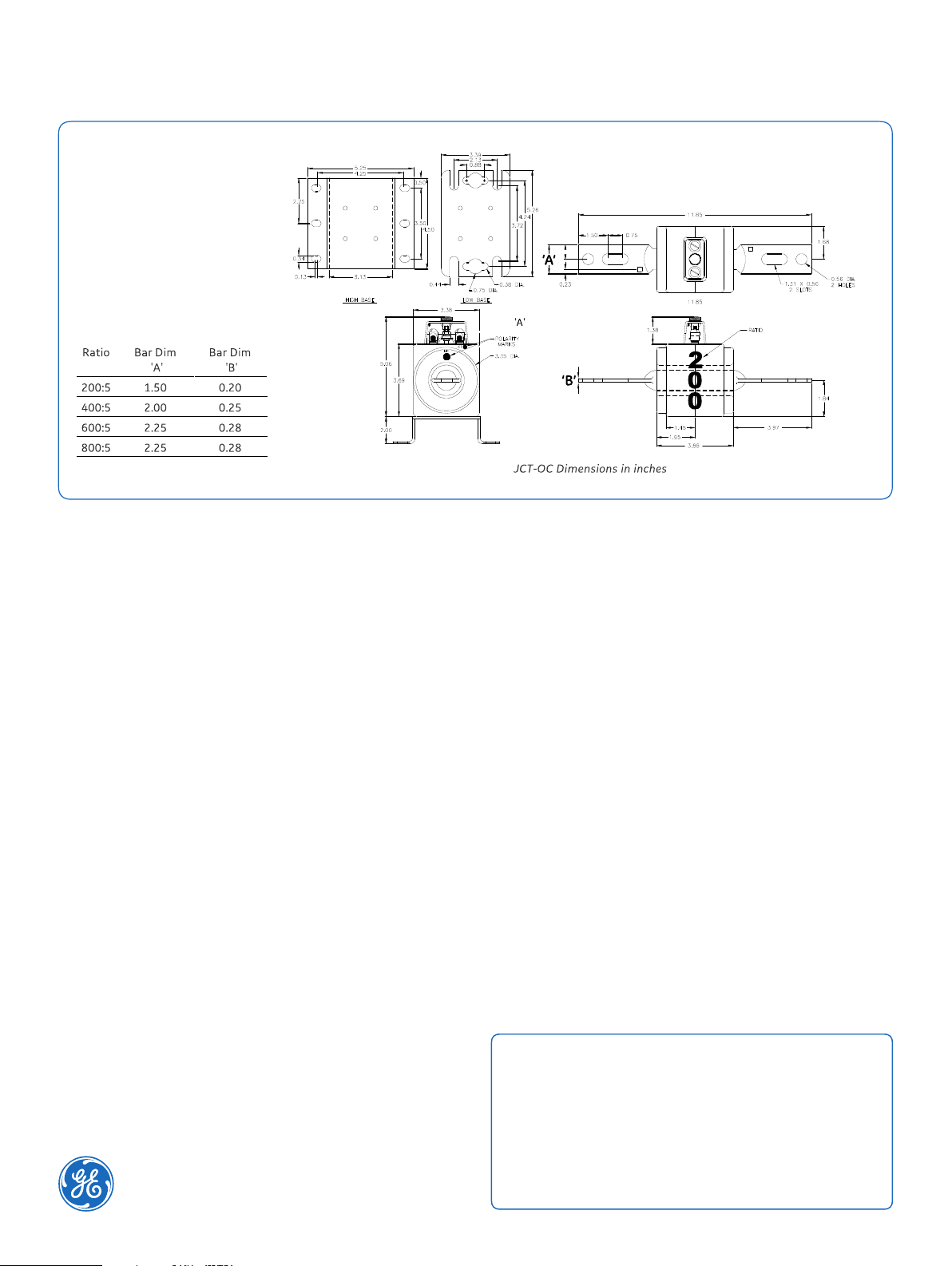
Reference Drawings
Outline 200:5 and 400:5............0121C33682
Outline 600:5 and 800:5............0121C44158
Insulation Level
0.6 kV; BIL 10 kV full wave.
Frequency
50-60 Hz
Model JCT-0C
identifying tag. The nominal current rating is marked on both sides
suspended from the bus-bar or cable. It has provision for attaching
The H1 polarity mark is molded into the case, above the win- dow
Dimensions in inches
Construction and Insulation
The core and coil are enclosed in a case molded with GE Valox
thermoplastic polyester resin. This tough material has excellent
electrical and mechanical properties over a wide temperature
range, has low water absorption and is resistant to oil and a
variety of chemicals.
Core and Coils
The core is made from high quality grain oriented silicon steel,
annealed under rigidly controlled factory conditions. The
secondary winding is made of heavy enameled copper wire. The
secondary windings are evenly distributed around the core for
maximum accuracy and resistance to stray fields from adjacent
conductors.
Terminals
Secondary terminals are tin plated brass, compression type with
a 0.275” diameter cross-hole for wiring and a 1/4-28 clamp
screw. A shorting device is provided and interlocked to the
terminal cover. The terminal cover is made of a clear plastic.
Provision is made for sealing the cover.
Polarity
at one end. The X1 polarity mark is also molded into the case
adjacent to the secondary terminal. Both H1 and X1 are marked
with white dots.
Primary Bars
Formed from copper tube, they are tin-plated. They are nonremovable and have a potential connector that can be attached
above or below the bar at either end. Primary bars conform to
ANSI C12.11.
Nameplates
The nameplate is laser engraved aluminum. It is attached to the
side of the unit and has provision for attaching the user’s
of the unit in large numerals.
Baseplate and Mounting
The transformer can be mounted in any position and may be
two optional bases. Low bases are made from stainless steel. The
high base increases the transformer height by 2 inches and meets
the dimensions specified in ANSI C12.11.
Maintenance
These transformers require no maintenance, other than
occasional cleaning, if installed where air contamination is severe.
ITI-Model-JCT-OC-Spec-EN-2018-01-Grid-AIS-1404. © Copyright 2018. General Electric Company
and Instrument Transformers LLC reserve the right to change specifications of described
products at any time without notice and without obligation to notify any person of such changes.
 Loading...