

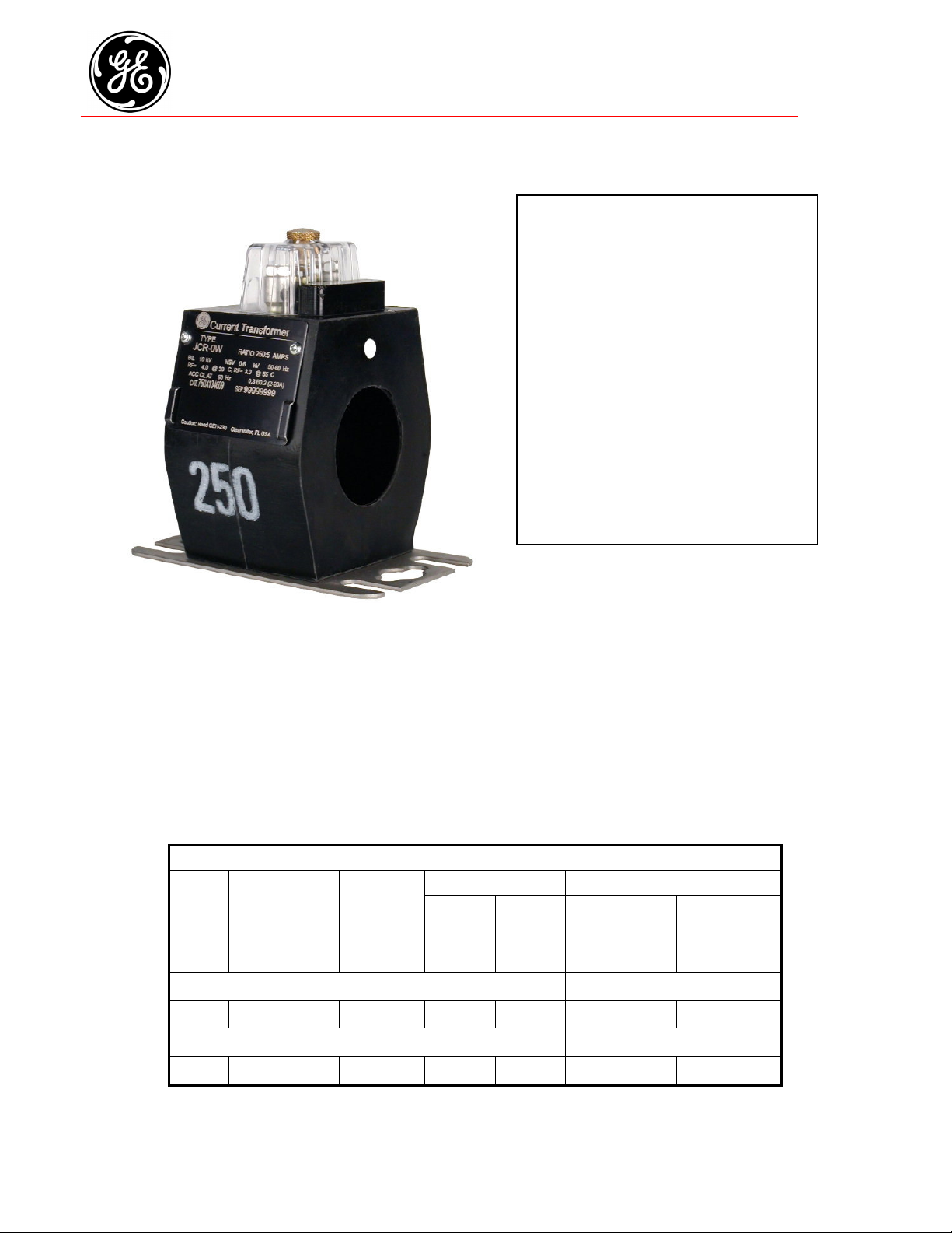
Encompass Current Sensor
Model JCR-0W 600V, 10kV BIL, 100-1000A
Window Diameter 2.00”
APPLICATION
Designed for both indoor and outdoor service.
Suitable for operating meters and instruments,
on both single-phase two-wire circuits and
polyphase circuits.
WEIGHT
(approximate)
Transformer,
Low Base ............4.0 lbs
High Base ............5.0 lbs
REFERENCE DRAWINGS
Outline ......0121C36111
INSULATION LEVEL
0.6kV; BIL 10kV full wave
FREQUENCY
50-60 Hz
JCR-0W DATA TABLE
Current
Ratio
(Amps)
Pri : Sec
ANSI Accuracy Class, 60
Hz
Burden Per ANSI 0.3 B0.2
Window
Size
(Inside Diameter)
Continuous Thermal Current
Rating Factor
Catalog Number
Without Base
@ 30oC Amb. @ 55oC Amb.
With Secondary
Hardware and Cover
Without Secondary
Hardware and Cover
250:5 100:2 to 1000:20 2.0” 4.0 3.0 750X134608 750X134611
With Low Base
250:5 100:2 to 1000:20 2.0” 4.0 3.0 750X134609 750X134612
With High Base
250:5 100:2 to 1000:20 2.0” 4.0 3.0 750X134610 750X134613
GEA-13375
250 250
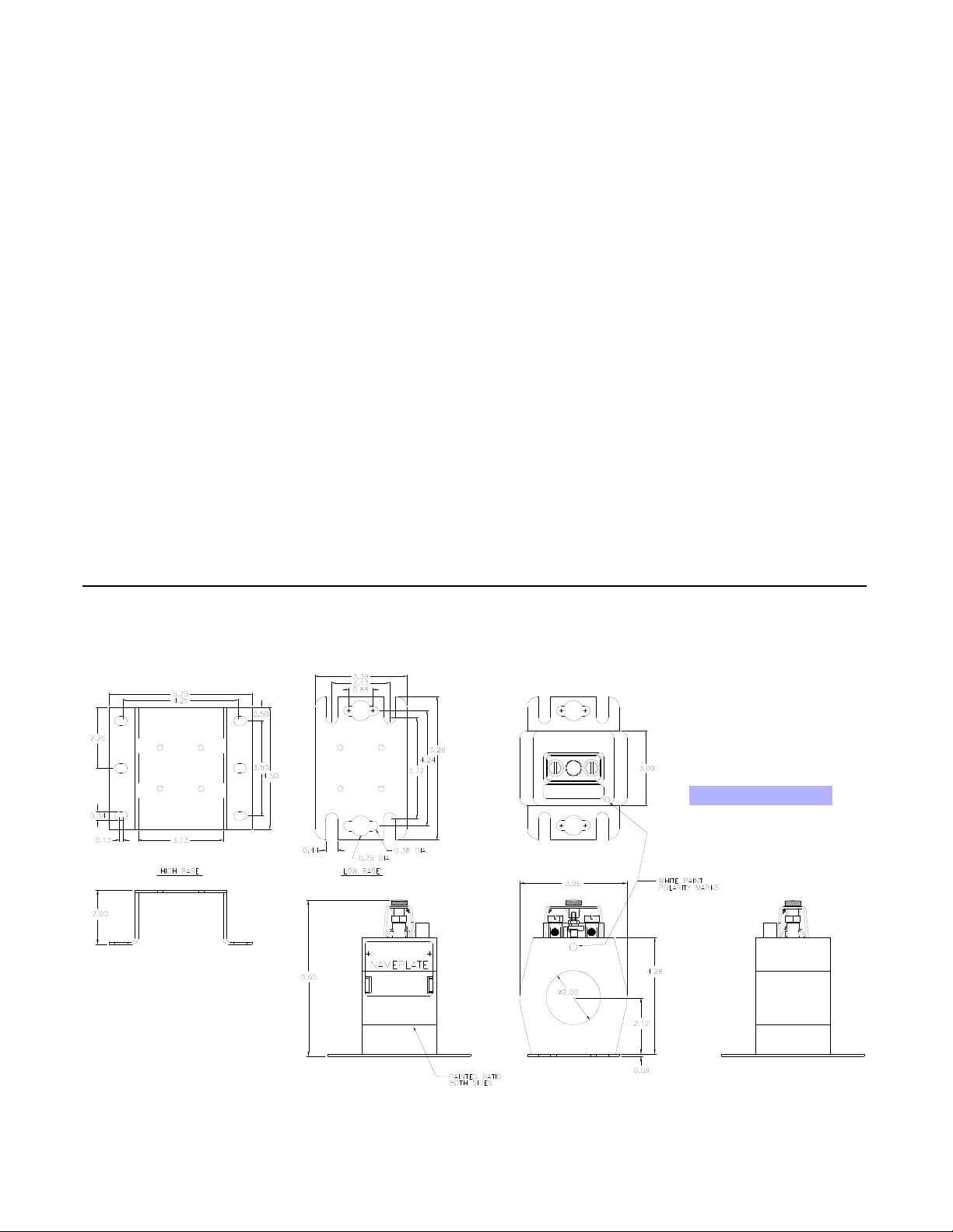
JCR-0W Dimensions
Construction and Insulation
The core and coil are encapsulated in a polyurethane resin.
This material has excellent electrical and mechanical
properties over a wide temperature range and is resistant to
oil and a variety of chemicals.
Core and Coils
The core is made from high quality grain oriented silicon
steel, annealed under rigidly controlled factory conditions.
The secondary winding is made of heavy enameled
copper wire. The secondary windings are evenly
distributed around the core for maximum accuracy and
resistance to stray fields from adjacent conductors.
Terminals
Secondary terminals are tin plated brass, compression type
with a 0.275” diameter cross-hole for wiring and a 1/4-28
clamp screw. A shorting device is provided and interlocked to
the terminal cover. The terminal cover is made of a clear
plastic. Provision is made for sealing the cover.
Polarity
The H1 polarity mark is molded into the transformer body,
above the window at one end. The X1 polarity mark is also
molded into the body adjacent to the secondary terminal.
Both are also identified with a white dot .
Primary Window
The window has ample size to accommodate cables of
current-carrying capacity equal to or greater than the
transformer’s thermal current rating.
Nameplates
The nameplate is laser engraved aluminum. It is attached to
the top of the unit and has provision for attaching the user’s
identifying tag. The nominal current rating is on both faces of
the unit in large numerals.
Baseplate and Mounting
The transformer can be mounted in any position and may be
suspended from the bus-bar or cable. It has provision for
attaching two optional bases. Bases are made from stainless
steel. The high base increases the transformer height by 2
inches and meets the dimensions specified in ANSI C12.11
Maintenance
These transformers require no maintenance, other than
occasional cleaning, if installed where air contamination is
severe.
Data subject to change without notice
 Loading...