

Page 1
GE
bushings
information,
transformer
Grid Solutions
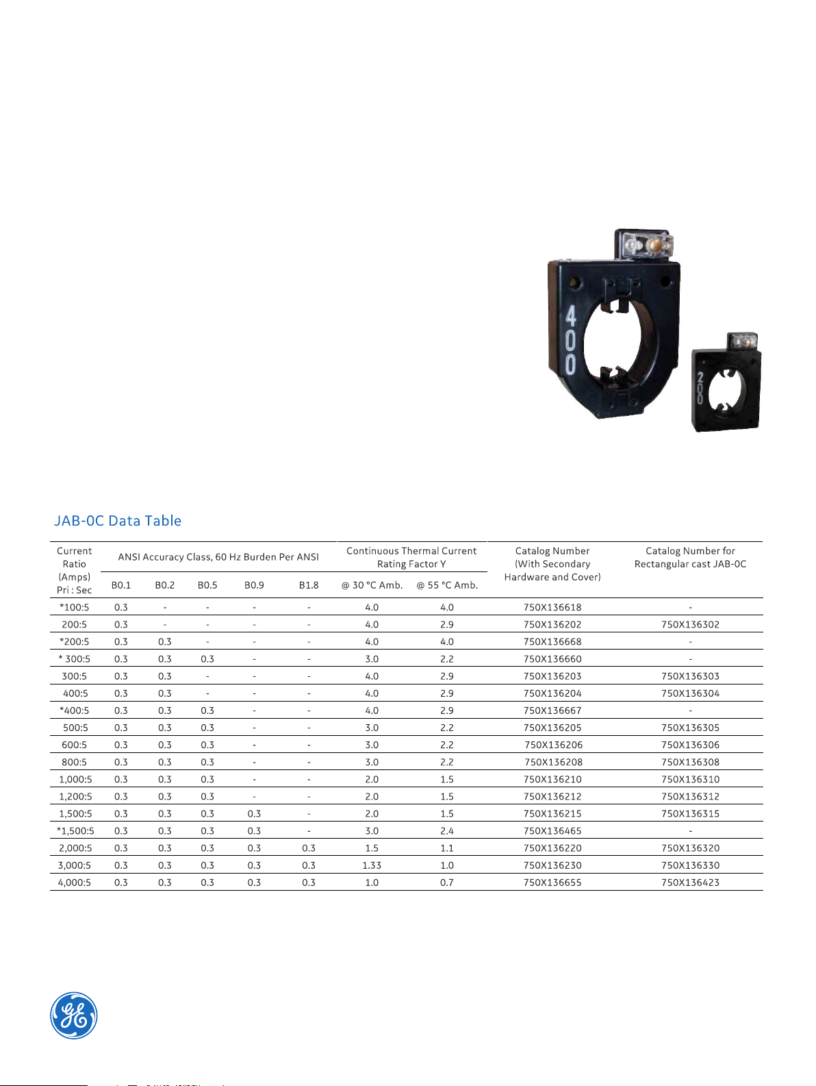
Model JAB-0C 600V
Indoor/Outdoor Current Transformer 10 kV BIL, 200-3,000 A
Window Size 4.50” X 3.50”
Application
Designed for indoor service; especially designed for installation over the secondary
of pad mounted transformers from 75 kVA. For mounting and application
including use at higher voltages, and matching the current rating to the pad
thermal capability, please refer to the Applications Information section of catalog GEP-9186.
Weight
Approximately ............8.25 lbs
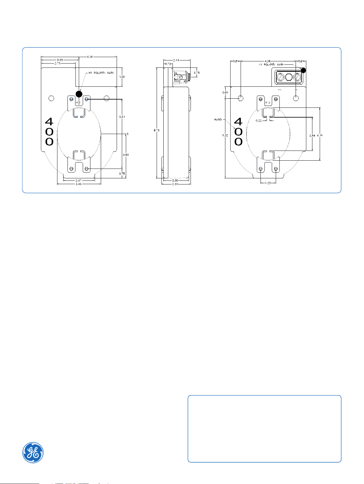
Reference Drawings
Outline 0121C33851
Outline (Rectangular) 0121C34472
Outline (2.88” cast) 0121C34503
Outline (2.00” cast) 0121C34986
Outline (2.50” cast) 0121C40892
Insulation Level
0.6 kV; BIL 10 kV full wave
Frequency
50-60 Hz
Notes:
A high temperature version is available for use in locations with unusually high ambient temperatures. Consult factory for base plate provisions.
* Grecian Urn Style available in cast version only. Consult factory for dimensions.
Page 2
water absorption and is resistant to oil and a variety of chemicals.
winding, leads and terminals to form a waterproof unit. Cast units
a 0.275” diameter cross-hole for wiring and a 1/4-28 clamp screw.
Model JAB-0C
the bushing and terminal blade of pad mount transformers, which
Construction and Insulation
The core and coil assembly is encapsulated in resin within a
molded case. The case is molded with GE Valox thermoplastic
polyester resin. This tough material has excellent electrical and
mechanical properties over a wide temperature range, has low
The polyurethane resin filling completely encapsulates the
are molded in polyurethane resin and have slightly larger
dimensions.
Core and Coils
The core is made from high quality grain oriented silicon steel,
annealed under rigidly controlled factory conditions. The
secondary winding is made of heavy enameled copper wire. The
secondary windings are evenly distributed around the core for
maximum accuracy and resistance to stray fields from adjacent
conductors.
Terminals
Secondary terminals are tin plated brass, compression type with
A shorting device is provided and interlocked to the terminal
cover. The terminal cover is made of a clear plastic. Provision is
made for sealing the cover.
Polarity
Primary and secondary marks H1, H2 and X1, X2 are molded into
the case. In addition, H1 and X1 are identified by white dots. Cast
units designate H1 with a white polarity mark only.
Primary Conductor
These transformers are primarily intended for installation over
then forms the primary conductor.
Nameplates
The nameplate is laser engraved aluminum. It is attached to the
top of the unit and has provision for attaching the user’s
identifying tag. The nominal current rating is on both faces of the
unit in large numerals.
Mounting
The transformer can be mounted in any position but is usually
installed on the pad mount tranformer terminal blade using the
Valox “grabbers”. The grabbers are removable and the
transformer also has two mounting holes allowing it to be
attached to a mounting bracket.
Maintenance
These transformers require no maintenance, other than
occasional cleaning, if installed where air contamination is
severe.
GEGridSolutions.com
Grid-AIS-L4-ITI_Model_JAB_0C-1375-2017_07-EN. © Copyright 2017. General Electric Company
and Instrument Transformers LLC reserve the right to change specifications of described
products at any time without notice and without obligation to notify any person of such changes.
Worldwide Contact Center
Web: www.GEGridSolutions.com/contact
Phone: +44 (0) 1785 250 070
USA and Canada: +1 (0) 800 547 8629
Europe, Middle East and Africa: +34 (0) 94 485 88 00
 Loading...