

Page 1
GE
Energy Connections
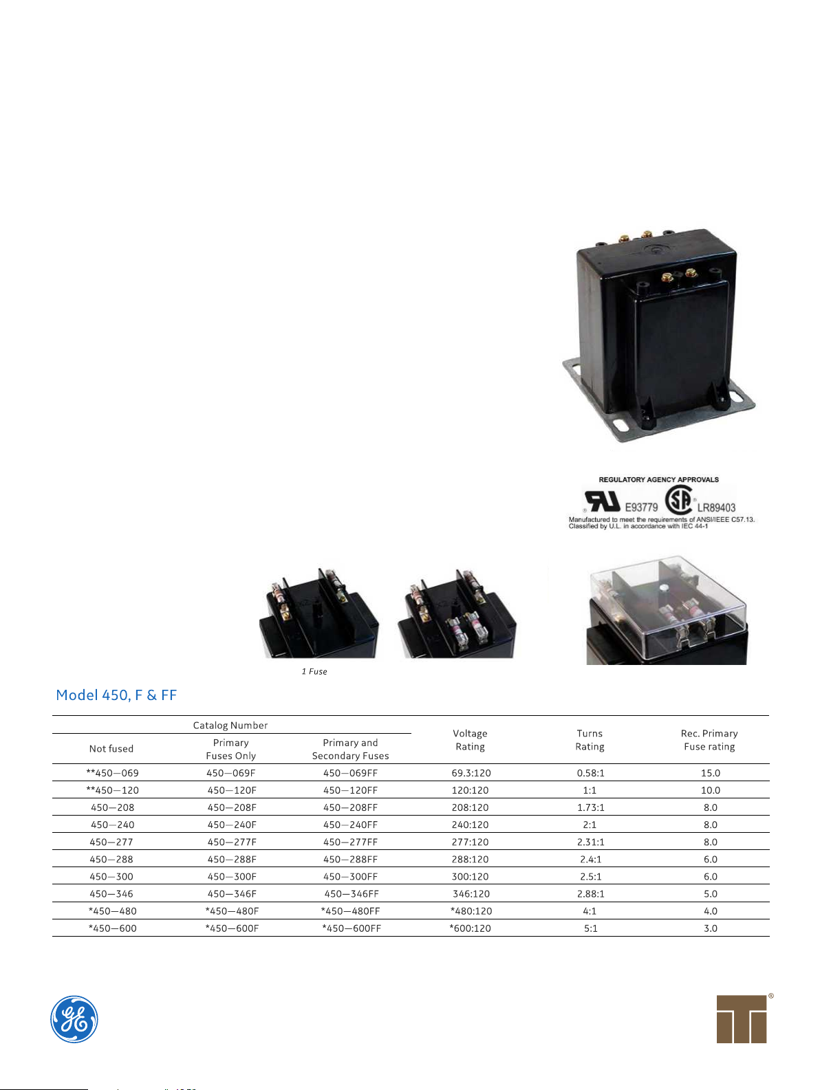
Models 450, F & FF
Voltage Transformers
Application
60 Hz.
Standard Secondary Voltage
120 Volts.
Insulation Level
600 Volt, 10 kV BIL full wave.
Accuracy Class:
0.3 W, X, M & Y, 1.2Z
Those marked ** are 0.3 W, 0.6 X, M & Y
Thermal Rating:
750 VA at 30 °C. amb., 500 VA at 55 °C.
amb.
The primary and secondary terminals
are No. 10-32 screws into 3/8” deep
brass inserts and fitted with one
lockwasher and flatwasher and are
contained in a sealable terminal cover.
Approximate weight 25 lbs.
No Fuse
2 Fuses
Clear Plastic Cover
Page 2
Models 450F & 450FF
The core and coil assembly is encased in a thermoplastic shell and filled with resin.
These transformers are designed for operation line-to-line. They may also be operated line-to-ground or line-to-neutral at reduced
voltage voltage, (58 % of rated volts).
It is desirable to use a 8.0 amp BBS type or equal fuse in the secondary to protect the transformer.
With two exceptions these transformer are ANSI C57.13 group 1. Those marked * are group 2.
Models designed specifically for 50Hz operation are available with reduced performance. Consult factory for details.
Fuse blocks containing type KTK-R (class CC) fuses can be fitted.
When primary fuses are requested, the rating will be as given in the table.
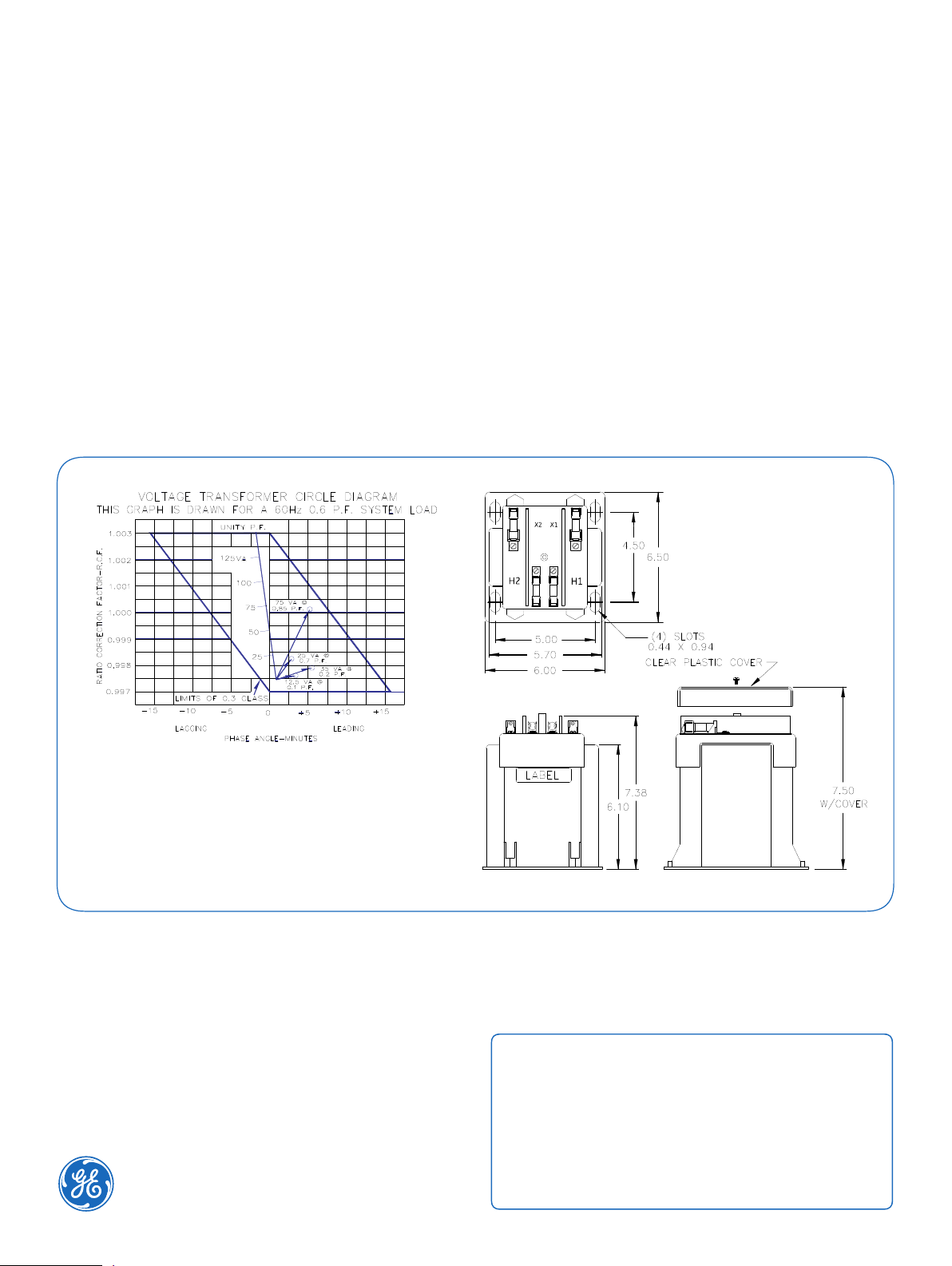
This page contains a circle diagram for the estimation of the errors for other than rated burdens. See page 27 in this section for a
description of its use.
When only one fuse is used, it must be connected into the line side (H1) terminal wiring. This will prevent the presence of voltage at the
H1 terminal
Grid-AIS-L4-ITI_Model_450-1413-2017_05-EN. General Electric Company and Instrument
Transformers LLC reserve the right to change specifications of described products at any time
without notice and without obligation to notify any person of such changes.
 Loading...