

Instrumentation Systems & Services L160 User Manual
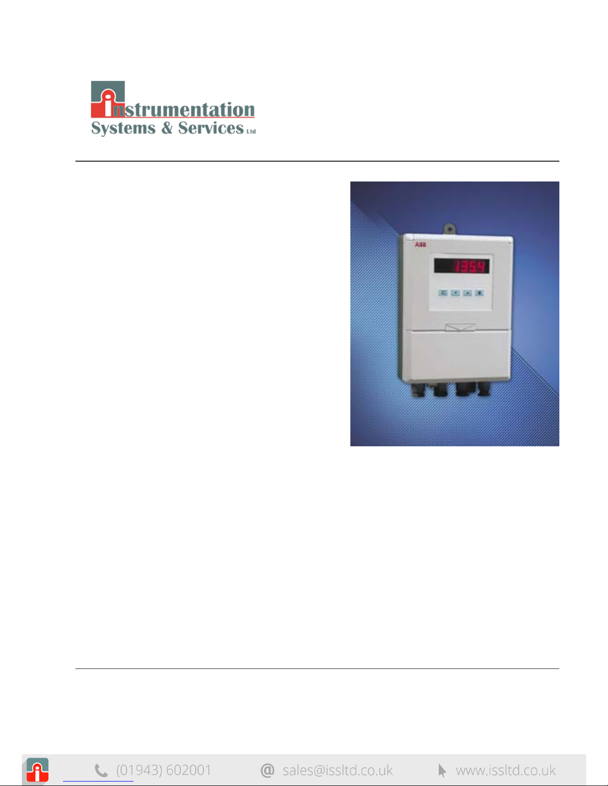
Wall-/Pipe-mount Level Indicator
L160
User Guide
IM/L160_6

Electrical Safety
This equipment complies with the requirements of CEI/IEC 61010-1:2001-2 'Safety
Requirements for Electrical Equipment for Measurement, Control and Laboratory Use'. If the
equipment is used in a manner NOT specified by the Company, the protection provided by
the equipment may be impaired.
Symbols
One or more of the following symbols may appear on the equipment labelling:
Health and Safety
To ensure that our products are safe and without risk to health, the following points
must be noted:
1. The relevant sections of these instructions must be read carefully before
proceeding.
2. Warning labels on containers and packages must be observed.
3. Installation, operation, maintenance and servicing must only be carried out by
suitably trained personnel and in accordance with the information given.
4. Normal safety precautions must be taken to avoid the possibility of an accident
occurring when operating in conditions of high pressure and/or temperature.
5. Chemicals must be stored away from heat, protected from temperature extremes
and powders kept dry. Normal safe handling procedures must be used.
6. When disposing of chemicals ensure that no two chemicals are mixed.
Safety advice concerning the use of the equipment described in this manual or any
relevant hazard data sheets (where applicable) may be obtained from the Company
address on the back cover, together with servicing and spares information.
Information in this manual is intended only to assist our customers in the efficient operation
of our equipment. Use of this manual for any other purpose is specifically prohibited and its
contents are not to be reproduced in full or part without prior approval of the Technical
Publications Department.
Warning – Refer to the manual
for instructions
Caution – Risk of electric shock
Protective earth (ground) terminal
Earth (ground) terminal
Direct current supply only
Alternating current supply only
Both direct and alternating
current supply
The equipment is protected
through double insulation
1
Displays and Controls
• Displays and function keys
• LED indication
• Error messages
Operator Mode (Level 1)
• Operator menus for:
– Standard level indicator
– Maximum/minimum/average level indicator
– Level indicator with volume indication
Set Up Mode (Level 2)
• Alarm trip points
• Alarm hysteresis levels
Configuration Mode (Levels 3 and 4)
• Accessing the configuration levels
• Level 3
– Hardware assignment and input type
– Alarm types and hysteresis
– Operator functions
– Digital input and serial communications
• Level 4
– Ranges and passwords
Installation
• Siting
• Mounting
• Electrical connections
8
GETTING STARTED
This manual is divided into five sections which contain all the information needed to
install, configure, commission and operate the DATUM L160. Each section is
identified clearly by a symbol as shown below.
Symbol Identification and Section Contents

2
CONTENTS
Note.
The fold-out page attached to the back cover of this manual
shows all frames in the programming levels. Space is
provided next to each frame to record programmed
settings/selections.
1 DISPLAYS AND FUNCTION KEYS ............................................................... 3
1.1 Introduction ............................................................................................ 3
1.2 Use of Function Keys ............................................................................. 4
1.3 LED Alarms and Indicators .....................................................................5
1.4 Error Messages ...................................................................................... 6
2 OPERATOR MODE ........................................................................................ 7
2.1 Introduction ............................................................................................ 7
2.2 Operating Page – Standard (Level 1) ...................................................... 8
2.3 Operating Page – Max./Min./Average Functions (Level 1) ....................... 9
2.4 Operating Page – Volume Function (Level 1) ........................................ 11
3 SET UP MODE ............................................................................................. 12
3.1 Introduction .......................................................................................... 12
3.2 Set Up Level (Level 2) .......................................................................... 13
4 CONFIGURATION MODE ........................................................................... 16
4.1 Introduction .......................................................................................... 16
4.2 Accessing the Configuration Mode ....................................................... 18
4.3 Basic Hardware and Indicator Functions (Level 3) ................................ 18
4.4 Ranges and Passwords (Level 4) .......................................................... 28
5 INSTALLATION ............................................................................................ 30
5.1 Siting the System ................................................................................. 31
5.2 Siting the Instrment .............................................................................. 32
5.3 Mounting the Instrument ......................................................................34
5.4 Electrical Connections .......................................................................... 36
5.5 Relays, Arc Suppression, Outputs and Input ........................................ 38
SPECIFICATION ................................................................................................... 39
3
tESt
A1
A2
A3
Alarm LEDs
(secret-till-lit)
Function Keys
Parameter advance
Raise
Lower
Multi-function key
A1
A2
A3
tESt
A1
A2
A3
2001.01
Displays shown during
the start up procedure
Displayed at startup
for 3 seconds
Software version and issue
eg. L160/2001, Issue 1
(displayed for 3 seconds)
Display
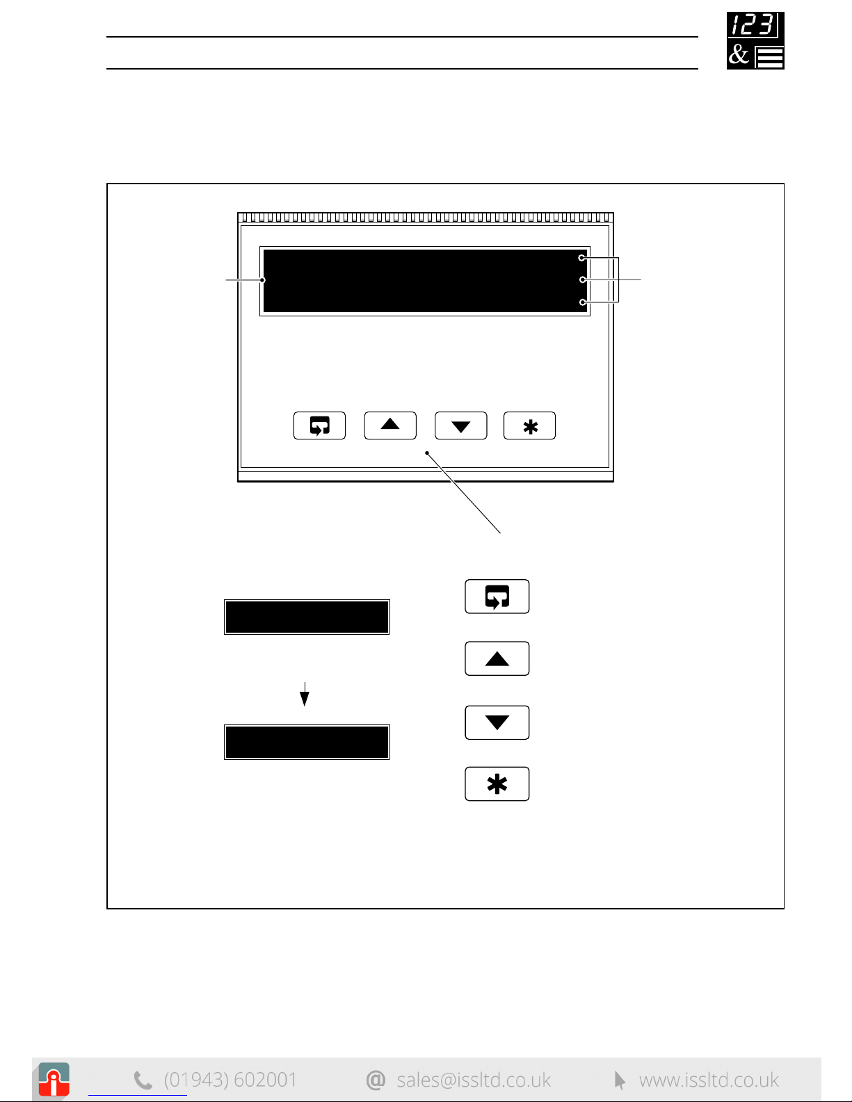
1 DISPLAYS AND FUNCTION KEYS
1.1 Introduction – Fig. 1.1
The DATUM L160 front panel display, function keys and LED indicators are shown in
Fig. 1.1.
Fig. 1.1 Front Panel Display, Function Keys and Indicators

4
A – Raise and Lower Keys
B – Parameter Advance Key
Frame 1
(top of level)
Frame 2
+
–
C – Multi-function Key
Use to change/set a parameter value…
Use to advance to the next
frame within a level…
or…
100.0 100.1
99.9
LEVEL1
100.1
CodE
0
Use to view a parameter setting or selection…or… …select individual
characters in a frame
123456
…move between levels
LEVEL1
LEVEL2
LEVELx
100.1
200.2
300.3
400.4
Press for
a few
seconds
or…
…select the top (LEVEL)
frame from within a level
Note. This key also stores any changes made in the previous frame
…1 DISPLAYS AND FUNCTION KEYS
1.2 Use of Function Keys – Fig. 1.2
Fig. 1.2 Use of Function Keys

5
Alarm 1
Alarm 2
Alarm 3
Alarm LEDs
A1
A2
A3
1 DISPLAYS AND FUNCTION KEYS…
1.3 LED Alarms and Indicators – Fig. 1.3
LED Status
All flashing Level indicator is in the configuration mode
– see Section 4.2
A1, A2 and A3 Flashes when Alarm is active (off when inactive)
Lit constantly when Alarm is an active, latched alarm
which has been acknowledged
Fig. 1.3 LED Alarms and Indicators

6
Error/Action
Start-up Screen
Displayed at system start-up.
Calibration error
Turn mains power off and on again
(if the error persists contact the
Service Organization).
Configuration error
The configuration and/or setup data
for the instrument is corrupted. Turn
mains power off and on again
(if the error persists, check
configuration/setup settings).
A to D Converter fault
The analog to digital converter is
not communicating correctly.
Sensor input out of range
Option board error
Communications to the option
board have failed.
Display
To Clear Display
Clears automatically
(after 3 secs.) to display
software version/issue
– see Fig. 1.1.
Press the key.
Press the key.
Turn mains power off and
on again. If the fault
persists, contact the
Service Organization.
Restore valid sensor input.
Check sensor output.
Contact the Service
Organization.
IP.FAIL
CAL.Err
CFG.Err
A.d. Err
OPt.Err
tESt
…1 DISPLAYS AND FUNCTION KEYS
1.4 Error Messages

7
2 OPERATOR MODE
2.1 Introduction
Operator Mode (Level 1) is the normal day-to-day mode of the DATUM L160.
Frames displayed in Level 1 are determined and limited by the indicator functions
which are selected during configuration of the instrument – see Section 4.
Note. Only the operating frames relevant to the configured functions are
displayed in Operator Mode.
The three indicator functions are:
• Standard Level Indicator – page 8
• Level Indicator with Max./Min./Average – page 9
• Level Indicator with Volume Indication – page 11

8
----
CodE
2145.3
UN-ACK
LEVEL1
•1
12.6
2145.3
G1.000
…2 OPERATOR MODE
2.2 Operating Page – Standard (Level 1)
Process Variable
Normally displayed in engineering
units.
To view the input value (in electrical
units) press the
key.
Global Alarm Acknowledge (latch alarms only)
UN-ACK
– alarm unacknowledged
ACK.
– alarm acknowledged
Specific Gravity
This is the value of specific gravity currently being
applied to the process variable (display only).
Security Code
Enter the password to access the Set Up Level
(Level 2) or the Configuration Level (Levels 3 and 4).
The default code is 0.
[0 to 9999]
Level 1
Note. To select this frame from anywhere in this level,
press and hold the
key for a few seconds.
•1 Displayed only if there is an active latch alarm.

9
rSt-n
2145.3
UN-ACK
A 140.5
H150.2
•1
2 OPERATOR MODE…
2.3 Operating Page – Max./Min./Average Functions (Level 1)
See Section 4.3.3 for details of Max./Min./Average functions.
Measured Level
To view the input value (in electrical units) press the
key.
Global Alarm Acknowledge (latch alarms only)
UN-ACK
– alarm unacknowledged
ACK.
– alarm acknowledged
Average Value
This is the mean average value of the process variable,
since the average was reset.
To reset the average value, select
rSt-Y
then press
the
key.
rSt-Y
– reset
rSt-n – do not reset
Continued on next page.
•1 The average value is displayed only if enabled in the configuration level
– see Section 4.3.3
The average value is reset automatically on power-up and can also be reset from
a digital input – see Section 4.3.4.
10
------
rSt-n
H150.2
rSt-n
L130.8
CodE
•1
•1
LEVEL1
G1.000
…2 OPERATOR MODE
…2.3 Operating Page – Max./Min./Average Functions (Level 1)
•1 The maximum and minimum values are reset automatically on power-up and can
also be reset from a digital input – see Section 4.3.4.
Maximum Value
This is the maximum value of the process variable since
the maximum was reset.
To reset the maximum value, select
rSt-Y
then press
the key.
rSt-Y
– reset
rSt-n
– do not reset
Minimum Value
This is the minimum value of the process variable
since the minimum was reset.
To reset the minimum value, select
rSt-Y
then press
the key.
rSt-Y
– reset
rSt-n
– do not reset
Specific Gravity
This is the value of specific gravity currently being
applied to the process variable (display only).
Security Code
Enter the correct code to access the Set Up Level
(Level 2) or the Configuration Level (levels 3 and 4).
[0 to 9999]
Level 1
Note. To select this frame from anywhere in this page,
press the
key for a few seconds.

11
----
CodE
2145.3
UN-ACK
LEVEL1
•1
12.6
2145.3
G1.000
V.23120
2 OPERATOR MODE…
2.4 Operating Page – Volume Function (Level 1)
Process Variable
Normally displayed in engineering
units.
To view the input value (in electrical
units) press the
key.
Global Alarm Acknowledge (latch alarms only)
UN-ACK
– alarm unacknowledged
ACK.
– alarm acknowledged
Specific Gravity
This is the value of specific gravity currently being
applied to the process variable (display only).
Volume
This is the current volume derived from the process
variable.
Security Code
Enter the correct code to access the Set Up Level
(Level 2) or the Configuration Level (Levels 3 and 4).
The default/factory-set code is 0.
[0 to 9999]
Level 1
Note. To select this frame from anywhere in this level,
press the
key for a few seconds.
•1 Displayed only if there is an active latch alarm.
12
8
LEVEL1
LEVEL2
A1xx
A1 HYSt
A2xx
A2 HYSt
A3xx
A3 HYSt
A xxxx
H xxxx
L xxxx
SPGrAV
Level 2 – Set Up
Alarm 1 Trip Point
Alarm 1 Hysteresis
Alarm 2 Trip Point
Alarm 2 Hysteresis
Alarm 3 Trip Point
Alarm 3 Hysteresis
Average Value
Maximum Value
Minimum Value
Specific Gravity
Offset Adjustment
Security Code 0 to 9999
(default/factory-set code = 0)
Level 1 –
Operating Level
Correct
Code
CodE x
0AdJ
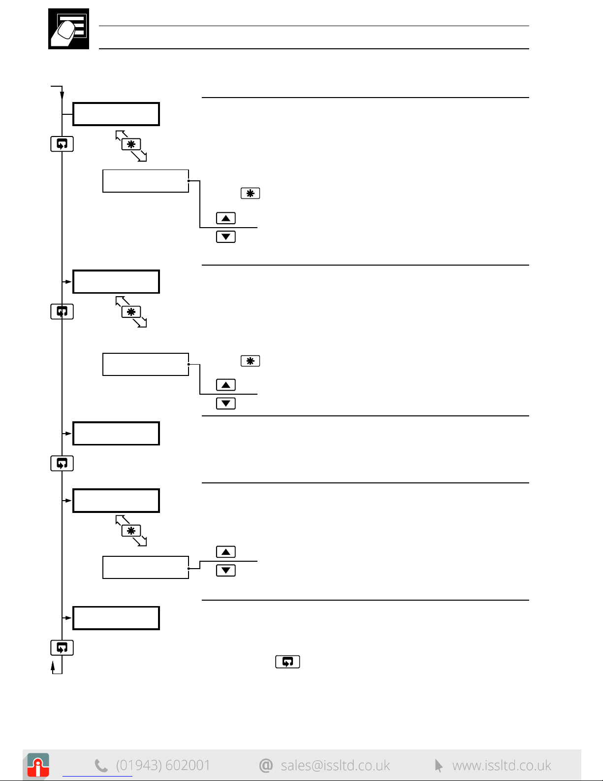
3 SET UP MODE
3.1 Introduction
To access the Set Up Level (Level 2) the correct code must be entered in the security
code frame (
CodE
) in Level 1 – see Sections 2.2 to 2.4.
Fig. 3.1 Accessing the Set Up Level (Level 2)
 Loading...