

Instrumentation Systems & Services DL169-IN-B, DL169-IN User Manual
1
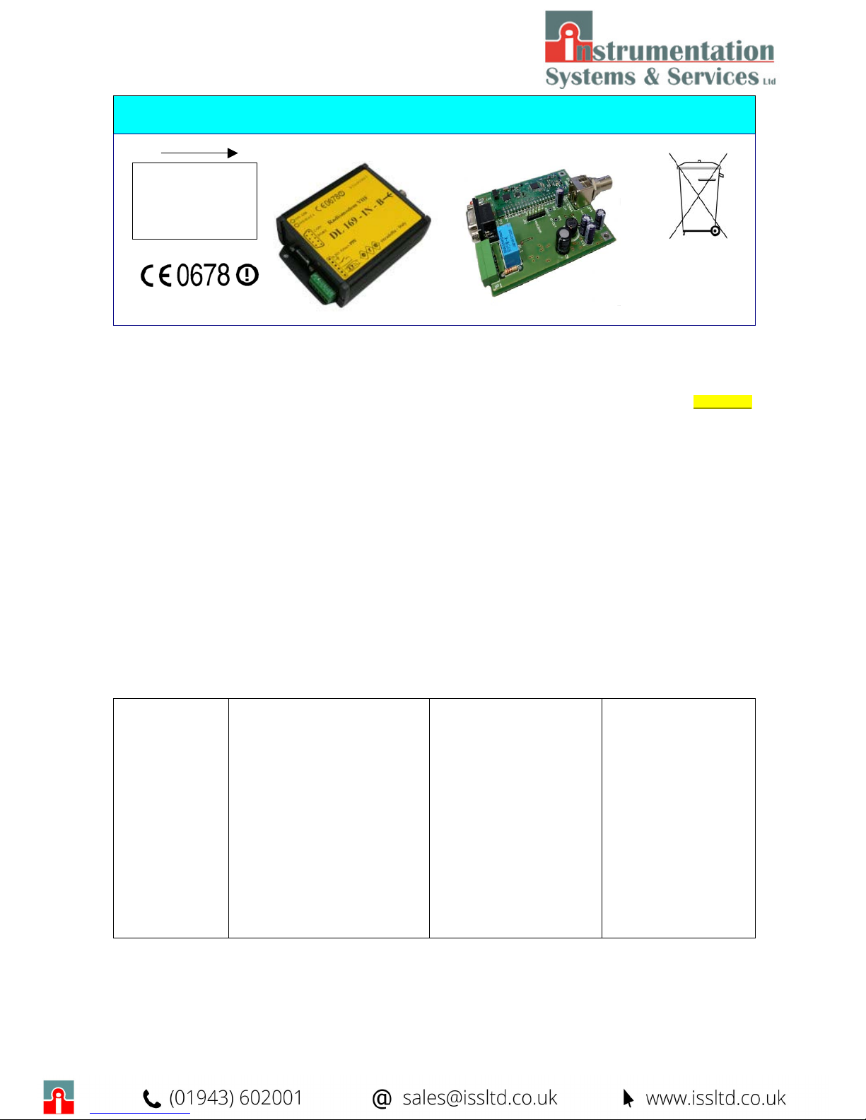
CE DL169-IN-B
RADIOMODEM VHF
DL169-IN CE
General Informations:
DL169-IN-B is a VHF simplex/half-duplex high quality radiomodem with an output power of 200 mW
ERP
with a dedicated λ/4
antenna mod. ANT169L, or a vertical dipole mod. ANT169DV, operating on six 12,5 kHz channels or three 25 kHz channels in the
169.400 – 169.475 MHz band in according to the European Decision 2005/928/CE. These products are characterised by
FREE USE.
The radiomodem is enclosed in an extruded aluminium box containing the RS232/RS485 interface and supply unit card RMO148.
DL169-IN defines the same device without the box while DL169 is the basic unit without the RS232/485 interface and supply. In
this case a direct TTL interfacing is required and it represents the more favourable solution for a direct microcontroller connection.
The following models DL169-IN-B-Y3, DL169-IN-Y3 and DL169-Y3 are the same devices equipped with a three elements Yagi
antenna.
All the Radiomodems are fully transparent to the user and configurable from the PC by dedicated software for the desired functions.
Features:
- Store & Forward mode with 448 Bytes maximum Buffer size
- ON/OFF switching controlled via DTR criteria
- Low power consumption in both RX and TX mode with selectable Power Saving mode from configuration software
- Broadcasting Mode or Address management through configuration software or directly from DTE
- Digital Repeater (digipeater) Mode to permit communications between two or more hidden stations
- Remote programming of the devices and channel selection from DTE
- More sophisticated charachteristic as : ACK and repetition of the not received messages, address reversing for the answer,
ECHO, NAK to DTE at the end of repetitions, address to DTE and so on.
These devices, assembled with SMT components in the industrial temperature range, is particularly suitable for Low-Cost radio
networks in which the battery or solar cells supply require a low power consumption together an high quality product
.
General
Operating band
Channel number
Canalisation
Modulation
Radio data rate (Tx / Rx)
Frequency stability
Supply voltage
Rx consumption
Tx consumption
Consumption DTR OFF
Antenna
Dimension H x W x D
Operative temperature
Reference Directives
Out switch aux
Digital input
169.400 - 169.475 MHz
3 @ CH 25 kHz , 6 @ CH 12.5 kHz –
under European Decision 2005/928/CE
12.5 kHz or 25 kHz
9K00F1D or 18K0F1D
4,800 bps @ 12.5 kHz – 9,600 bps @ 25 kHz
±500 Hz
8 → 36 Vdc with limited source power
~ 30 mA @ 12 Vdc – RS232/485 Relay OFF
~ 300 mA
< 1 mA
λ/4 - λ//2 o 3 elements Yagi
100 x 90 x 40 mm ( 3.94 x 3.54 x 1.58 inches)
–30 → +70 °C ( -22 → 158 °F)
EN 300 220-1 v2.3.1 , EN 300 220-2 v2.3.1
N.O. 28 Vac @ 0,5 A o 60 Vdc @ 1 A
5 → 24 Vdc or 3.50 → 20 Vac. Zinp: 2.2 kΩ
Transmitter
Output Power
Frequency deviation
Output power stability
Adjacent channel power
Ch. adjacent transitory power
Receiver – Class 2 - LBT and Agility
Sensitivity @ BER< 10
-2
Aadjacent channel attenuation
Blocking
Interface
Data rate (Interface)
Data format (standard)
Operative modality
0.20 W
ERP
(DL169-IN-B)
0.5 W
ERP
(DL169-IN-B-Y3)
± 1.8 kHz @ 12,5 kHz ± 3.6 kHz @ 25 kHz
±1.5 dB
compliant EN 300 220-1
compliant EN 300 220-1
<-110 dBm @ 12.5 kHz
<-107 dBm @ 25 kHz
compliant EN 300 220-1
compliant EN 300 220-1
RS 232 e RS 485
1,200 to 38,400 bps
Asynchronous 8,N,1- 8,E,1-8,O,1
Simplex or half-duplex
RS 232-RS 485
INTERFACE +
1 INPUT , 1 OUTP.
GALVANICALLY
ISOLATED
All stated specifications are subjected to
change without notice
or obligation.
2
DL169-IN-B – The circuit
Radiomodems DL169-IN-B and its open version DL169-IN are built by the interface and supply card
RMO148 and the radiomodem module DL169.
The RMO148 card realises the following functions:
- Power supply conditioning. A step-down switching regulator give a stabilised voltage of 5 Vdc from an
input voltage between 8 to 36 Vdc. It feeds directly the RS232/RS485 interfaces and, through a drop dio de, the RF power amplifier. A 3.3 Vdc linear regulator is used for the DL 169 m
odule.
- Optoisolated input for digital input requires a DC input from 5 to 24 V or AC input from 3.5 to 20 V.
The input impedance is of 2.2 kΩ, resistive.
- Relay Output, normally Open, can manage a 28Vac 0.5 A current or 60Vdc 1 A current
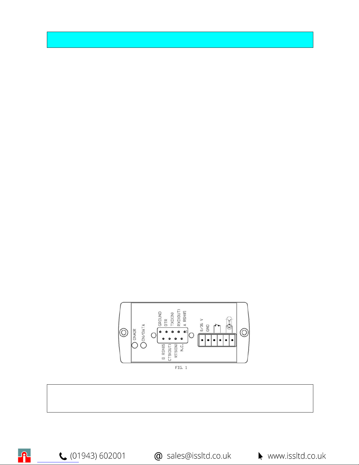
- RS232 and RS485 interfaces both on the D-shell female connector. The interface selection is achieved
by configuration software trough electronic switch. As shown in the following Fig. 1 the RS 232
interfaces utilises the connector pins from 2 to 8 while the RS 485 utilises the pins Nos. 1 and 9.
- Radiomodem status with a bi-colour LED normally green. The data flow into or out the unit causes the
color change (from green to orange) of this LED. During the configuration process this Led is orange.
A second Red Led is turned on during the transmission.
- Antenna connection with a BNC female connector.
DL169 MODULE – The DL169 Radiomodem used in this application is programmed with a specific
firm
ware version using the RTXEN, CONFIG, CH0, CH1, CH2 criteria to manage respectively:
- Optoisolated Input
- Output DATA Led
- Relay output
- RS 232 enable
- RS 485 enable
The remaining criteria retain the original features. Detailed information on the module are available on the
DL169 ma
nual.
CE DL169-IN-B
RADIOMODEM VHF
DL169-IN CE
The equipment is FREE USE for telemetry & command, AMR, tracing and tracking of goods
Regulatory standards: EN 300 220-1 v2.3.1 , EN 300 220-2 v2.3.1 , EN 60950-1: 2001+All A11 2004 ,
EN 301 489-1/3
ERE Stradella Italy DL169-IN-B
3
Products and ancillary :
The equipment is FREE USE for telemetry & command, AMR, tracing and tracking of goods
Regulatory standards: EN 300 220-1 v2.3.1 , EN 300 220-2 v2.3.1 , EN 60950-1: 2001+All A11 2004 ,
EN 301 489-1/3
ANTENNA: SELECTION AND CONNECTION
Indoor use:
1) Use the λ / 4 models, ANT119/BNC (shortened) or ANT169L/BNC (full length) with BNC male connector to be inserted
directly in the antenna output of the Radiomodem. If the Radiomodem is supported on a plan, provide a right angle adapter
BNC M / F to keep the antenna vertical.
2) The Radiomodem can be inserted into a plastic or metal box (preferably). Provide a 13 mm hole to fix the panel TNC female
connector of an extension cable BNC / M-TNC / F and plug the BNC male on the Radiomodem antenna connector.
3) Improved efficiency may be obtained using the vertical dipole antenna ANT169DV. This is supplied with 5 meters of low loss
coaxial cable and don’t requires the ground plane so may be installed in the most favourable mode.
Outdoor use:
For external applications the Radiomodem need to be inserted into suitable containers for IP67 protection or better. These solutions
can be used:
1)
Close the Radiomodem in a plastic or, better, metal container. Provide a 13 mm hole to fix the panel TNC female connector of
an extension cable BNC / M-TNC / F and plug the BNC male on the Radiomodem antenna connector. Take care to assure an
efficient electric contact between the ground of the panel TNC female connector and the metallic box. If the container is of an
insulating material, the absence of the ground plane for the λ/4 antennas decreases the radiation efficiency. To minimise this
decreasing in efficiency a metal strip or a wide wire placed in the internal side of the box and electrically connected to the TNC
ground, simulates the ground plane and allows the utilisation of the λ/4 antennas ANT119/TNC (shortened) or ANT169L/TNC
(full length). For maximum efficiency in this case the vertical dipole ANT169DV is recommended.
2) The Radiomodem will be contained in a plastic or metal box with IP67 protection or better. Provide the required holes on the
bottom side of the box to fix the wall-pass cable for both antenna and supply/serial line cables. It’s possible to use the vertical
dipole antenna ANT 169DV or, in the Y3 suffix versions, the 3 elements Yagi antenna WY 155 3N to perform both the
directivity feature and a reception gain of 3 – 4 dB, keeping the maximum transmitted ERP power within 500 mW.
NOTE ON POWER SUPPLY
The Radiomodem DL169 or DL169-IN-B should be fed with a power limited voltage source between 8 and 36 Vdc and is not required a stabilisation due to the presence of an internal efficient stabiliser. The power supply is protected against polarity reversing
and is protected by a 750 mA internal SMT fuse. The current drawn depends on the power supply voltage and reaches it’s maximum
value during the transmission with the minimum supply voltage. A value of 450 mA may be used to choose an adequate supply unit.
a) DL169-IN………………
b) DL69-IN-B…………….
c) DL169-IN-Y3………….
d) RMO169-N-B-Y3……...
g) DP03……………………
Radiomodem with RS232 and RS485 interfaces without box (open card version):
available with antenna lambda/4 ANT119, ANT169L or vertical dipole ANT169DV
Radiomodem with RS232 and RS485 interfaces included in an extruded Aluminium box:
available with antenna lambda/4 ANT119, ANT169L or vertical dipole ANT169DV
Radiomodem with RS232 and RS485 interfaces without box (open card version):
available with 3 elements Yagi antenna WY 155 3N or ANT294
Radiomodem with RS232 and RS485 interfaces included in an extruded Aluminium box:
available with 3 elements Yagi antenna WY 155 3N or ANT294
Connection for guide DIN in extruded Aluminium

ERE Stradella Italy DL169-IN-B
4
Starting use:
The DL169 device is delivered with the following default configuration:
♦ 169.40625 channel radio in broadcasting mode, transparent to the user.
♦ 9,600 bps UART Data Rate, 8,N,1 format, No Flow Control and 448 Bytes Buffer size
♦ 4,800 bps Radio Data Rate with 12,5 kHz canalisation
♦ RF Output Power of 200 mW
The device, if is not required a specific configuration, may be immediately utilised connecting it to a RS 232 or RS 485 serial
interface of dedicated DTE ( PC, RTU, PLC or other ) .
The device configuration may be done by the Configuration Software DL148SW-IN, available for free download from ou
r
website, and the internal Help shows all the necessary information on the software utilisation and configuration parameters.
Detailed information about the device protocol are available in the DL148Pro file , available, as the previous, from our website.
Special functions:
LBT – Listen Before Talk – If enabled, before the transmission of a packet, the radiomodem checks the status of the operating
channel by a period of 5 milliseconds and ,only if the channel is free for all this period, the transmission start. The free/busy
threshold is set to –103 dBm for 12,5 kHz canalisation and to –100 dBm for 25 kHz canalisation in according to the Europea
n
directives. If during the checking period the channel status changes from free to busy condition, the radiomodem reset the
procedure and it restart when the channel come back to free condition. The incoming data to transmit is stored in the internal
buffer until the radiomodem can transmit it, so the Flow Control option must be enabled to stop the next incoming data from
DTE.
AFA – Adaptive Frequency Agility – In the configuration process is possible to select 1, 2 or 3 channels as above specified.
When more than 1 channel is selected the AFA mode automatically starts, so the radiomodem scans the selected channel and
transmit on the less interfered one. If also LBT is enabled, the LBT thresholds are used to define the free channel and the uni
t
transmit on this one.
Using the LBT and AFA the Duty Cycle limits of the European directives can be exceeded.
Of course, if these functions are selected, all the units in the communication network must be configured with these functions
to allow the communication process because the improvement of the reliability of the communication is obtained lengthening the
preamble time. If, normally, the preamble times are of 8.35 and 5.83 milliseconds respectively for 12.5 or 25 kHz canalisation,
they become of 25 or 20.75 milliseconds for two channels and of 36.74 or 30.71 milliseconds for three channels.
DUTY CYCLE: If it is not used the LBT+AFA function the Duty cycle mediated on the hour must be respected (10% metering
& commands, 1% tracking and tracing).
PWSAVING -
The Power Saving function allows a considerable energy saving in all situation where the device is feed by
a
b
attery or solar cells and, of course, this saving is obtained lengthening the transmitting periods. This may have the appearance o
f
a nonsense, but the maximum amount of energy is spent in the receiving status because the transmitting mode is normally shorter
than the receiving one. In the Power Saving mode the ON time of the unit is internally set to 13 or 10 milliseconds, respectively
for 12.5 or 25 kHz of canalisation, while the OFF time can be set in configuration in 10 milliseconds step. The preamble time
length is increased by the selected PwSavOFF time and, of course, this time must be the same in all units of the communication network. An incoming preamble from radio and/or an incoming data on the serial port exits the unit from the Power
Saving condition and it stays in the normal operative condition until the selected PWSava time is expired. During the PWSava
time the radiomodem utilises a normal length preamble so the answer can be transmitted in the allowable shortest time.
The PWSava time can be selected in the 100 milliseconds to 25,400 millisecond range. The value PWSava = 255 keeps the
unit always operating but the generated preambles have a length defined by the selected PwSavOFF time. This feature may be
useful when the Master unit and the digipeaters, if presents, are supplied by the Main to allow the decoding of both short or long
preambles. The PWSava time can modify the total amount of supplied energy, so its correct choice is fundamental for the bette
r
results. For detailed information please refer to the Configuration Software Help an the protocol description.
Att.!! the maximum time of transmission in order to respect the norm EN 300 220-1 v2.1.1 is ≤ 1 sec.
 Loading...